
Alternator Wire replacement problems.
 Jul 6, 2013 | 06:06 PM
#1
Thread Starter
Registered User
Joined: May 2013
Posts: 419
Likes: 0
From: SC Backwoods
Alternator Wire replacement problems.
Hey Fellas,
I am posting this here so as not to clutter up my build thread, hope thats okay with the mods. If not feel free to remove it.
Ok the problem.
Since i bought my truck 94 ext cab 4x4 22re a few months ago i have had the alt charge light flashing at me intermittently, generally when i flick the high beams on. So after upgrading the other components of the big three i decided to take a look at my alt and see if i could fix the problem. What i found:
So i decided that was probably my problem.
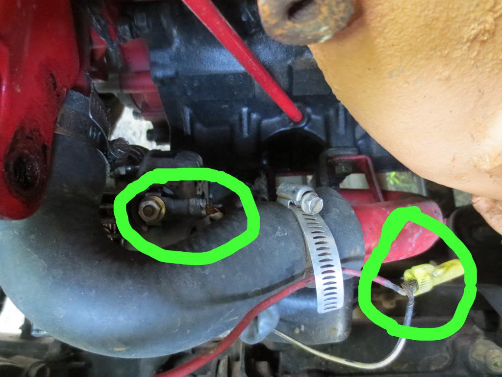
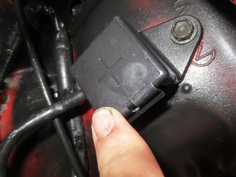
Out came the air box, miles of old loom and brittle tape, and then the alt charge wire. I was slightly surprised that it did not go all the way to the fuse box, it terminated in this box behind the air box(note the alt wire had already been removed at the time this pic was taken):
So after feeling confused for a sec i realized this was really kinda good as it meant i only had to replace a small section of wire rather than the whole thing. When i pulled this section of wire i found that the alt end had this unique ring terminal attached:
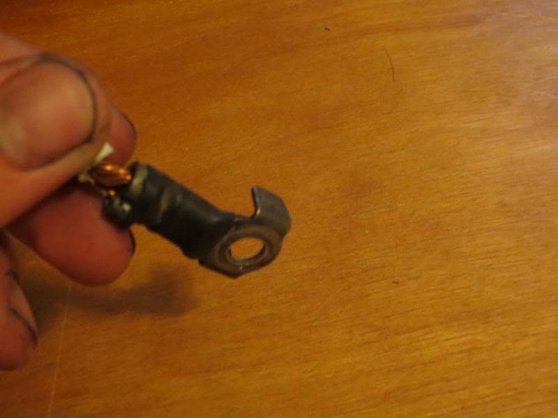
I have never seen one of these before and was having trouble finding a replacement at the hardware store so after a good look at the stud it ties down on i figured the ears probably did nothing more than increase the surface contact and replaced it with a standard ring terminal.
That done i put it all back together and cranked her up. And was greeted almost immediately by that friendly flashing battery light. The alternator is not charging since my wire replacement.
I am assuming that the cause is the bunny eared connector i dispensed with. Before coming to this conclusion i pulled the air box back off and checked my connections, but they were all solid.
Is that the case? Or should i be looking elsewhere for the issue, because this alternator did work(at least to a greater extent than it does now) before the replacement.
Any and all ideas welcome, this is my dd and i need it back up and running asap.
Thanks,
Speed
I am posting this here so as not to clutter up my build thread, hope thats okay with the mods. If not feel free to remove it.
Ok the problem.
Since i bought my truck 94 ext cab 4x4 22re a few months ago i have had the alt charge light flashing at me intermittently, generally when i flick the high beams on. So after upgrading the other components of the big three i decided to take a look at my alt and see if i could fix the problem. What i found:

So i decided that was probably my problem.
Out came the air box, miles of old loom and brittle tape, and then the alt charge wire. I was slightly surprised that it did not go all the way to the fuse box, it terminated in this box behind the air box(note the alt wire had already been removed at the time this pic was taken):

So after feeling confused for a sec i realized this was really kinda good as it meant i only had to replace a small section of wire rather than the whole thing. When i pulled this section of wire i found that the alt end had this unique ring terminal attached:

I have never seen one of these before and was having trouble finding a replacement at the hardware store so after a good look at the stud it ties down on i figured the ears probably did nothing more than increase the surface contact and replaced it with a standard ring terminal.
That done i put it all back together and cranked her up. And was greeted almost immediately by that friendly flashing battery light. The alternator is not charging since my wire replacement.
I am assuming that the cause is the bunny eared connector i dispensed with. Before coming to this conclusion i pulled the air box back off and checked my connections, but they were all solid.
Is that the case? Or should i be looking elsewhere for the issue, because this alternator did work(at least to a greater extent than it does now) before the replacement.
Any and all ideas welcome, this is my dd and i need it back up and running asap.
Thanks,
Speed
Jul 6, 2013 | 06:51 PM
#2

Registered User
Joined: Jan 2013
Posts: 57
Likes: 0
The ears keep the connector stable.
Looks like someone re-wired the alternator.
Search the forums for alternator upgrades/ rewiring.
https://www.yotatech.com/forums/f116...toyota-264252/
http://www.pirate4x4.com/tech/billavista/Wiring/Part2/
Basically you should run a new wire from the Alternator post [I used 10gauge when I upgrade to a GM100amp Alt] through a fuse to the battery positive, I think I ran a new ground: Alternator - Engine block also.
Check your engine block ground to battery is good.
You should be able to find that connector at an Auto parts shop.
Highly recommend the GM Alt upgrade, I bought a bracket [http://www.lowrangeoffroad.com/index...-bracket.html]
but did not the buy the plug and play connectors.
Next time I do this I will buy the plug and play connectors but see if I can avoid removing the Toyota bracket [real pita to get to the bolts].
Good Luck
Last edited by milkybar; Jul 6, 2013 at 06:53 PM.
Jul 7, 2013 | 01:40 AM
#4
Registered User
iTrader: (1)
Joined: Apr 2009
Posts: 13,381
Likes: 100
From: I live in New Tripoli Pa out in the woods
 You do have a Meter to check what is really going on??
How did you make your connections ??
Crimp?? Solder??
The flashing light means an intermittent issue One wonders just what else might be cobbled together.
Unless this is a low brake fluid issue as the 2 lights are tied together.
Jul 7, 2013 | 06:21 AM
#5
Registered User


Joined: Nov 2012
Posts: 1,192
Likes: 182
From: Tucson
Those ears are there to keep the terminal in position, from rotating when you tighten it.
I have replaced many with regular terminals and had no problem. If your wire and crimp are good it is not your problem.
Is the plug in connector good? What about the main fuse? Doesn't your main alt wire go to the fuse then back to the battery?
If all your wiring checks out and your belt is tight, it's time to test your alt. Should be putting out 14.5 volts or so.
Jul 7, 2013 | 07:52 AM
#6
Thread Starter
Registered User
Joined: May 2013
Posts: 419
Likes: 0
From: SC Backwoods
The ears keep the connector stable.
Looks like someone re-wired the alternator.
Search the forums for alternator upgrades/ rewiring.
https://www.yotatech.com/forums/f116...toyota-264252/
http://www.pirate4x4.com/tech/billavista/Wiring/Part2/
Basically you should run a new wire from the Alternator post [I used 10gauge when I upgrade to a GM100amp Alt] through a fuse to the battery positive, I think I ran a new ground: Alternator - Engine block also.
Check your engine block ground to battery is good. I may end up doing this, but i was hoping to get away with just fixing(replacing the broken wire) until i have the cash and the need to upgrade my alt. And at that point upgrade all the wiring as needed, i hate to do work twice.
You should be able to find that connector at an Auto parts shop. Thats what i thought Advance had no clue and oriellys said they could maybe order it in, both recommended home depot, who responded and i quote "huh? neva seen one like dat". The mom and pop down the road actually had one similar but not big enough for 8awg.
Highly recommend the GM Alt upgrade, I bought a bracket [http://www.lowrangeoffroad.com/index...-bracket.html]
but did not the buy the plug and play connectors.
Next time I do this I will buy the plug and play connectors but see if I can avoid removing the Toyota bracket [real pita to get to the bolts].
Good Luck
You do have a Meter to check what is really going on?? Yes but not sure what or how to check. Electrical is not my forte.How did you make your connections ??
Crimp?? Solder??
Crimp
The flashing light means an intermittent issue One wonders just what else might be cobbled together.
Tell me about it, i have spent weeks pulling the hack job out.
Unless this is a low brake fluid issue as the 2 lights are tied together.
They are? I do have a slow brake leak(back right drum) but its full right now, just topped her off wednesday. How would i tell? Wait... the flashing battery symbol indicates alt charge or low brake fluid? How intuitive is that?
Those ears are there to keep the terminal in position, from rotating when you tighten it.
Ok, thats what i needed to know. Guess that ain't the problem.
I have replaced many with regular terminals and had no problem. If your wire and crimp are good it is not your problem.
Thats what i was afraid of.
Is the plug in connector good? What about the main fuse? Doesn't your main alt wire go to the fuse then back to the battery?
I will check the connector again, i thought it was good. Main fuse looks fine, but if i can find one i will replace it just to be on the safe side. The main alt wire runs as you describe.
If all your wiring checks out and your belt is tight, it's time to test your alt. Should be putting out 14.5 volts or so.
How do i test that? Noob question i know but i just bought my multimeter and have no clue really how to use it.
Jul 7, 2013 | 09:05 AM
#7
Registered User
iTrader: (1)
Joined: Apr 2009
Posts: 13,381
Likes: 100
From: I live in New Tripoli Pa out in the woods
If you have a normal multimeter the leads should be one for negative and one for positive.
Set the meter on the DC Voltage high enough so you don`t overload the meter.
Some will be 20 VDC some might be 50VDC depends on the meter.
With the truck running the negative lead to the negative battery terminal the other to positive battery terminal
Since I do this all the time I have all sorts of probes and clips on leads .
You just need to make sure they don`t fall off while testing
Your system should be putting out from 13 to 14 VDC it could be a little lower or higher.
This tells you the alternator is charging
If you get these readings and they seem to be steady shake the harness coming from the alternator see if you get and major changes.
I would look into the wires going into the plug into the alternator if your having light flashing issues .
If your having a flashing light from a loose connection it will get hot and you should see arc marks.
With out the schematics I would only be guessing from here.
Trending Topics
Jul 7, 2013 | 09:07 AM
#8
Registered User
Joined: Nov 2012
Posts: 1,192
Likes: 182
From: Tucson
Set your meter to read DC volts. Put one probe on positive battery terminal and the other on the neg terminal.
With the engine off you should read about 12 volts. A little higher if fully charged. If below 12 volts your battery is discharged or could be bad.
Have somebody crank it and see how low it goes. If it drops well below 12 volts you USUALLY have a bad battery. This is a quick load test.
With the truck running and the meter just like you had it, you should see about 14.5 volts or so. If it still shows battery voltage only, it's not charging.
Jul 7, 2013 | 04:43 PM
#9
Thread Starter
Registered User
Joined: May 2013
Posts: 419
Likes: 0
From: SC Backwoods
Well i checked my plugins again to make sure then went to crank it up.. and nothing... just nothing. No lights no nothing. Sooo that says to me that i have a short somewhere, and or i blew the 80amp fuse, right?
I must have bought a dud multimeter cause i can't get a ready off the battery to save my life, that or i'm being particularly dense as to its operation.
I am sooo screwed, i need to get this running asap and rushing is never a good idea.
EDIT: This is the meter i have
http://www.universal-radio.com/catalog/meters/1496.html
I need to have it set on 20 dcv and have the negative lead in the com port and the positive in the 10adc port right?
Last edited by SpeedCrazy; Jul 7, 2013 at 04:45 PM.
Jul 7, 2013 | 06:13 PM
#10

dont know if it will help but here is a thread i started a few months ago. https://www.yotatech.com/forums/f131/lights-out-266855/
i had problems with my wiring when i did the big 3 upgrade but got it all worked out.
on the meter, put the positive in the other port.
i had problems with my wiring when i did the big 3 upgrade but got it all worked out.
on the meter, put the positive in the other port.
Last edited by Robert m; Jul 7, 2013 at 06:18 PM.
Jul 8, 2013 | 04:52 AM
#11
Thread Starter
Registered User
Joined: May 2013
Posts: 419
Likes: 0
From: SC Backwoods
dont know if it will help but here is a thread i started a few months ago. https://www.yotatech.com/forums/f131/lights-out-266855/
i had problems with my wiring when i did the big 3 upgrade but got it all worked out.
on the meter, put the positive in the other port.
i had problems with my wiring when i did the big 3 upgrade but got it all worked out.
on the meter, put the positive in the other port.
As for the meter... i tried to test a know good battery to verify it worked, all i got was smoke, that'll teach me to buy cheap electronics.
Boss gave me the morning off as i need my truck at work. So i have a bit more time to figure this out.
Jul 8, 2013 | 06:56 AM
#12
Thread Starter
Registered User
Joined: May 2013
Posts: 419
Likes: 0
From: SC Backwoods
Replaced my 80 amp fuse, it was cracked, bought a new meter and heading out to check for shorts in the wires i just installed. Not really sure where it could short as i only replaced one wire, and its loomed and taped to death...
Jul 8, 2013 | 07:02 AM
#13
Jul 8, 2013 | 07:16 AM
#14
Thread Starter
Registered User
Joined: May 2013
Posts: 419
Likes: 0
From: SC Backwoods
Got the new meter working. Check continuity on:
- the alt to + box: clean
- + box to fusible link: Clean
- alt to fusible link: clean
- fusible link to battery ground: clean
- alt ground to battery ground: clean
 Jul 8, 2013 | 08:34 AM
#16
Thread Starter
Registered User
Joined: May 2013
Posts: 419
Likes: 0
From: SC Backwoods
Pulled my fuses, and the radio fuse was blown? I don't even have a radio. What else is on that circuit? Not sure this is related but i coulda sworn all my fuses were good last time i checked...
Got to do some other stuff but when i get back i'm going to jump it off and see what im getting on the alt post. How do i measure that? Just put both pins on there?
And what i'm getting at the battery.
Got to do some other stuff but when i get back i'm going to jump it off and see what im getting on the alt post. How do i measure that? Just put both pins on there?
And what i'm getting at the battery.
Last edited by SpeedCrazy; Jul 8, 2013 at 08:43 AM.
Jul 8, 2013 | 08:43 AM
#17
Could you post a picture of the pigtail and the wire you missed, my harness appears to have been modded already so i'm not sure what wire you talk about in your thread as i only had one.
As for the meter... i tried to test a know good battery to verify it worked, all i got was smoke, that'll teach me to buy cheap electronics.
Boss gave me the morning off as i need my truck at work. So i have a bit more time to figure this out.
As for the meter... i tried to test a know good battery to verify it worked, all i got was smoke, that'll teach me to buy cheap electronics.
Boss gave me the morning off as i need my truck at work. So i have a bit more time to figure this out.
sorry, no pics.
on the factory alt wire there are 2 splices. one is on the passenger side behind the battery and the other is on the driver side.
the wire i missed is the one on the drivers side inner fender. it splices into the main alt wire right under/behind the air box. when it t's off the alt wire, it goes through the fender well and into the loom that runs along the top of the inner fender, then goes into the firewall. not sure about the passenger one but when the drivers side wire isnt getting 12v, 1/2 the fuse box inside the cab doesnt get power and you have no headlights, running lights, dash illumination, and very few warning lights.
did you fix the wire that you have circled in the pic with the wire nut on it? its a ground wire.
Jul 8, 2013 | 11:43 AM
#18
Thread Starter
Registered User
Joined: May 2013
Posts: 419
Likes: 0
From: SC Backwoods
wiring diagram you posted is for a v6 not a 22re...
sorry, no pics.
on the factory alt wire there are 2 splices. one is on the passenger side behind the battery and the other is on the driver side.
the wire i missed is the one on the drivers side inner fender. it splices into the main alt wire right under/behind the air box. when it t's off the alt wire, it goes through the fender well and into the loom that runs along the top of the inner fender, then goes into the firewall. not sure about the passenger one but when the drivers side wire isnt getting 12v, 1/2 the fuse box inside the cab doesnt get power and you have no headlights, running lights, dash illumination, and very few warning lights.
did you fix the wire that you have circled in the pic with the wire nut on it? its a ground wire.
http://www.autozone.com/autozone/rep...00c152800610de
All the 22r, 22re and 4-cyl labeled ones have 6 spark plugs, and the v6 one is different. So what is the correct diagram?
2 Splices? What? I have 4 wires that come off the alt, one is a heavier gauge wire that bolts to the top, the other three come out of the plug. That heavy gauge wire goes directly to the 80 amp fuse and then to the battery, the other three go to a 4-pin plug(with the fourth pin being that ground you mention) One of those 3 is the indicator light, one is the ignition line and the last goes to the 80 amp fuse as far as i can tell. Are you telling me the should be a fifth wire joining this mess somewhere?
I did fix the ground, cut them, stripped them and crimped in a butt connector then heat shrunk it and wrapped in tape.
Wait i'm reading your splice thing again, your saying a wire will leave that harness and enter the firewall? I will go check for this.
Jul 8, 2013 | 12:09 PM
#19

Registered User

Joined: Sep 2007
Posts: 8,384
Likes: 875
From: San Francisco East Bay
My schematics show four wires to the Alternator; the yellow "B" wire (heavy gauge) to the 80amp fuse, then white "S" to the 40amp (always-on) fuse, Red "IG" to the Engine fuse, and yellow "L" to the Charge Warning Light. The attached diagram doesn't show the fuses, and has the the smaller-gauge S wire(white) connected to the same place as the heavy gauge B wire (which would probably work, but not how the trucks were built).
Jul 8, 2013 | 12:12 PM
#20
Thread Starter
Registered User
Joined: May 2013
Posts: 419
Likes: 0
From: SC Backwoods
My schematics show four wires to the Alternator; the yellow "B" wire (heavy gauge) to the 80amp fuse, then white "S" to the 40amp (always-on) fuse, Red "IG" to the Engine fuse, and yellow "L" to the Charge Warning Light. The attached diagram doesn't show the fuses, and has the the smaller-gauge S wire(white) connected to the same place as the heavy gauge B wire (which would probably work, but not how the trucks were built).


