
'82 Emissions Control (ECC dated '81) pin assignments
 Nov 6, 2013 | 07:59 AM
#1

Thread Starter
Registered User
Joined: Feb 2010
Posts: 18
Likes: 0
'82 Emissions Control (ECC dated '81) pin assignments
Hi guys, I've posted in the '86-'95 forum about a transfer of an '88 22r to this '82 truck, but haven't gotten any feedback on my dilemma with the '82 Emission Control Computer / Module. I guess it really belongs here since it's an '82 truck question.
I'm trying to figure out where the red #4 pin and blue/yellow #5 pin go from the '82 Emission Control Module.
I should note that the truck was manufactured in 09/81, and the Emission Control Computer has "'81 22r Federal" stamped on it.
I've looked at the <'85 manual and wiring diagram, but the wiring is clearly a little bit different than the '82, as the pin assignments and wire colors are different. This '82 ('81) engine does not have a cold mixture heater, and nor do I see any "charge" fuse. There is no relay/fuse box in the engine compartment.
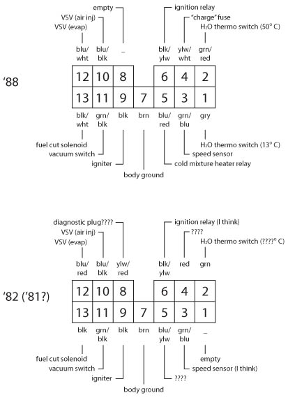
Below is an image of how I can best figure out the pin assignments for the Emission Control Computers for both the '82 ('81), and the '88.
For that matter. does anyone have a bona fide '82 (or '81) wiring diagram and/or FSM "Component Layout and Schematic Drawing" for emissions (shows wiring harness pins).
Thanks a lot for any help.
I'm trying to figure out where the red #4 pin and blue/yellow #5 pin go from the '82 Emission Control Module.
I should note that the truck was manufactured in 09/81, and the Emission Control Computer has "'81 22r Federal" stamped on it.
I've looked at the <'85 manual and wiring diagram, but the wiring is clearly a little bit different than the '82, as the pin assignments and wire colors are different. This '82 ('81) engine does not have a cold mixture heater, and nor do I see any "charge" fuse. There is no relay/fuse box in the engine compartment.
Below is an image of how I can best figure out the pin assignments for the Emission Control Computers for both the '82 ('81), and the '88.
For that matter. does anyone have a bona fide '82 (or '81) wiring diagram and/or FSM "Component Layout and Schematic Drawing" for emissions (shows wiring harness pins).
Thanks a lot for any help.
Nov 6, 2013 | 01:03 PM
#3
Thread Starter
Registered User
Joined: Feb 2010
Posts: 18
Likes: 0
I'm trying to put this '88 ECC (along with its engine) in the '82 and I want to make sure I've got the wires in the '82 harness going to the right places so I don't blow it out or something. Plus, I'm trying to keep the '88 engine in stock config.
Last edited by TheTinSoldier; Nov 6, 2013 at 01:05 PM.
Nov 7, 2013 | 08:00 AM
#5
From what I can tell from my wiring diagram, here is what I think:
on 82 ECC diagram above
#4 pin (Red wire) goes to OC Thermo Sensor (Cat Converter). The other side of the sensor goes to Pin #8 (yellow/red wire) on the ECC connector
#5 pin (blue/yellow wire) goes to EVAP Purge VSV#3. The other side of the valve goes to pin #12 (Blue/Red) on the ECC connector
#6 pin (Green/red wire) goes to Thermo sw#2 to ground
#1 pin is blank
On the 88 diagram, the #4 pin goes to Charge Warning Light
Last edited by Lons81; Nov 7, 2013 at 08:07 AM.
Nov 8, 2013 | 08:21 AM
#6
Thread Starter
Registered User
Joined: Feb 2010
Posts: 18
Likes: 0
Thanks a lot. I think this will be helpful all along the way with this project, but I noticed that a few of the wires in that diagram are different from what I've got as well. The wires that I have figured out, I'm pretty sure about, as I've continuity tested for them.
I have made a little headway, though. It looks like the red #4 pin also goes to the same diagnostic/unused plug on the driver's side of the engine compartment that the yellow/red #8 pin leads to (see image).
Still looking for where the blue/yellow #5 pin goes, but I can see that it leads up toward the dash rather than out toward the engine compartment. I'm hoping to avoid having to take out the cluster and tear into the harness up there.
Nov 8, 2013 | 11:48 AM
#7
I have been looking at the wiring diagrams I have from Autozone and the blue/yellow (for an 1983 22R) appears to be a hot wire (12V power) that runs to all the sensors like the VSV, EACV, Fuel-Cutoff solenoid, etc. It comes from a 7.5 amp fuse somewhere and runs to all the sensors but also runs to an input on the computer, I assume to power the computer. It doesn't give me a terminal number but maybe this will help. It also shows a yellow/red wire that went to the charge light relay which also runs to the driver side of the engine bay where the voltage regulator should be. As for the red wire it shows it running to s TWC sensor (California version). Not sure what TWC is though.
Here is the picture:
[IMG]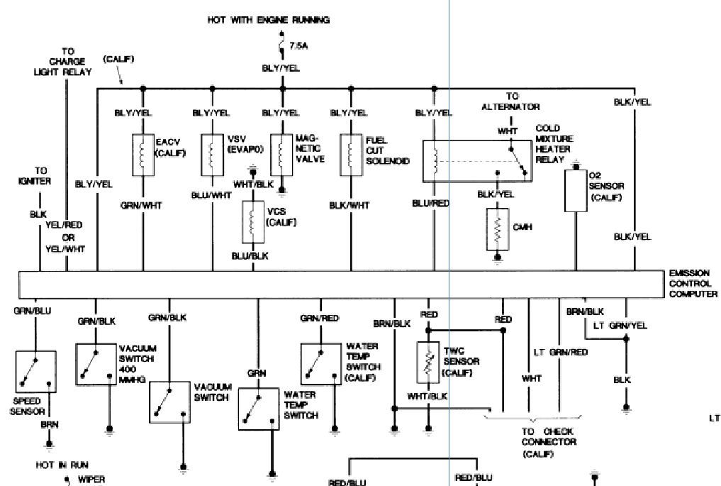 [/IMG]
Hope this helps.
Here is the picture:
[IMG]
 [/IMG]
Hope this helps.
Trending Topics
Nov 8, 2013 | 02:47 PM
#8
Thread Starter
Registered User
Joined: Feb 2010
Posts: 18
Likes: 0
I have been looking at the wiring diagrams I have from Autozone and the blue/yellow (for an 1983 22R) appears to be a hot wire (12V power) that runs to all the sensors like the VSV, EACV, Fuel-Cutoff solenoid, etc. It comes from a 7.5 amp fuse somewhere and runs to all the sensors but also runs to an input on the computer, I assume to power the computer. It doesn't give me a terminal number but maybe this will help. It also shows a yellow/red wire that went to the charge light relay which also runs to the driver side of the engine bay where the voltage regulator should be. As for the red wire it shows it running to s TWC sensor (California version). Not sure what TWC is though.
Here is the picture:
Hope this helps.
Here is the picture:
Hope this helps.
That yellow/white one is on the '88 connector at that same place (#4 pin) and goes to the charge light relay, but again this one ('82/'81) doesn't seem to have a charge light relay, and I did find that the red #4 pin wire goes to a capped off diagnostic plug or something (see my last post).
Still can't figure that blue/yellow at #5 pin that seems to go up into the dash!
Nov 8, 2013 | 03:22 PM
#9
Unfortunately I think that the BLY was a misprint and actually should say BLK. The other blue wires are marked BLU, and the right side of those traces says BLK/YEL.
That yellow/white one is on the '88 connector at that same place (#4 pin) and goes to the charge light relay, but again this one ('82/'81) doesn't seem to have a charge light relay, and I did find that the red #4 pin wire goes to a capped off diagnostic plug or something (see my last post).
Still can't figure that blue/yellow at #5 pin that seems to go up into the dash!


Thread
Thread Starter
Forum
Replies
Last Post
86 87 4Runners
84-85 Trucks & 4Runners
10
Sep 5, 2015 06:02 AM
86 87 4Runners
86-95 Trucks & 4Runners
3
Sep 2, 2015 03:54 AM


