When you click on links to various merchants on this site and make a purchase, this can result in this site earning a commission. Affiliate programs and affiliations include, but are not limited to, the eBay Partner Network.
I meant the tiny mouser part.
So, resistor soldered in, re-plugged and installed.
Re-installed the new 5-pin relay. (still fuel in filter from 5 sec bypass trick last week)
Turned and turned and no new fuel to the filter/carb.
If the bypass worked, could it be the relay? I tested it earlier and it closed when energized.
Seemingly the pump works, but I'm not fully convinced now......
This is how far I got and then I gave up. I'm not getting the 9.8V coming out of the BY wire to the relay. My relay was also clicking and is engaging but no pump. I just have it hard wired in from a 12v power source from the lighter. It sucks but the truck is drivable. I think there is a step we are missing. I also checked the oil sensor and I was getting a reading out that.
Thanks for your response.
I put my tester on the BY wire of the female relay plug and cranked, got 8.8v.
Is that enough to start the pump? (Seems not)
Too much resistance?
I do not voltage to the lighter plug either.
Is there another way to get power to the pump ???
After the 5 sec success I think it must still work....
Still trying
R
8.8 volts is good enough to run the fuel pump in "run" conditions, meaning with sufficient oil pressure to open the oil sender. Ideally & according to my calculations, running voltage thru the fuel pump resistor should be 9.5 volts, but 8.8 is enough for the pump to run & provide correct fuel pressure & volume.
What you need to understand here is that the fuel pump gets power in two different ways, depending on conditions. With no oil pressure, the relay is switched over to the "start" circuit. This provides full battery power to the fuel pump for starting. Once the engine starts, or builds enough oil pressure from cranking without a start, the oil sender opens, deenergizes the relay coil, and the contact arm goes back over to the "run" circuit, which has the resistor in circuit.
Yes the "5 second success" does prove that the fuel pump works. It also shows that the "start" side of the fuel pump circuit is good. The 8.8 volts on the BY wire proves that the relay is doing what it should.
Next I would test for full battery voltage at the BW (Black with White stripe) wire in the relay socket, with the ignition switch turned & held in cranking position If you have full battery voltage for that test you'll know the "start" side is good. If no voltage at all you have a power feed problem between the ignition switch & relay socket. It's rarely the truck's wiring in my experience but it may be possible that your "emissions computer" has an short in it and is causing a power feed problem. For testing purposes, unplug the "computer" to take it entirely out of the circuit & test again. The "computer" is located on the driver's side kick panel & should have a multi-wire plug in the top of it. It will not harm anything if you unplug it.
I am also going to post 2 pages here in a bit of a complete 1978 pickup wiring diagram for reference.
@nottoshabi I wish I had heard back from you about this so I could try to help. Check out my response to richdaze above from some things you can try & test.
Last edited by 13Swords; May 11, 2022 at 05:41 AM.
As promised, 1978 pickup wiring diagrams. These are original Toyota diagrams published by Mitchell. You'll have to download & save the file to your computer to view them. Any problems with this let me know & I'll try to figure something else out so they can be seen here.
Thanks again for continuing to respond, and for sending the diagrams. I would need them if I end up having this truck re-wired....I cannot believe that nothing is working.
Okay, the BW wire in the relay plug has 9.4v while cranking, with or without the computer plugged in. No other wire gets voltage. And now, the stereo doesn't light-up, and there is no v to the cig lighter. The stereo had previously ( for months) shown a "miswiring" msg, but always lit-up. The lighter plug functioned for my usb charger forever.
Certainly makes me wonder if I can keep the new parts (resistor and COR switch) and install and power-up a frame-mounted fuel pump to bypass this mess.
The inline filter still has fuel in it from my 5 sec success story. The tank is still full.
@richdaze I always try to do the best I can. I'm just sorry this thing has currently got you snookered. It's starting to sound like either you have a previous owner that messed with the wiring, or the rodents have been at work on the wires sometime in the past. Or maybe a few other problems to boot.
The BW wire is a direct connection to your ignition switch "start" circuit. The 9.4 volts here is concerning me a bit. As a rule of thumb, battery voltage does drop during cranking, but typically it's around 10.5 volts. Why this is happening could be any number of things, like a worn starter or starter solenoid contacts drawing more power than normal. But even 9.4 volts should be enough to run the pump OK. When you say it's the only wire getting voltage, do you mean during cranking? Is your oil light staying on during cranking, or does it go out after some seconds of cranking?
I ask this last part because on a "cold crank" (cold engine with no oil pressure), the presence or lack of voltage coming from the oil sender controls the coil in the relay, and that determines through which circuit, the start or the run circuit, the fuel pump gets voltage from.
Here's the fuel pump diagram again so I can try to make this make sense.
Look at the relay. It is shown in a "resting" position, or with the relay's coil un-energized. This allows voltage to come through the "run" side of the ignition switch, through the relay & to the fuel pump, as long as there is good oil pressure (oil light off) & the ignition switch is in the "run" position. When there is no oil pressure, the oil pressure sender switch is closed, & sends voltage to the relay's coil. This moves the pole over to the "start" side of the relay, and allows voltage to come in from the start side of the ignition switch, until oil pressure is built up from cranking or from an engine start. Then the pole in the relay flops back over to the "run" side as shown. So, depending on presence or lack of oil pressure, & position of the ignition switch, voltage can go to the fuel pump one of two ways.
If you put the ignition switch to "run", you should see voltage on the BY wire of the relay connector, and it should be around 9.5 volts. You should only see voltage on the BW wire while cranking & before the engine generates sufficient oil pressure.
The oil pressure thing also explains why you only got those 5 seconds of fuel flow on your previous test.
Now for something completely different. How hard of a look have you had at your fuse block? I don't mean just fuses, the whole thing. I ask this because when I was fighting my battles with this modification, it occurred to me to have a long & hard look at the fuse block. In my case, I found a pretty fair amount of green copper oxide on many of the backside terminals, including on terminals that fed the start & run circuits. That could have caused some connection problems or higher resistance problems. Given a 40+ year old truck, I should expect these things. Maybe you have something like this going on but can't see it, because the terminals are on the backside of the block? And maybe this is at least part of the cause of the electrical feed issues?
There could also be that oxide inside the connector plug on the back of the fuse block.
I ended up removing mine from the truck & manually cleaning everything with pencil erasers & 0000 steel wool, but in hindsight I should have just gotten some regular Tarn-x & dipped the block & connectors. That stuff almost instantly removes copper oxide with no damage.
This could also be the problem with the radio & lighter plug.
Since all the voltage for everything comes from there first (battery excluded) I would recommend you take it out & have a look. It's not difficult, two fair-sized connectors on the back with retaining clips (don't break these!) & 2 bolts holding the block to the dash.
Sorry if it seems I'm running you around in circles here but that's certainly not my intent. With these old trucks I've learned you have to look at everything in a system in order to get it working right again.
Whether you go with a frame-mounted pump or not is up to you. People used to do this in the older days when the stock pump or COR failed, because the COR (when you could still get them then) were not cheap, nor were the stock-style in-tank pumps.
They'd just find a pump that gave 5/8 PSI for the stocker carb, wired it into the ignition circuit & called it good.
I just went through the effort of trying to keep mine functional stock because I wanted to keep the designed safety of it. Plus I know that the stock-style stuff tends to last longer than those frame-mounted pumps. And there is no way I want to do mine again.
Okay, I am following your informative "circles", and they are once again greatly appreciated.
And I am also a fan of keeping vehicles as stock as possible, when possible.
However, now with fuse block cleaned, brushed and dielectric greased, (no corrosion, just dust), crank tested w/wo computer, replaced lighter fuse, oil-light out upon cranking, and still no new fuel.
I am ready to modify, as I use this RV numerous times a year.
Should an exterior pump use it's own switch? In-line fuse? And should the 12v circuit to this pump run thru a key-on- only fuse in the box, or one like the lighter, that is hot all the time?
Thanks again R
I will never argue with anyone who does what they need to do to make it work, as long as it's safe.
Of course you can put an exterior pump on it's own switch & manually turn it on & off as needed. The only reason to run such a pump thru a key-on only circuit is to be sure it isn't sitting there running when the engine isn't. Even the best of us can forget to turn the thing off, but we always shut down the engine when we're done driving, so a keyed power circuit makes the most sense to me. Up to you but I wouldn't run one on a constant hot without a shut-off switch.
Guys in the "old days" used to just wire the pump up to the ignition coil power circuit, as the coil gets power in both the start & run circuits. I did this with my HEI Ignition Module conversion and it works fine.
Only other things I know about this:
Mount the pump as close to the tank as possible. Electric pumps are known to "push" better than they "draw" so keeping it close to the tank will help the pump work well.
DO NOT mount the pump in the engine compartment. Aftermarket electric pumps really don't seem to like underhood heat & die quickly that way, in my experience. It's also a fire hazard.
I would use an in-line fuse & at least 16 gauge wire. Most aftermarket pumps draw 3-5 amps & 16 gauge is rated for 22 amps, so that gives you a 4 to 1 safety margin. If the pump ever locks up or a malfunction causes the pump to draw higher current, the in-line fuse will save the rest of your wiring.
If running a manual shut-off switch, I'd get one that's rated for 15 amps. Again, this is for a safety margin & to make sure the circuit runs cool.
I don't have any recommendations on brands of aftermarket electric fuel pumps but the spec you'll need for a fuel pump is 5-8 PSI & about 32 GPH (gallons per hour). This is based on using the stock carb.
I will continue to use your advice, and thanks again.
While I have test lights, meter, cleaning tolls, trouble light all handy, can you think of any other bypass test tricks, or alternate power delivery methods, or anything at all I can do before I jack it up ??
It seems so close to activation; some crucial link is obviously missing.
To be continued............R
Don't know if I mentioned this before or not, but you could try running a jumper wire direct from battery positive to the Black/Red wire terminal in the relay connector. This would directly power the fuel pump from the battery, eliminating the resistor & relay setup. It would at least confirm if the pump is the issue or not, & whether or not it has continuous function. If it were me I'd also disconnect the fuel feed hose on the truck near the tank, & put a long "test length" of fuel hose on it & run it to a gas can as well. That way I can see for sure if it's got constant flow or not, & also check the flow rate. This should be enough to confirm or discount the pump as a problem. A minute or so of full battery power shouldn't hurt the pump if it's in good condition.
The other bypass I did tell you about, with jumpering the connector for the fuel pump resistor, is also valid. But this method would include almost the entire circuit e.g. ignition switch, oil sender, & relay; plus the wires feeding all those. Only the resistor would be eliminated for testing, This is going to require your turning the key to crank it over to test voltage(s) from the relay. You'd also have to deal with the usual 5 seconds of pump running on the "start" side of the relay, before the oil sender switch "switches over" the relay from the "start" side to the "run" side. I guess if your meter has a probe for at least the positive side, you could probe the Black/Red wire terminal in the fuel pump relay connector, with the relay still connected. Once the relay "switches over" after oil pressure is built, you should see voltage on that wire. IF everything is working correctly. Don't forget you need to connect your negative probe/clip to a good ground for all this.
if you crank & the oil light goes out but still see no voltage, it would have to be a feed problem somewhere before the relay. This could be a wire issue somewhere.
I'd also suggest probing the White/Blue wire terminal in the fuel pump relay connector with the ignition switch on "run" & with the negative probe grounded.
You could also probe the Black/Red connector terminal for continuity to ground thru the fuel pump to check for good ground.
Fuel pump resistance should only be a few Ohms at most, but keep in mind you're measuring a pretty big "loop" circuit here. Wire all the way to pump then pump grounded to tank & that ground all the way back to where you ground your negative probe. So that OHM spec could be higher than stated here. It would be best to resistance test the fuel pump at the connector & a ground point on the tank. But you have to drop the tank to get at that.
You could also probe the Black/White wire terminal in the relay connector to see if you're getting battery power from the "start" side of the ignition switch when turned to "start" (crank).
I can't think of much else right now. I agree with you, there is probably just one small thing keeping this system from working the way it should.
Hooray! Jumped to the B/R, then could HEAR the buzz, then SEE the fuel come to the filter near the carb, and THRU the test hose into the gas can!
Seems like a steady flow, and let it run for 2- 15 sec tests. Same result. Pump works.
It still stumps me as to how to cut the volts to the proper operating amount. Can I splice a hot wire into the relay switch? Into the resistor itself?
So glad I talked w/you again before purchasing pump/wire/switch/fuse/clamps/ etc.
So ready to finish this correctly ---
R
Don't know if I mentioned this before or not, but you could try running a jumper wire direct from battery positive to the Black/Red wire terminal in the relay connector. This would directly power the fuel pump from the battery, eliminating the resistor & relay setup. It would at least confirm if the pump is the issue or not, & whether or not it has continuous function. If it were me I'd also disconnect the fuel feed hose on the truck near the tank, & put a long "test length" of fuel hose on it & run it to a gas can as well. That way I can see for sure if it's got constant flow or not, & also check the flow rate. This should be enough to confirm or discount the pump as a problem. A minute or so of full battery power shouldn't hurt the pump if it's in good condition.
The other bypass I did tell you about, with jumpering the connector for the fuel pump resistor, is also valid. But this method would include almost the entire circuit e.g. ignition switch, oil sender, & relay; plus the wires feeding all those. Only the resistor would be eliminated for testing, This is going to require your turning the key to crank it over to test voltage(s) from the relay. You'd also have to deal with the usual 5 seconds of pump running on the "start" side of the relay, before the oil sender switch "switches over" the relay from the "start" side to the "run" side. I guess if your meter has a probe for at least the positive side, you could probe the Black/Red wire terminal in the fuel pump relay connector, with the relay still connected. Once the relay "switches over" after oil pressure is built, you should see voltage on that wire. IF everything is working correctly. Don't forget you need to connect your negative probe/clip to a good ground for all this.
if you crank & the oil light goes out but still see no voltage, it would have to be a feed problem somewhere before the relay. This could be a wire issue somewhere.
I'd also suggest probing the White/Blue wire terminal in the fuel pump relay connector with the ignition switch on "run" & with the negative probe grounded.
You could also probe the Black/Red connector terminal for continuity to ground thru the fuel pump to check for good ground.
Fuel pump resistance should only be a few Ohms at most, but keep in mind you're measuring a pretty big "loop" circuit here. Wire all the way to pump then pump grounded to tank & that ground all the way back to where you ground your negative probe. So that OHM spec could be higher than stated here. It would be best to resistance test the fuel pump at the connector & a ground point on the tank. But you have to drop the tank to get at that.
You could also probe the Black/White wire terminal in the relay connector to see if you're getting battery power from the "start" side of the ignition switch when turned to "start" (crank).
I can't think of much else right now. I agree with you, there is probably just one small thing keeping this system from working the way it should.
Hey 13 Swords, A sincere thanks to you for all of the suggestions and advice.
I followed them all (most)and we agreed that it was one SMALL THING!
After checking all fuses (vis only) and pulling the fuseblock (great suggestion but no corrosion), and finally having an auto elec tech put his eyes and machines on it, it turned out that 2 of the glass tube fusses, (possibly very old) had loose end caps, preventing voltage passing thru..
I was happy and relieved that there was no pump/sender/wiring/etc issues !!
Thanks again for your great help.
Rich
I'm glad it was something simple but, damn, who ever expects that problem? I've also come across a few fuses like that in my day, but it's few & far between, so I didn't think of it to mention it. Who ever thinks about a glass body fuse "wearing out"?
Glad to hear the rest of the system is functioning properly. Good news here is that since you've been thoroughly thru the system it should continue to function without problems for a long time. I'm going on year 7 of going thru mine and it's working perfectly. Good job on being persistent with it.
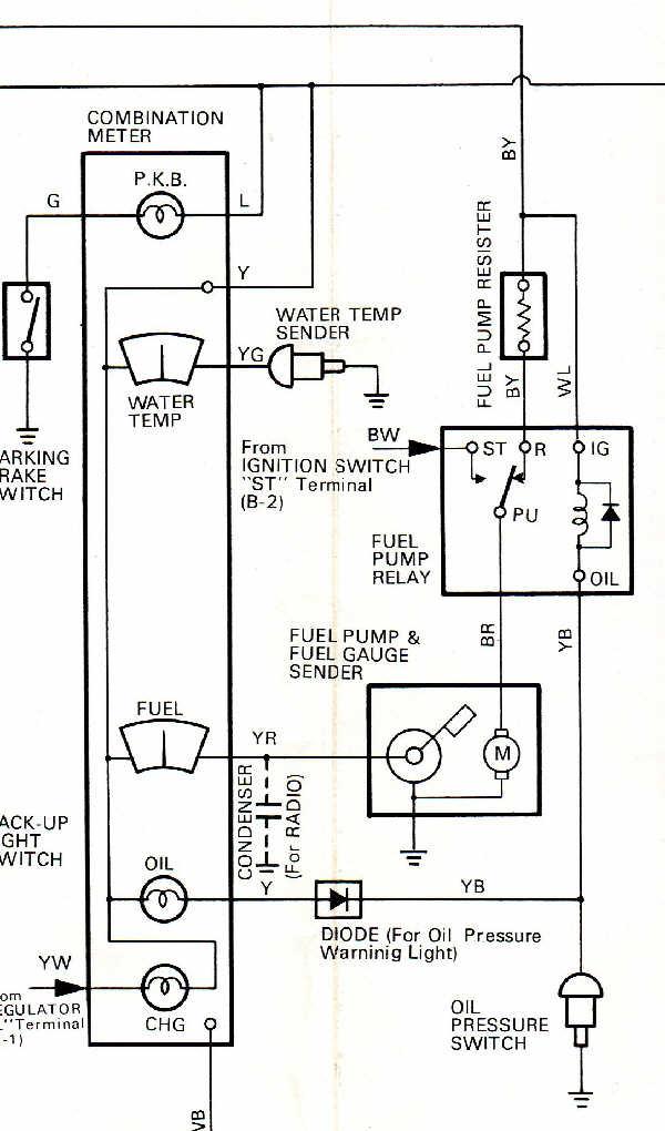
I had this diagram on file but thought it might be helpful to some out there, plus some info on rehabing the electric fuel pump circuit/system. This is the wiring diagram for the electric fuel pump circuit on 1975 to 1978 Pickups. It might also apply to 1979 to 1981 pickups with the 20R and electric fuel pump in the gas tank, and 1982 to 1984 & up 22R carbureted engines (NOT EFI). It might also apply to other models of the same era/years with the 20R engine, like the Celica or Corona. The wire colors below are for the Pickup; wire colors on other models may differ.
Wire Color Codes:
B - Black
W - White
Y - Yellow
G - Green
L - Blue
R - Red
BR - Brown
Wire Color with 2 Letters - 1st letter is the overall color of the wire, 2nd letter is the "stripe" color. Example: BR - Black with Red Stripe, WL - White with Blue Stripe, etc.
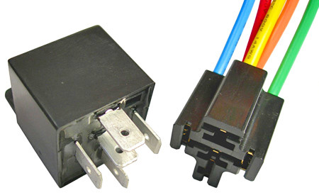
This diagram came in very handy for me when trying to rehab my fuel pump electric system. Original style fuel pump relays & resistors are no longer available from Toyota for the '75 to '78. I used a standard Bosch style 5 pin relay rated at 30-40 Amps & a wired socket as a replacement & it works fine. The Bosch style relay & wired socket look like this:
Electrically, the Toyota relay & the Bosch style relay operate the same way. I crimped on some female sockets to the ends of the wires on the wired socket & plugged each onto the male lugs in the original socket on the wire harness located under the center dash. This way I didn't have to hack up the original harness & retained the original plug. You could of course cut off the stock relay socket & splice in the Bosch style wired socket; that's up to you to decide. With the diagram it was hard to go wrong. All Bosch style relays will have a number next to each terminal pin. The pinout I used was:
Relay terminal to Stock Wire Color
85 - YB - Yellow w/Black Stripe - Oil Pressure Switch
86 - WL - White w/Blue Stripe
30 - BR - Black w/Red Stripe - Fuel Pump
87A - BY - Black w/Yellow Stripe - "RUN" from Ignition Switch, Fuel Pump Resistor
87 - BW - Black w/White Stripe - "START" from Ignition Switch
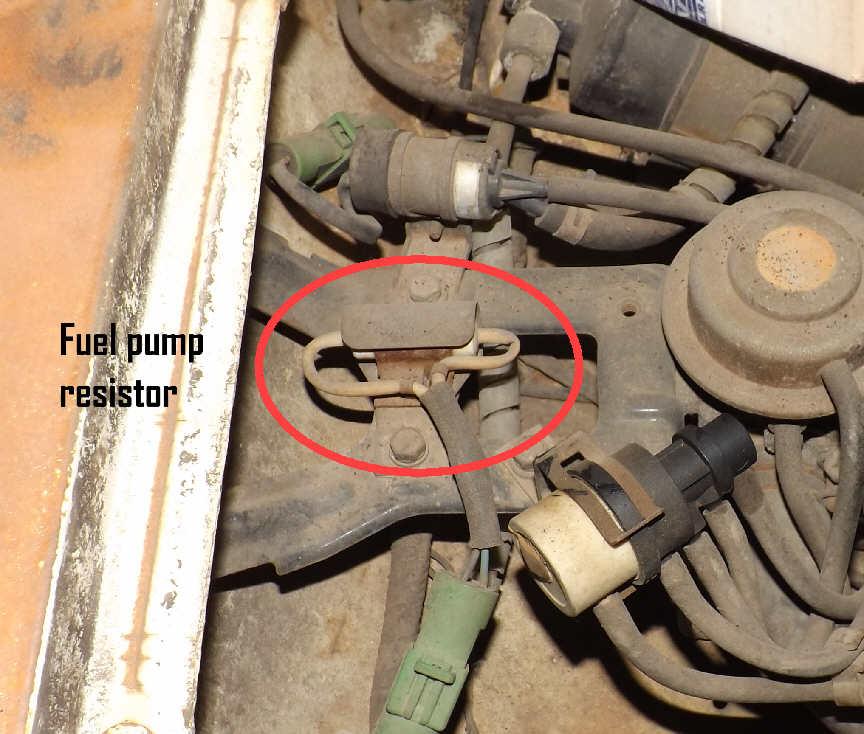
As for the resistor, the stock one was a ceramic power resistor rated at 1.4 Ohms and 10 Watts. Over time & with heat cycling the resistor can fatigue & get out of spec, especially when hot. It might measure/test fine with an Ohm meter "cold" but once it heats up the resistance will rise to a point where it "chokes off" a good deal of the voltage going to the fuel pump. My resistor measured exactly 1.4 Ohms cold, but when heated with a hair dryer it spiked up to 2.8 Ohms after only a few minutes. The tolerance on one of these working resistors shouldn't be anything beyond 10% (1.54 Ohms), so it definitely needed replacing.
I used a new aluminum cased power resistor in place of the old one and it works great. I installed it under the hold-down tab on the stock mounting plate & soldered it onto the stock wires. The resistor is located in the engine compartment, on top of the passenger side wheel well. Here are a few representative pics (they are not my exact parts, but posted to give you an idea of what they look like):
The resistor I used was from Mouser Electronics, who will let you order just the one piece, or sometimes you can find them at your local electronics shops. It looks like this:
Specs:
Manufacturer: ARCOL/Ohmite
Manufacturer Part # HS10 1R5 F
Mouser Part # 284-HS101.5F
1.5 Ohms, 10 Watts, 1% Tolerance
These resistors are military spec, moisture proof and are temperature rated from -67 degrees to 392 degrees F, so it's going to survive very well in an engine compartment. The aluminum case also acts as a heat sink so the resistor can easily get rid of any internal heat. The 1.5 Ohm rating is not exact to the stock 1.4 Ohms but it works fine. Pump volume does not suffer any. If you go looking for one of these resistors locally but can't find the exact spec, I recommend you keep it between 1.4 Ohms & 1.8 Ohms and at least 10 Watts; 20 or 25 Watts is fine as well, it'll just handle the power better with less internal heat. I've literally done DAYS of math on these, doing voltage drop calculations based on the different Ohm ratings, and considering the pump specs, the 1.4 to 1.8 Ohm range will work with no problems. Just do NOT go below 1.4 Ohms or you risk damaging your pump.
Depends on the oil pressure condition of the engine; whether oil pressure is present or not. The relay's coil is operated by the oil pressure sender switch, which is a "normally open" switch when oil pressure exists (engine running). In that condition, the coil in the relay is not energized, and the pole would be resting on the RUN side (terminal 87A). This is the condition shown in the wiring diagram.
When engine oil pressure drops (engine not running), the oil pressure sender switch closes, which energizes the relay's coil, which forces the pole to connect to the START side (terminal 87). In that condition (no oil pressure), the oil pressure sender switch is "normally closed".
So it's not the relay which can be called normally open or normally closed, it's the oil pressure sender switch, and then only depending on whether there is oil pressure affecting it or not. Basically & operationally speaking, engine running it's open, engine not running it's closed.
In an effort to make all this make more sense, I'll explain what Toyota had in mind here. This relay system serves 2 purposes.
1. Quicker Cold Starting. For "cold starts" this system allows the relay to send full direct battery voltage (12 volts+) to the fuel pump (Black/White for Ignition Switch START to Black/Red Fuel Pump voltage feed. This bypasses the fuel pump resistor, so the fuel pump can provide peak fuel pressure & volume to the carburetor. This allows for quicker cold starts. Once the engine starts & the oil pump generates sufficient oil pressure, the relay switches the voltage feed to the fuel pump back to the circuit with the fuel pump resistor (Black/Yellow for Ignition Switch RUN to Black/Red Fuel Pump voltage feed). The Fuel Pump Resistor drops the battery voltage down to about 9.5 to 10 volts to the fuel pump, which is the normal "running voltage" the pump was designed for. The pump supplies the normal running pressure & volume, runs quieter, and lasts longer.
2. Crash Safety Feature. Let's say the vehicle crashes & the driver is knocked unconscious. Let's also say that a fuel line breaks in the crash. The engine is either going to stall out from a crash or stop running from a lack of fuel. But the fuel pump is still running & pumping out raw fuel through that broken line. BIG fire hazard, and if that fuel finds an ignition source, the unconscious driver could be burned alive. Not good.
But with this relay system in place, the stopped engine loses oil pressure & stops voltage flow to the pump. Even with the key/ignition switch still in the RUN position. With no oil pressure, the relay "flops" the pole back over to the START side, & someone would have to manually turn the key to START to send any voltage to the pump.
hello! Could you tell me where the fuel pump relay is located? I hope it�s not on the dashboard 🤞 of my 1977 Toyota pickup.
thank you in advance
Originally Posted by 13Swords
I had this diagram on file but thought it might be helpful to some out there, plus some info on rehabing the electric fuel pump circuit/system. This is the wiring diagram for the electric fuel pump circuit on 1975 to 1978 Pickups. It might also apply to 1979 to 1981 pickups with the 20R and electric fuel pump in the gas tank, and 1982 to 1984 & up 22R carbureted engines (NOT EFI). It might also apply to other models of the same era/years with the 20R engine, like the Celica or Corona. The wire colors below are for the Pickup; wire colors on other models may differ.
Wire Color Codes:
B - Black
W - White
Y - Yellow
G - Green
L - Blue
R - Red
BR - Brown
Wire Color with 2 Letters - 1st letter is the overall color of the wire, 2nd letter is the "stripe" color. Example: BR - Black with Red Stripe, WL - White with Blue Stripe, etc.
This diagram came in very handy for me when trying to rehab my fuel pump electric system. Original style fuel pump relays & resistors are no longer available from Toyota for the '75 to '78. I used a standard Bosch style 5 pin relay rated at 30-40 Amps & a wired socket as a replacement & it works fine. The Bosch style relay & wired socket look like this:
Electrically, the Toyota relay & the Bosch style relay operate the same way. I crimped on some female sockets to the ends of the wires on the wired socket & plugged each onto the male lugs in the original socket on the wire harness located under the center dash. This way I didn't have to hack up the original harness & retained the original plug. You could of course cut off the stock relay socket & splice in the Bosch style wired socket; that's up to you to decide. With the diagram it was hard to go wrong. All Bosch style relays will have a number next to each terminal pin. The pinout I used was:
Relay terminal to Stock Wire Color
85 - YB - Yellow w/Black Stripe - Oil Pressure Switch
86 - WL - White w/Blue Stripe
30 - BR - Black w/Red Stripe - Fuel Pump
87A - BY - Black w/Yellow Stripe - "RUN" from Ignition Switch, Fuel Pump Resistor
87 - BW - Black w/White Stripe - "START" from Ignition Switch
As for the resistor, the stock one was a ceramic power resistor rated at 1.4 Ohms and 10 Watts. Over time & with heat cycling the resistor can fatigue & get out of spec, especially when hot. It might measure/test fine with an Ohm meter "cold" but once it heats up the resistance will rise to a point where it "chokes off" a good deal of the voltage going to the fuel pump. My resistor measured exactly 1.4 Ohms cold, but when heated with a hair dryer it spiked up to 2.8 Ohms after only a few minutes. The tolerance on one of these working resistors shouldn't be anything beyond 10% (1.54 Ohms), so it definitely needed replacing.
I used a new aluminum cased power resistor in place of the old one and it works great. I installed it under the hold-down tab on the stock mounting plate & soldered it onto the stock wires. The resistor is located in the engine compartment, on top of the passenger side wheel well. Here are a few representative pics (they are not my exact parts, but posted to give you an idea of what they look like):
The resistor I used was from Mouser Electronics, who will let you order just the one piece, or sometimes you can find them at your local electronics shops. It looks like this:
Specs:
Manufacturer: ARCOL/Ohmite
Manufacturer Part # HS10 1R5 F
Mouser Part # 284-HS101.5F
1.5 Ohms, 10 Watts, 1% Tolerance
These resistors are military spec, moisture proof and are temperature rated from -67 degrees to 392 degrees F, so it's going to survive very well in an engine compartment. The aluminum case also acts as a heat sink so the resistor can easily get rid of any internal heat. The 1.5 Ohm rating is not exact to the stock 1.4 Ohms but it works fine. Pump volume does Hello!not suffer any. If you go looking for one of these resistors locally but can't find the exact spec, I recommend you keep it between 1.4 Ohms & 1.8 Ohms and at least 10 Watts; 20 or 25 Watts is fine as well, it'll just handle the power better with less internal heat. I've literally done DAYS of math on these, doing voltage drop calculations based on the different Ohm ratings, and considering the pump specs, the 1.4 to 1.8 Ohm range will work with no problems. Just do NOT go below 1.4 Ohms or you risk damaging your pump.
hello! Could you tell me where the fuel pump relay is located? I hope it�s not on the dashboard 🤞 of my 1977 Toyota pickup.
thank you in advance
On the 1975 to 1978 models, the Fuel Pump Relay is under the dash, usually somewhere to the right (passenger side on US trucks) of the steering column. It is reasonably accessible without having to tear the dash apart. Look in the area under where the radio would be.
OK! My name is John and I hunted down this thread because I needed the expertise.
I have read it over several times, and the particular issue I'm having isn't quite covered here
I'll just dive right in saying that the resistor in the pump circuit is getting hot.
Like fry up your breakfast hot.
I bought the little resistor from Mouser, as was suggested, and it gets hot, too.
Like melt the Aluminum casing hot.
I set up a temporary hot wire from the battery to the pump, with a switch. The pump runs wide open.
I place the resistor in line on the temporary circuit, and it runs as one would expect it to run on the lower voltage, but overheats within 30 seconds or so and quits passing enough energy to run the pump.
MY GUESS is that the fuel pump has malfunctioned or there's a rogue ground in play.
I have a pump on the way, but If anybody has a thought that it may not be the pump, I'm all ears.

 May 7, 2022 | 07:50 PM