
Wiring Diagram explanation
 08-16-2009, 08:13 AM
#1
Registered User
Thread Starter

Join Date: Aug 2009
Location: Norway - Bodoe
Posts: 20
Likes: 0
Received 0 Likes
on
0 Posts
Wiring Diagram explanation
Hi
I have an easy question for you guys.
My wiring diagram is in english and my language is norwegian = don't understand everything.
On the wiring diagram alternator it reads L - B - S and IG, what says ?
I'm trying to wire my alternator, as there was a 3Y engine in it before and now there is a 22re.
But in the meantime there was a V8, and alot of cutting and crap has been done = big mess in the fusebox on the right fender.
 08-16-2009, 08:14 AM
#2
Registered User
Thread Starter
Join Date: Aug 2009
Location: Norway - Bodoe
Posts: 20
Likes: 0
Received 0 Likes
on
0 Posts
If anyone have a picture of this box, inside and underneath it would have been GREAT :
Also, how big is the black and green fuse here ? I can see the red one is 30A.
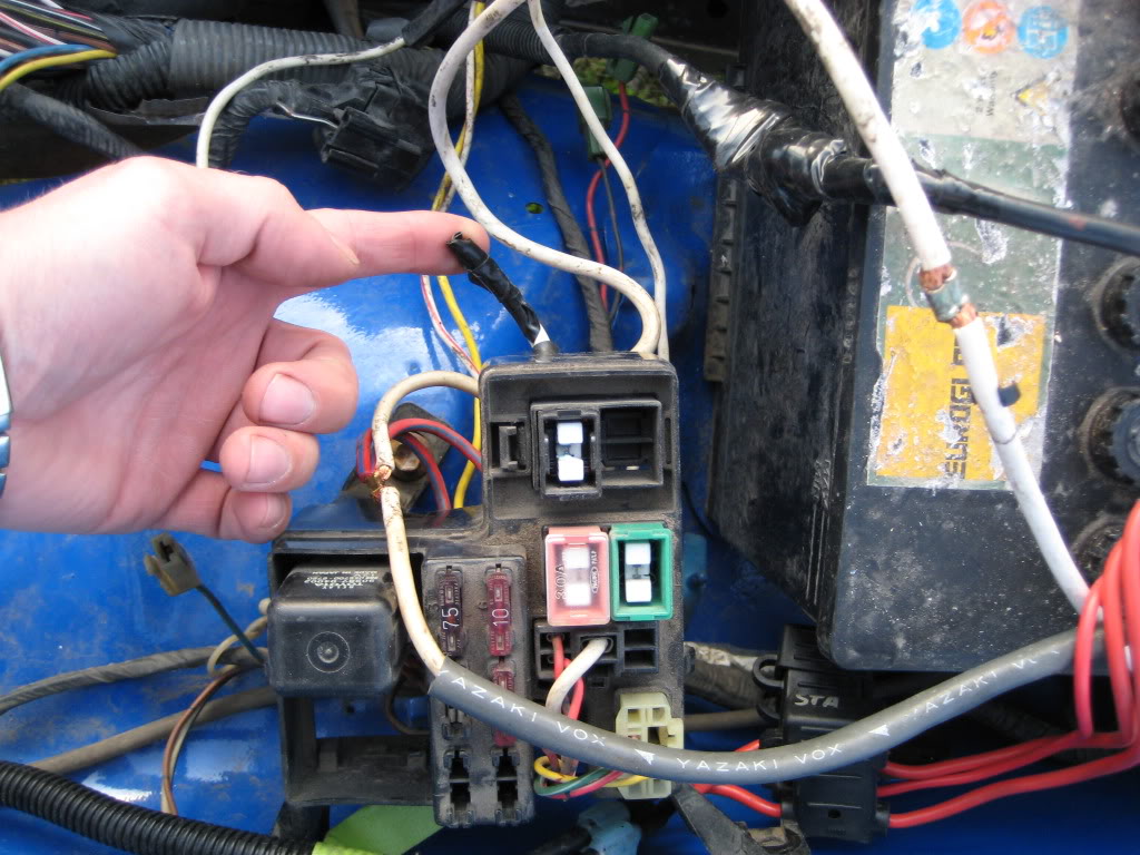
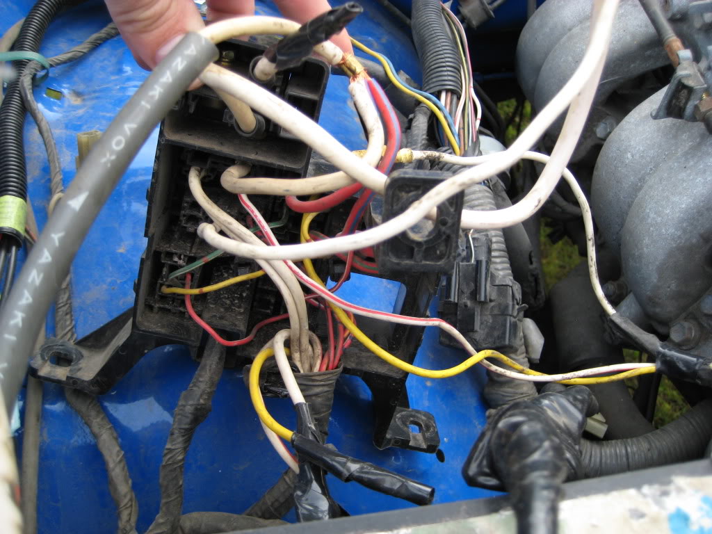
Underneath :
Also, how big is the black and green fuse here ? I can see the red one is 30A.
Underneath :
08-16-2009, 01:32 PM
#3
wow that is a mess if possible if you have the time get the Toyota Electrical manual for the year you have . If you can get one over there.
Your other option is to get a engine harness that is all in one piece no matter it is going to be a slow process
good luck
Your other option is to get a engine harness that is all in one piece no matter it is going to be a slow process
good luck
08-16-2009, 05:33 PM
#4
Registered User

Join Date: Sep 2007
Location: San Francisco East Bay
Posts: 8,254
Likes: 0
Received 822 Likes
on
649 Posts
IG is ignition (+12volts when key is on). L is to the alternator light. At ground when the alternator is not turning, 12v when turning and producing power. B is the separate heavy-gauge wire that is the output of the alternator. It goes directly to the battery through an 80amp fuse. S (which I believe 'means' stator) is to the B line, through a 40amp fuse. It supplies the 12v from the battery to the stator, which allows the alternator to produce power.
IG, L and S are in one connector at the alternator, B is a separate line to the copper stud.
On my 1994 v6, I have four "big" fuses; the 80 and 40 referred to above, and two 30s for the heater fan and the "AM2" circuit.
Your fuse box appears different from mine; you'll find better help here if you specify your year and engine size (though I realize, in your case, things may have been changed around a lot).
Good luck, and welcome to Yotatech.
08-16-2009, 07:13 PM
#5
Registered User
Join Date: Mar 2008
Location: Temecula Valley, CA
Posts: 12,723
Likes: 0
Received 4 Likes
on
4 Posts
Without seeing what you have... that makes it difficult.
The alternator should have a post connection and a 3-wire plug. The post connection is a heavy gauge white wire which goes to the battery. In the 3 wire plug should be another smaller white wire (which is parallel to the heavy white wire) and should have battery voltage all the time, a yellow wire which interfaces with the charge light on the dash, and a red wire which is hot (has 12v) with the key on.
The alternator should have a post connection and a 3-wire plug. The post connection is a heavy gauge white wire which goes to the battery. In the 3 wire plug should be another smaller white wire (which is parallel to the heavy white wire) and should have battery voltage all the time, a yellow wire which interfaces with the charge light on the dash, and a red wire which is hot (has 12v) with the key on.
08-16-2009, 09:18 PM
#6
Registered User
Join Date: Mar 2007
Location: Phoenix, Arizona
Posts: 680
Likes: 0
Received 0 Likes
on
0 Posts
heres the pirate thread abe, its a 85 hilux he says.
http://www.pirate4x4.com/forum/showthread.php?t=812073
http://www.pirate4x4.com/forum/showthread.php?t=812073
08-17-2009, 04:07 AM
#7
Registered User
Thread Starter
Join Date: Aug 2009
Location: Norway - Bodoe
Posts: 20
Likes: 0
Received 0 Likes
on
0 Posts
Yes, its a 85 Hilux. Used to be a 3Y in it, but now there's a 22re. In between there was a V8. This is a half-finished project I have bought, and I'm trying to figure out what's been done and put it back together how its supposed to be.
Trending Topics
 08-30-2009, 02:09 AM
#12
Registered User
Thread Starter
Join Date: Aug 2009
Location: Norway - Bodoe
Posts: 20
Likes: 0
Received 0 Likes
on
0 Posts
Ok, finaly had time to look at this mess.
Apparently there has been a separate regulator, but now the regulator is part of the alternator. At least so I think as the alternator is brand new... is there anyway to tell if it's part of it ?
And what is the little difference in the wiring ?
Apparently there has been a separate regulator, but now the regulator is part of the alternator. At least so I think as the alternator is brand new... is there anyway to tell if it's part of it ?
And what is the little difference in the wiring ?
09-02-2009, 09:41 AM
#13
Registered User
Thread Starter
Join Date: Aug 2009
Location: Norway - Bodoe
Posts: 20
Likes: 0
Received 0 Likes
on
0 Posts
Bad response here, guess there is no one who bothers to look, but I just continue to throw out questions just incase someone does.
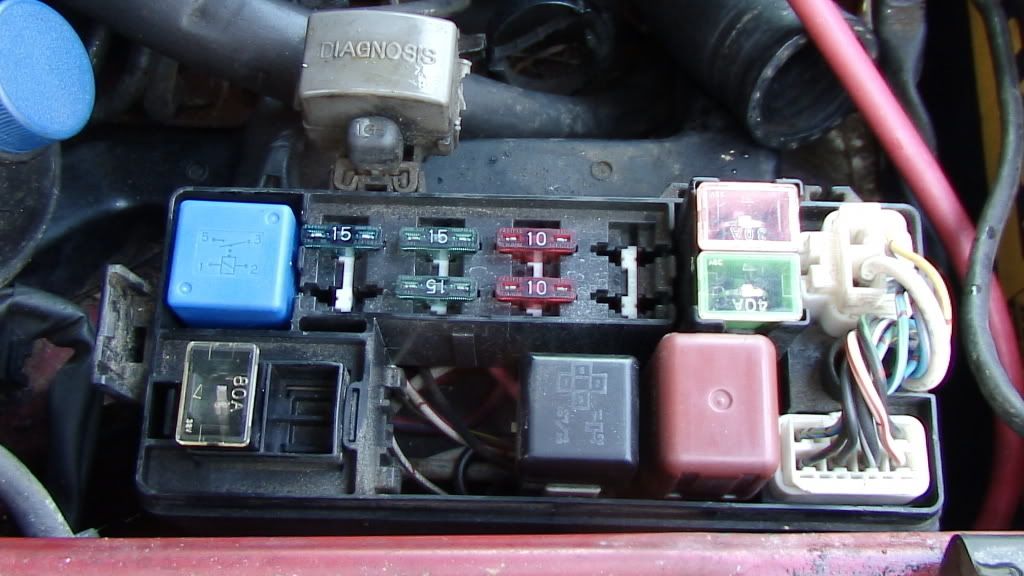
The pink 30A and the green 40A is linked/bridged, need to know the wires connected on the bridge side (where they lead to), can't figure it out from my wiring diagram.
The truck.

The pink 30A and the green 40A is linked/bridged, need to know the wires connected on the bridge side (where they lead to), can't figure it out from my wiring diagram.
The truck.
09-02-2009, 09:51 AM
#14
Contributing Member
Join Date: Apr 2008
Location: Colorado Springs, Colorado
Posts: 654
Likes: 0
Received 1 Like
on
1 Post
Wow thats pretty nice truck.Asd for the regulators are seperate, but they are putting them on the altenators (as afr as I know, don't quote me on this)Do you have teh diagrams for the truck? Here is a few sites. TIS is a pay site the other is free.
https://techinfo.toyota.com/techInfo....toyota.com%2F
http://www.ncttora.com/fsm/index.html
Hope this helps.
Edit: I just re-read your first post. Sorry
https://techinfo.toyota.com/techInfo....toyota.com%2F
http://www.ncttora.com/fsm/index.html
Hope this helps.
Edit: I just re-read your first post. Sorry
 09-27-2014, 04:03 PM
#17
Registered User

Join Date: Sep 2014
Posts: 1
Likes: 0
Received 0 Likes
on
0 Posts

Thread
Thread Starter
Forum
Replies
Last Post
theking11863
Vehicle Audio & Home Entertainment
2
03-19-2016 09:36 PM
88yodabasket
86-95 Trucks & 4Runners
15
07-13-2015 01:32 PM


