
early 3vze knock sensor wiring identification
 Feb 10, 2013 | 05:16 PM
#1

Thread Starter
Registered User
Joined: Nov 2012
Posts: 10
Likes: 0
early 3vze knock sensor wiring identification
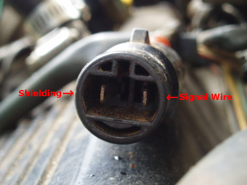
This is the engine harness side of the connection to the knock sensor pigtail. I will referr to the terminals as yellow and red per the picture below:

Kinda looks like a
anyway, If I shine a flashlight inside connector I can see the following markers
Yellow=6
Red=B3
My question is this: Which terminal is supposed to be the signal from the knock sensor and which one is the shielding ground? I am currently working on making an adapter from early style to late style (using an engine from a 91 in a 94 and don't want to butcher the harness). I removed the pins from connector without making a sketch first. I know STUPID. Thanks in advance, I've done alot of searching on this and just haven't found what i need.
Feb 11, 2013 | 02:16 AM
#2

No idea just probe it at the ecu?
The piezo sensor puts out an ac wave form so it's polarity doesn't really matter. I remeber reading that the shielding is only grounded at the one side, so those would both be sensor wires one of which will be attached to ground (along with the shield). Since there is only one input for knk at the ecu, the ecu only reads the positive side of the ac wave.
The 90-95 4runner manual has pictures of all the plugs in the electrical section. "site:yotatech.com FSM all years" I think is the key phrase.
The piezo sensor puts out an ac wave form so it's polarity doesn't really matter. I remeber reading that the shielding is only grounded at the one side, so those would both be sensor wires one of which will be attached to ground (along with the shield). Since there is only one input for knk at the ecu, the ecu only reads the positive side of the ac wave.
The 90-95 4runner manual has pictures of all the plugs in the electrical section.
"site:yotatech.com FSM all years" I think is the key phrase.
Feb 11, 2013 | 03:11 AM
#3

Registered User

Joined: Sep 2007
Posts: 8,384
Likes: 875
From: San Francisco East Bay
My manual ('94) shows a different connector. "EB1" is a 2-pin rectangular sealed connector, like to an injector. Not a round connector.
If it helps, the manual shows the sensor wire is black, and the shield wire is brown. While the "polarity" doesn't matter, it has to be hooked up correctly because it is not a differential signal. The signal is on the black wire; the brown is just grounded at the ecu side and not connected on the sensor side.
Did you check the resistance to ground of the pins? (BR-shield is grounded at the ECU side.) Or do know which wire is which but don't know the position in the shell?
Feb 11, 2013 | 04:31 AM
#4
Thread Starter
Registered User
Joined: Nov 2012
Posts: 10
Likes: 0
Well I already have identified which wire carries the signal (black) and which one is the dead end shield. What I am unclear on is their positions in the connector as checking to ground on either of the knock sensor pigtail produces no continuity (guess the circuit is normally open). This make sense?
Feb 11, 2013 | 04:42 AM
#5
Thread Starter
Registered User
Joined: Nov 2012
Posts: 10
Likes: 0
Already checked the FSM, connector ED1 (the one in question) is not depicted in the last page of the engine electrical with the other connectors. K1 is, which is the single conductor connector at the sensor itself.
 Feb 11, 2013 | 11:35 AM
#7
I'm confused. Why are you asking about the harness if you already know which one is grounded. Is this picture of your donor plug? The one you're adding would make sense I guess if you already cut it loose.
You can figure out the polarity of the sensor by hooking it up and probing with an inline diode on the probes, zero volts indicating a backwards connection. Of course you will need to give it something to sense, light tapping or hooked to an engine. And it's best done with an analog meter.
You can figure out the polarity of the sensor by hooking it up and probing with an inline diode on the probes, zero volts indicating a backwards connection. Of course you will need to give it something to sense, light tapping or hooked to an engine. And it's best done with an analog meter.
Trending Topics
Feb 11, 2013 | 12:04 PM
#8
Registered User
Joined: Jan 2007
Posts: 6,106
Likes: 27
The picture(posts #1 & #6) is of my 88 3VZ-E engine wiring harness connector for the knock sensor wire.
I don't know exactly why he wants/needs to know. I just know how to answer the question correctly. So there's no real need to do anything more at his point.

I don't know exactly why he wants/needs to know. I just know how to answer the question correctly. So there's no real need to do anything more at his point.
Feb 11, 2013 | 12:16 PM
#9
Thread Starter
Registered User
Joined: Nov 2012
Posts: 10
Likes: 0
Thanks to MudHippy. To answer your question Co 94 PU, I am making an adapter out of the KS pigtail from the late style, and the engine harness of the earlier donor truck. The wires on the later style pigtail are color coded so I easily knew what was what. When I removed the pins (and cleaned them up to accept the new wire) from the early style engine harness, I neglected to make a sketch of the pinout of the early plug. Wanted to get it right before I put this Pig back together. It's all under control now though. thanks guys.
Mar 25, 2013 | 03:58 PM
#10

Registered User
Joined: Mar 2013
Posts: 2
Likes: 0
From: Northwest Florida
Hey Rustybutterknife, how did the adapter you made work out for you? I am currently in the same situation, and am trying to decide how to proceed. I am thinking I want to just splice the wires together, with aircraft grade environmental connectors, or install a 2 wire Radioshucks connector.
I'm guessing this situation only affected a hand full of yota's?
THanks
-Joe-
I'm guessing this situation only affected a hand full of yota's?
THanks
-Joe-
Mar 25, 2013 | 05:39 PM
#11
Thread Starter
Registered User
Joined: Nov 2012
Posts: 10
Likes: 0
It worked out great. I took the section of wiring that runs through the hole in the intake that goes from sensor to harness from the late engine. cut the wires and completely stripped the shielding wire except for about an inch where it goes into the squarish 2 wire plug. I then used the vehicle harness from early donor truck, the end that would plug into the early roundish pigtail sticking out of the intake. I soldered the signal wire to the signal wire on the late pigtail i prepped previously. I then shrink tubed that connection, wrapped the bare shield wire i stripped earlier around the signal wire a few times and soldered it to the bit of bare wire connected to the round connector. I heat shrinked it in place sort of like the coaxal wire was on the earlier ones all the way up by removing the pins carefully from the round connector but you could more easily use tape here. No codes and runs great. If you have any specific questions post em here. Tried to explain the best I could but i may have left something out. Good luck.
Last edited by rustybutterknife; Mar 26, 2013 at 07:53 AM.
Mar 28, 2013 | 09:25 AM
#12
Registered User
Joined: Mar 2013
Posts: 2
Likes: 0
From: Northwest Florida
Thanks! I had to go a different route, still have not tested it. I bought a 2 pin Molex connector from Radio shack, and installed that. The only junk yard in my area had no 3VZE's, and the other junk yards are 90 miles away. Of the stealership cant just sell you the correct plugs, you gota replace the whole harness!!
-Joe-
-Joe-
Jul 23, 2020 | 09:33 PM
#13
Registered User
Joined: Jun 2020
Posts: 9
Likes: 2
Feb 2, 2024 | 11:53 PM
#14

Registered User
Joined: Oct 2019
Posts: 16
Likes: 0
From: S�o Paulo
Rotten plugs
Feb 20, 2024 | 09:54 AM
#15
Registered User
Joined: Oct 2019
Posts: 16
Likes: 0
From: S�o Paulo
Cable

Thread
Thread Starter
Forum
Replies
Last Post
montanatruck
86-95 Trucks & 4Runners
15
Feb 26, 2017 07:07 AM
88yodabasket
86-95 Trucks & 4Runners
15
Jul 13, 2015 01:32 PM


