
Project: Save The Yota!
 Jun 16, 2009 | 05:30 AM
#22
Thread Starter
Registered User
Joined: Jun 2009
Posts: 124
Likes: 0
From: spokane, wa
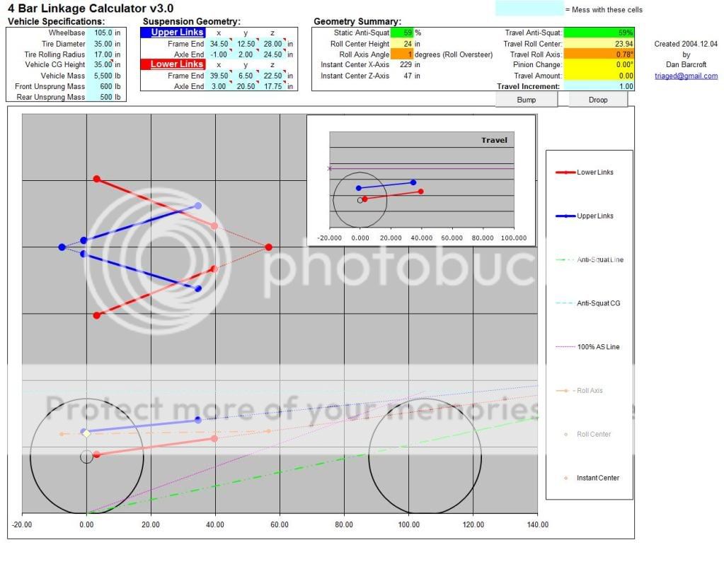
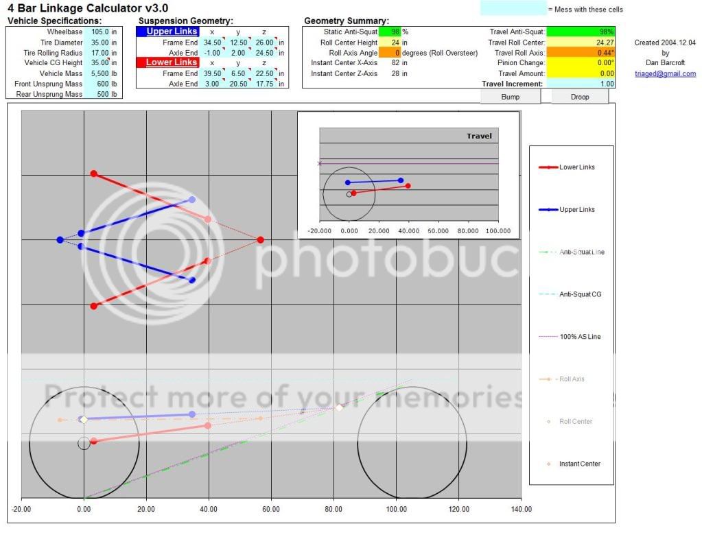
You know I actually got ahold of the guy who wrote that program, he layed it all out to me pretty well and after fiddling with it- Im going to make adjustable uppers. The axle end will have 2 holes 2" apart, the frame and will have 3 holes 2" apart. Here are the numbers it gives:
These numbers are @ 2" increments of the frame end, the axle end uppers are fixed @ their lower holes.

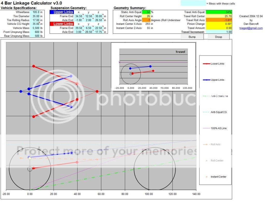
These numbers are @ 2" increments and the axle uppers are fixed in the upper holes, 2" higher than the previous 3 pics


I liked these numbers best I may start with these first
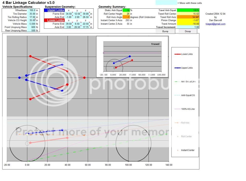
Here is the bump and droop pics

These numbers are @ 2" increments of the frame end, the axle end uppers are fixed @ their lower holes.
These numbers are @ 2" increments and the axle uppers are fixed in the upper holes, 2" higher than the previous 3 pics
I liked these numbers best I may start with these first
Here is the bump and droop pics
Last edited by Hardstripe; Jun 16, 2009 at 05:33 AM.
 Jun 16, 2009 | 11:54 AM
#25
Thread Starter
Registered User
Joined: Jun 2009
Posts: 124
Likes: 0
From: spokane, wa
Had the automotive engineer professor at the college look at my link calcs and pics of my fabrication, he says they look great- I asked him if my uppers axle side need to have the same width as my lowers frame side (Which someone gave me as advice)
He said its a good idea but I think with those joints you dont need to worry about binding anyways, go with what you got it looks great on the calculator.
See the red line on the last 3 pics? Its my forward thrust. Compare the end of my forward thrust in these 3 pics to the forward thrust in the rest of them. Basically you want your forward thrust to end on the front half of your vehicle, otherwise your thrust will move up, loading your tires and axle up under your vehicle. This is also where the upper link line and lower link line intersect, which goes back to how you see people recommending the links being horizontal to eachother for the lower end anti-squat. Now look at the top one of the last post. See how they are further from eachother on the frame end than the axle end? This makes the antisquat 20% but look at the instant center numbers and the lines of intersection of upper and lower arms. The arms are intersecting behind the vehicle and the instant center has negative values. The last setup has the thrust ending somewhere waaay off the graph, Has -1 degree understeer, and has a 59% anti-squat, I think it will make my rig the most capable- However I am still making the links adjustable so that when I get in and drive it I can fine tune my decision as I go.
I got the bolts in today, and I got some drill bits from a machine tool supply company- They didnt have an 18mm but I got a 23/32 and a 45/64 bit, they are as close to an 18mm as you can get. I am opting for the 45/64 first because its a little smaller than 18mm vs the 23/32 which is a little larger.
The decimals for each are:
45/64 = .7031
18mm = .7087
23/32 = .7188
Pretty damn close, Think it will work?
Ill take pics

 Aug 8, 2009 | 08:32 AM
#40

Registered User
Joined: Aug 2008
Posts: 264
Likes: 0
I also had hired help.. but she was an expert on SFA..lol... It was great she had the perfect size hands for greasing inside the knuckle.. If anyone needs help I have her contact info, and it will cost a package of double stuffed oreo's and some milk..lol


