
*Write Up* Installing the Yellow Box Speedo Calibrator
 Jun 5, 2010 | 12:20 PM
#1
Thread Starter
Registered User
Joined: Jan 2008
Posts: 11,338
Likes: 120
From: Austin, Texas
*Write Up* Installing the Yellow Box Speedo Calibrator
With the addition of over sized tires and lower gears in the differentials my speedometer had a 24% difference indicating 90MPH at an actual 70. Not acceptable.  Follow along as I install the Yellow Box Speedometer Calibrator into my 99 2.7L 5Speed Tacoma.
I checked the Yellow Box instructions and checked the wiring diagram on the NCTTORA site which led me to my conclusion of how to wire it up.
First, pull the wiring harness out from the trans/transfer case. There's 5 connectors (which I don't know the exact names of) that need to be disconnected and pushed towards the front of the vehicle.
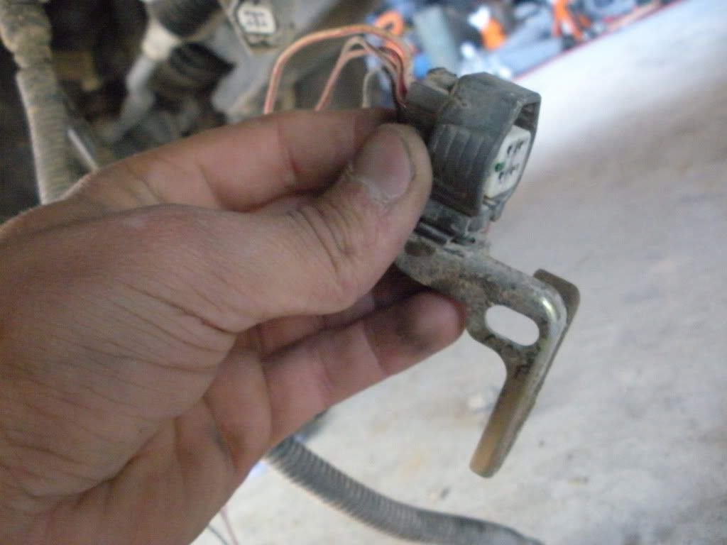
There is the VSS connector as well as the rear o2 sensor harness on the rear end of the transfercase

This is the rear o2 sensor plug, which bolts onto the Tcase somewhere in the above picture
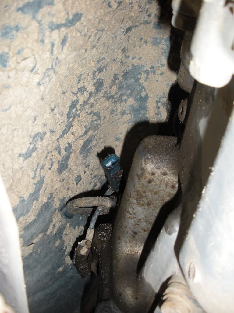
Moving forward there is the Tcase position sensor (passenger side) (I'm 99% sure that's what this one is called) I have small hands so it wasn't hard to get in there, but you might have to have your kid do it if you've got fat hands.
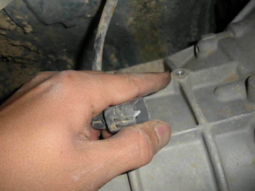
Then there is the front o2 sensor harness (passenger side, bolts into the hole I'm pointing at.)
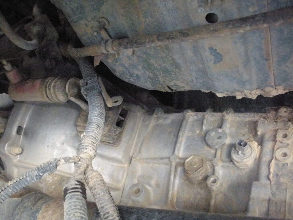
After that you can shove the harness over the top of the transmission to the drivers side and unplug the 5th and final plug of which I do not know the name
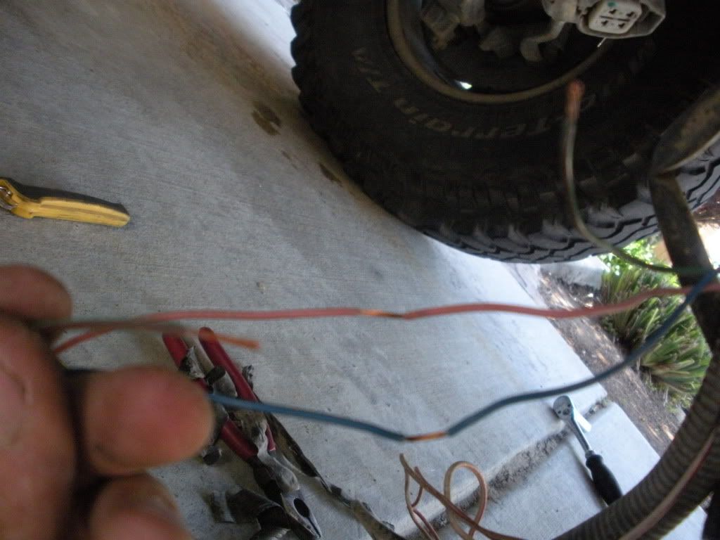
Once you have the harness in a good spot with enough room to work (and solder) you can pull the shielding and the electrical tape out of the way to reveal the 3 wires for the VSS. They are colored as follows : Red/black for POWER. Blue for GROUND and Green/Red for the SIGNAL WIRE.
For the power and ground wire you will want to strip (not cut) about a 1/2" of the shielding off of each. For the signal wire you will want to cut it and strip back a 1/2" of the shielding on each end. This picture may be a little hard to see but will give you an idea.
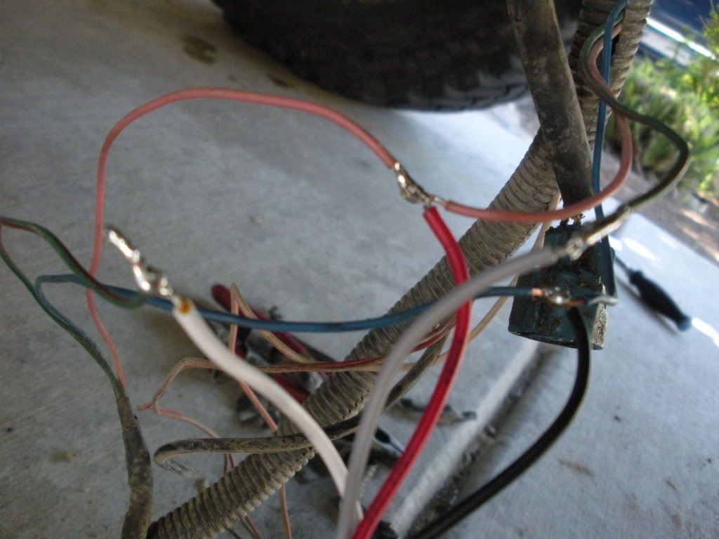
From there you will connect and solder the following wires.
Red/ black from the VSS gets connected to the Red wire from the yellow box.
Blue wire from VSS gets connected to the black wire from the yellow box.
The White wire from the Yellow Box gets connected to the VSS side of the Green wire.
The Gray wire from the yellow box gets connected to the ECM side of the Green wire.
Once you have them all connected solder them
Once your connections are soldered you can wrap them in electrical tape and shove the harness back into the plastic shielding. Reconnect all your sensors and run the wires where they need to be.
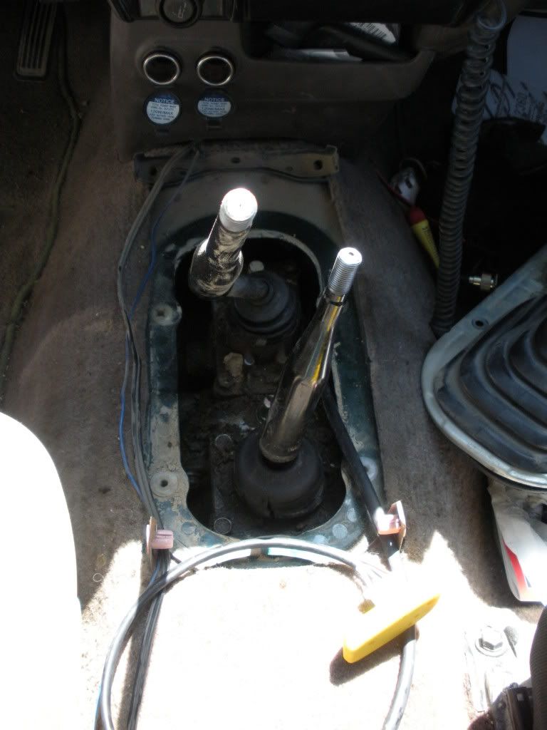
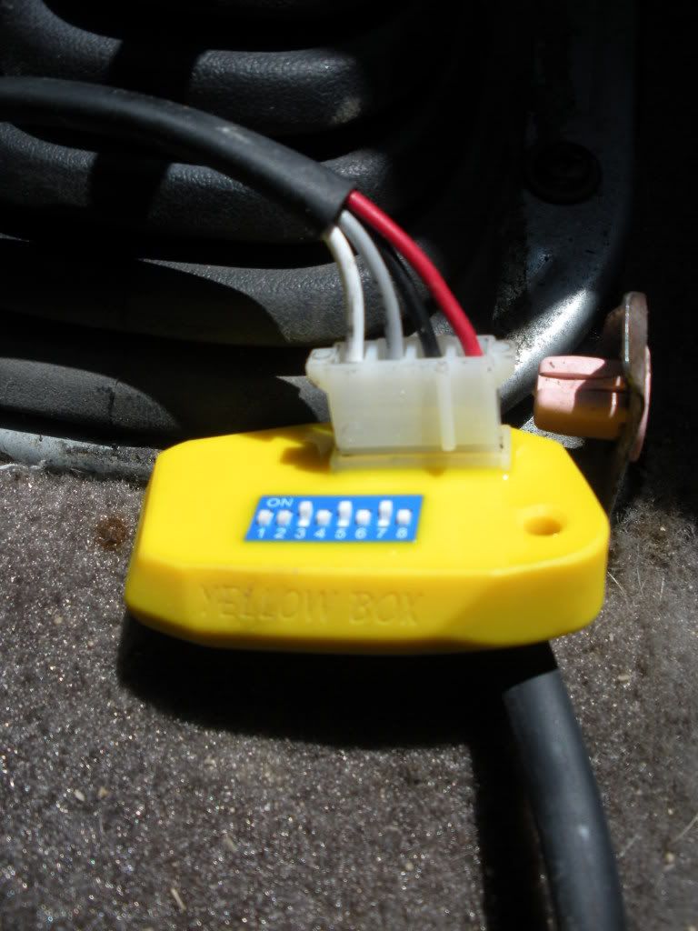
I chose to run the yellow box into the cab through the shifter boot hole. The actual yellow box unit will sit in the dead space under the center console
Kind of dirty
For size reference
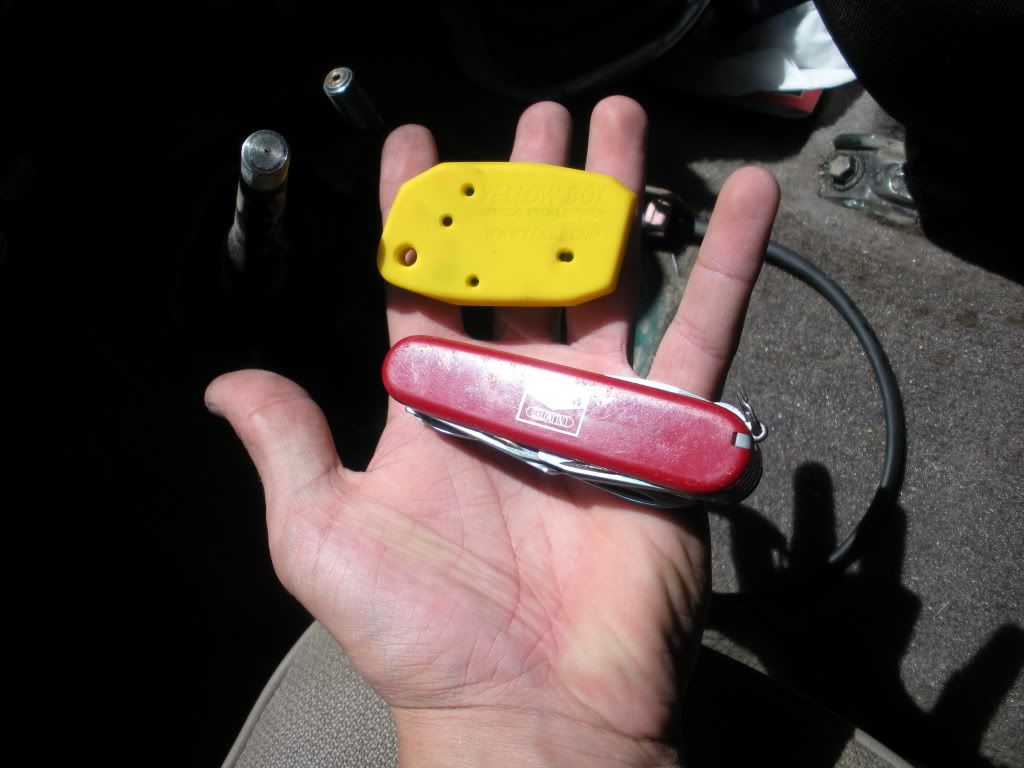
Here are the switches you flip to change the settings
That's about it. From there you will want to follow these instructions to figure your speedometers percentage of error and then use the correction table to get a rough estimate of where to start off for the calibration step.
My calculations gave me a 21% difference and I ended up having a 24/24.5% difference. So leave the yellow box in an easy to reach spot so you can take a test ride and get it where it needs to be. I think it is suggested that each time you change the settings make sure you power down the vehicle.
I took a run on the highway and had to stop and change it a few times in order to get it perfect.
After that you can reinstall your shifter trim or what have you and live a happy life knowing your speedometer is freakin dead nuts accurate

Follow along as I install the Yellow Box Speedometer Calibrator into my 99 2.7L 5Speed Tacoma. I checked the Yellow Box instructions and checked the wiring diagram on the NCTTORA site which led me to my conclusion of how to wire it up.
First, pull the wiring harness out from the trans/transfer case. There's 5 connectors (which I don't know the exact names of) that need to be disconnected and pushed towards the front of the vehicle.
There is the VSS connector as well as the rear o2 sensor harness on the rear end of the transfercase
This is the rear o2 sensor plug, which bolts onto the Tcase somewhere in the above picture
Moving forward there is the Tcase position sensor (passenger side) (I'm 99% sure that's what this one is called) I have small hands so it wasn't hard to get in there, but you might have to have your kid do it if you've got fat hands.
Then there is the front o2 sensor harness (passenger side, bolts into the hole I'm pointing at.)
After that you can shove the harness over the top of the transmission to the drivers side and unplug the 5th and final plug of which I do not know the name
Once you have the harness in a good spot with enough room to work (and solder) you can pull the shielding and the electrical tape out of the way to reveal the 3 wires for the VSS. They are colored as follows : Red/black for POWER. Blue for GROUND and Green/Red for the SIGNAL WIRE.
For the power and ground wire you will want to strip (not cut) about a 1/2" of the shielding off of each. For the signal wire you will want to cut it and strip back a 1/2" of the shielding on each end. This picture may be a little hard to see but will give you an idea.
From there you will connect and solder the following wires.
Red/ black from the VSS gets connected to the Red wire from the yellow box.
Blue wire from VSS gets connected to the black wire from the yellow box.
The White wire from the Yellow Box gets connected to the VSS side of the Green wire.
The Gray wire from the yellow box gets connected to the ECM side of the Green wire.
Once you have them all connected solder them
Once your connections are soldered you can wrap them in electrical tape and shove the harness back into the plastic shielding. Reconnect all your sensors and run the wires where they need to be.
I chose to run the yellow box into the cab through the shifter boot hole. The actual yellow box unit will sit in the dead space under the center console
Kind of dirty
For size reference
Here are the switches you flip to change the settings
That's about it. From there you will want to follow these instructions to figure your speedometers percentage of error and then use the correction table to get a rough estimate of where to start off for the calibration step.
My calculations gave me a 21% difference and I ended up having a 24/24.5% difference. So leave the yellow box in an easy to reach spot so you can take a test ride and get it where it needs to be. I think it is suggested that each time you change the settings make sure you power down the vehicle.
I took a run on the highway and had to stop and change it a few times in order to get it perfect.
After that you can reinstall your shifter trim or what have you and live a happy life knowing your speedometer is freakin dead nuts accurate


 Jun 6, 2010 | 03:47 PM
#5
Contributing Member
Joined: Sep 2002
Posts: 1,610
Likes: 0
From: Mission, British Columbia
Here is another product, does the same thing.
http://www.toyota120.com/forum/showthread.php?t=4821
It's easier to install it under the dash. Then you pick up the pulse signal to the speedometer, and just correct the speedometer & odometer.
For the abs & atrac it doesn't matter, it just compares the pulses from the transmission vs the wheel sensors etc.
Jun 6, 2010 | 05:02 PM
#7
Thread Starter
Registered User
Joined: Jan 2008
Posts: 11,338
Likes: 120
From: Austin, Texas
Here is another product, does the same thing.
http://www.toyota120.com/forum/showthread.php?t=4821
It's easier to install it under the dash. Then you pick up the pulse signal to the speedometer, and just correct the speedometer & odometer.
For the abs & atrac it doesn't matter, it just compares the pulses from the transmission vs the wheel sensors etc.
http://www.toyota120.com/forum/showthread.php?t=4821
It's easier to install it under the dash. Then you pick up the pulse signal to the speedometer, and just correct the speedometer & odometer.
For the abs & atrac it doesn't matter, it just compares the pulses from the transmission vs the wheel sensors etc.


Trending Topics
Jun 7, 2010 | 01:08 PM
#9
Thread Starter
Registered User
Joined: Jan 2008
Posts: 11,338
Likes: 120
From: Austin, Texas
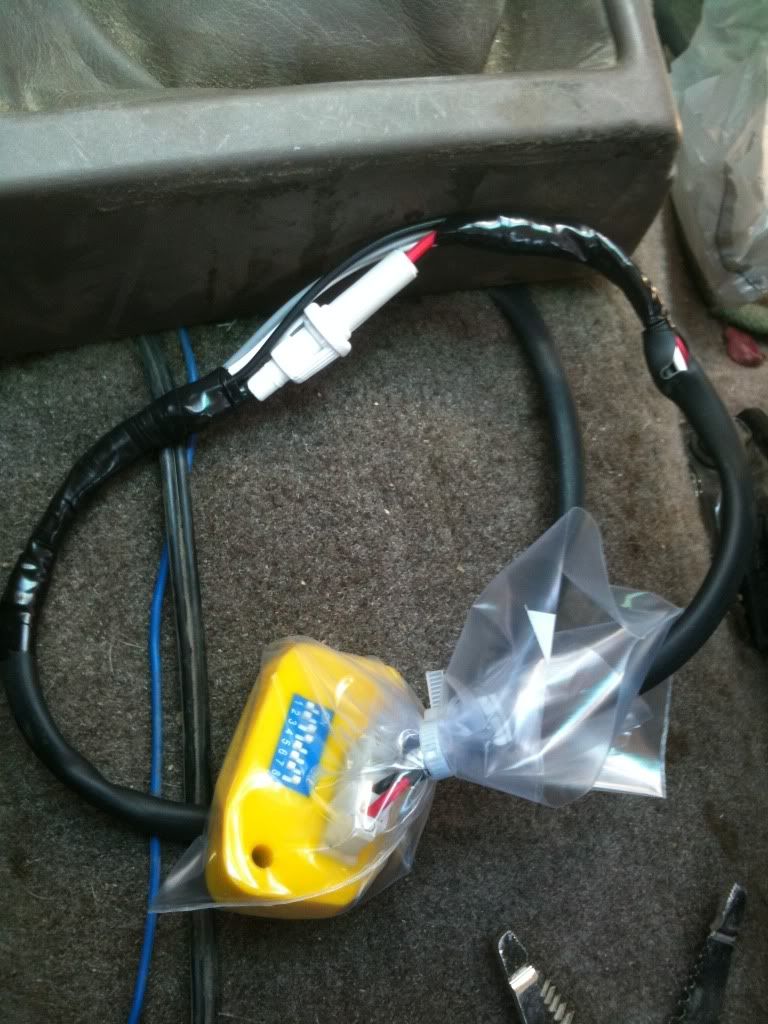
As suggested by a member of another forum, I added in a fuse. 2.5A
Also, while I was in there, per the instructions I wrapped the yellow box in some very high tech stuff in order to keep the dust out of yellow box.
Also, while I was in there, per the instructions I wrapped the yellow box in some very high tech stuff in order to keep the dust out of yellow box.
 Jun 7, 2010 | 06:16 PM
#11
Thread Starter
Registered User
Joined: Jan 2008
Posts: 11,338
Likes: 120
From: Austin, Texas
In one of my kitchen cabinets 
No ziplock bag here, only hamburger time brand baggies. They use a special polymer that induces an electro magnetic forcefield 10" around the yellow box. Get too close and your organs turn to mush. I had to wear a special suit that can only be made by top secret Russian scientists while handling the baggy.
No ziplock bag here, only hamburger time brand baggies. They use a special polymer that induces an electro magnetic forcefield 10" around the yellow box. Get too close and your organs turn to mush. I had to wear a special suit that can only be made by top secret Russian scientists while handling the baggy.
Jun 7, 2010 | 10:13 PM
#14
Not a bash at all, but I would be careful with the way that those wires are soldered. They look like they have been 'cold soldered'. A gold solder job should have a smoother end appearance where the wire bond is one solid blob (for lack of a better description), which is achieved by using the solder iron to heat the wire, and then applying the solder to the wire. Ideally, the iron itself never makes direct contact with the solder. The use of flux/resin aids in the bonding of the solder to the wires.
Jun 8, 2010 | 11:25 AM
#16
I only say just because that kind of connection is more brittle and more likely to fail from vibrations, etc over time, knowing how we drive our trucks ha. I've had to fix quite a few stereos, etc from loose wires from this very cause. But if you taped them well that will def. help
Oct 26, 2010 | 10:56 AM
#17
Thread Starter
Registered User
Joined: Jan 2008
Posts: 11,338
Likes: 120
From: Austin, Texas
The Yellow Box Speedometer Calibrator saves the day AGAIN!
My speedo was off again due to my jump from 33s to 35s.
My math gave me a 14% error but I ended up setting the box to 16%. Guess the stock speedo error is about 2%.
My speedo was off again due to my jump from 33s to 35s.
My math gave me a 14% error but I ended up setting the box to 16%. Guess the stock speedo error is about 2%.

Thread
Thread Starter
Forum
Replies
Last Post
rushw
General Electrical & Lighting Related Topics
4
Jul 18, 2015 01:46 PM
crashburnoveride
86-95 Trucks & 4Runners
1
Jul 10, 2015 06:39 AM


