When you click on links to various merchants on this site and make a purchase, this can result in this site earning a commission. Affiliate programs and affiliations include, but are not limited to, the eBay Partner Network.
And once again, my point has apparently gone completely over your head (or you've chosen to ignore it). Let's try this again...
Just because that O2 simulator's output satisfies the ECM, it does NOT mean that is what a real life, working downstream O2 sensor's output looks like.
That's hilarious!
I've proved you wrong about a dozen times now, and you keep changing your wording.
Now you are going to cling to "what a real life, working downstream O2 sensor's output looks like"??
The O2 simulators that I showed you generate a signal that the ECU is looking for. Engineers looked at the documentation for the ECU, saw what the ECU considers a good signal from the O2 sensor, and created an electronic device that simulates that ideal switching signal.
You keep saying that it's "not real life", yet this type of device is the only 100% guaranteed way to keep P0420 off in most OBDII vehicles. Spark plug non-foulers are a hack. Just like the resistor method. You have no clue how the resistor method even works, and as a consequence you can't grasp the extent of hack-iness that it is.
You keep changing the subject, but I'll give you an answer and an explanation! Maybe you'll even learn something!
Yes, in theory an O2 sensor with a removed or high flow or just old catalytic converter will "flatline" in the 0.9v range. This happens because the oxygen content in the exhaust gases exceeds what the O2 sensor can measure.
Learn something? LMAO, the only thing I've "learned" is that you have no clue as to what you're talking about. The fact you believe the rear O2 will "flatline" when the cat is missing is laughable, because it's so absolutely false. I've posted 2 articles, and a YouTube video about what the rear O2 reading will look like when the cat fails (or is removed), and not a single one of them say that the rear O2 will "flatline" like you insist that it does. "In theory" and in real life, common sense dictates that if the cat fails (or is removed) then the rear O2 will mimic a sine wave similar to that of the front O2, switching rapidly between lean/rich. Why? Because now the rear O2 is being exposed to the same untreated exhaust (and therefore, the same oxygen content) as the front O2 sensor. Marvelous concept, right?
And no, I'm not changing the subject on you. Unless I missed something, I have responded to all of your points and assertions that you have brought up. You, on the other hand, have resorted to misquoting me and picking and choosing small segments of my posts (and ignoring the rest), usually misconstruing what I say and taking things out of context for your own benefit.
Originally Posted by DailyDrive
Have you heard of another hack solution to the P0420 problem involving spark plug non-foulers and various spacers?
Quote:
The primary use of the spacer and or isolator is to take your O2 sensor out of the exhaust stream so that your O2 sensor senses less oxygen in the exhaust pipe.
Do you understand now? The spacer basically lowers the level of oxygen the sensor sees, so the varying levels of O2 in the exhaust gases come back down to the O2 sensor's measuring range, and it can again generate a sine wave, that crosses the very important 0.45v level, that the ECU is explicitly looking for.
If there is no switching signal coming from the O2, you'll get P0420. If it doesn't switch between 0.1v and 0.9v while crossing 0.45v, you'll get P0420. You keep denying this basic fact.
The problem with your assertion is that the rear O2 is already generating a rapid sine wave in this case (because the cat is assumed failed/missing, and you haven't yet added the spacers). Now, when you add in the spacers, what happens? Now you're shielding the rear O2 from the constant wide swings from rich/lean/rich/lean, and in effect you are smoothing out the voltage reading. It has nothing to do with "bringing oxygen levels back down to the O2 sensor's measuring range", because the O2 never "flatlined" in the first place when the cat failed/went missing.
I've proved you wrong about a dozen times now, and you keep changing your wording.
Now you are going to cling to "what a real life, working downstream O2 sensor's output looks like"??
The O2 simulators that I showed you generate a signal that the ECU is looking for. Engineers looked at the documentation for the ECU, saw what the ECU considers a good signal from the O2 sensor, and created an electronic device that simulates that ideal switching signal.
You keep saying that it's "not real life", yet this type of device is the only 100% guaranteed way to keep P0420 off in most OBDII vehicles. Spark plug non-foulers are a hack. Just like the resistor method. You have no clue how the resistor method even works, and as a consequence you can't grasp the extent of hack-iness that it is.
Proved me wrong? Changed my wording? LOL! Please point out where this has happened, I would love to see it. What I "grasp" is that after doing the resistor method, my CEL has gone off and has stayed that way (despite you insisting that it won't work). And in the end, that is what I'm trying to achieve: no more CEL.
It's quite provable what a properly functioning downstream O2 looks like, and it sure as hell doesn't look like the way you describe it. Again, watch the YouTube video I posted earlier if you want to see what it looks like. You'll also see what the rear O2 looks like when the cat has failed.
Oh, and I just took a closer look to the link you posted earlier. The fact that you posted a link to a "Run Your Car On Water!" website sheds a whole new light onto you. You're one of "those" people who thinks you can run your car on water, but that the "guvment" / oil companies / Chuck Norris / whoever is hiding this technology, aren't you?
What I "grasp" is that after doing the resistor method, my CEL has gone off and has stayed that way (despite you insisting that it won't work). And in the end, that is what I'm trying to achieve: no more CEL.
You still don't understand how the resistor method "works", even though you did it and think the problem is solved now.
I see by now that normal human logic doesn't work with you.
I'll pose one last question here, it's not for you, it's what is called a rhetorical question.
If the "resistor method" is a solution, why do O2 simulators that generate a switching O2 signal to fix P0420 is the preferred choice for non-cheapskates and professionals?
You still don't understand how the resistor method "works", even though you did it and think the problem is solved now.
I see by now that normal human logic doesn't work with you.
Normal human logic doesn't work with me? Wow, that's quite a claim coming from someone who has continously made false statements, has demonstrated a total lack of understanding for how the O2 sensors work, but then can provide nothing to back up these claims. Meanwhile, I provide credible 3rd party information that soundly refutes your claims, yet you just bury your head in the sand and and persist on claiming that you are correct and I am wrong. The fact is, you have been beaten so badly in this disagreement that you can't even provide a defense for any of your claims, or provide any credible sources to back them up. And I'm the one who "normal human logic" doesn't work on?
And yes, the fact that my CEL is out and stays out is what I am after, so yes, I consider my problem as fixed.
Originally Posted by DailyDrive
I'll pose one last question here, it's not for you, it's what is called a rhetorical question.
If the "resistor method" is a solution, why do O2 simulators that generate a switching O2 signal to fix P0420 is the preferred choice for non-cheapskates and professionals?
This is actually a legitimate question, I'm surprised you even had it in you. I have nothing against O2 simulators that generate their own signal entirely. The reason they are generaly prefered is because on most vehicles, they allow you to delete the rear O2 sensor all together (and even provide a false load for the O2 heater circuit to keep the ECU happy). This would be my prefered method, EXCEPT, my 4Runner is California Emissions spec'd. This means mine has an air-fuel sensor upstream, and not a normal O2. This wouldn't matter, except for the fact that the ECU periodically recalibrates the air-fuel sensor off of the downstream O2. So if I deleted the rear O2 entirely, the ECU would not be able to conduct it's recalibration of the air-fuel sensor, and will pop a CEL. By using the resistor/capcitor method, the rear O2 output is still kept in a range that keeps the ECU happy, and the ECU is still able to conduct the recalibration of the front air-fuel sensor using the downstream O2 sensor. This is the same reason URD sells an O2 sim that piggybacks off the rear O2 sensor.
So which one is it? Is it steady or switching? Both of those sentences came from you, and they contradict each other.
You were correct on the 2nd try though. The switching is absolutely mandatory. A proper O2 output will switch from between 0.1v and 0.9v around once every 3 seconds. If it's doesn't switch, or switches too fast, or switches too slow, it will throw a CEL.
This quote is correct, except you are interpriting it incorrectly.
The key word there is "average reading", not "levels off". Can you tell me what the average voltage reading of a sine wave that cycles between 0.1v and 0.9v? I'll give you a hint, it's right around 0.45v.
Again, the cyling is mandatory. If your rear O2 sensor outputs a steady signal of any voltage, it will throw a CEL.
I should say that I have no relationship with URD and never owned or disassembled their product. But the last time I looked at them, which was more than 5 years ago, they sold an "O2 simulator". They key word there is simulator. They advertised the product as a guaranteed method to get rid of P0420. That code can be thrown for many reasons, it could be a dead O2 sensor, a fouled up O2 sensor, a dead cat converter. The only way to fix all those problems is to completely simulate the rear O2 signal, which I assumed it did.
I also looked at various other aftermarket solutions, and they all worked on the same principle, by simulating a switching/cycling signal that would be sent to the ECU in a properly working system.
If the "new" URD "simulator" really does "condition" the signal from the rear O2 sensor, and depends on it to be there, and working, then it's a terrible solution, just like the resistor method.
For the reasons:
1.) A rear O2 sensor has a finite lifetime, it will become non-functional with age, and will not generate a switching signal. If the URD relies on the signal from the rear O2, then if your sensor goes out, you will end up with a CEL.
2.) The same for catalytic converter, it will degrade with age to the point that even a working O2 sensor won't output a signal, you will end up with a CEL.
3.) A rear O2 sensor's heater circuit has a finite lifetime, it will become non-functional with age, you will end up with a CEL. Just a different code, still a CEL.
A real O2 simulator is a very simple circuit. I've built one in a few hours with $1 of parts, and it has been working flawlessly for years.
Here is what it looks like:
It's incredibly simple, outputting a square wave signal that switches between 0.1v and 0.9 with a period of around 3 seconds. I will never have to replace my rear O2 sensor or the cat converters as it doesn't depend on them in any way anymore.
man I've been reading all over about using a single resistor (1MOm) and a Capacitor(1,2,4.7)uf whichever one will work, and am about to install it. But seeing your circuit and you saying its been keeping the CEL off continually makes me wanna just wire this circuitry you have. I drive a Lexus IS300 '01 so I thought I'd check some Toyota forums. I hope you can get back to me anyway possible. I'd appreciate a wiring diagram so much.
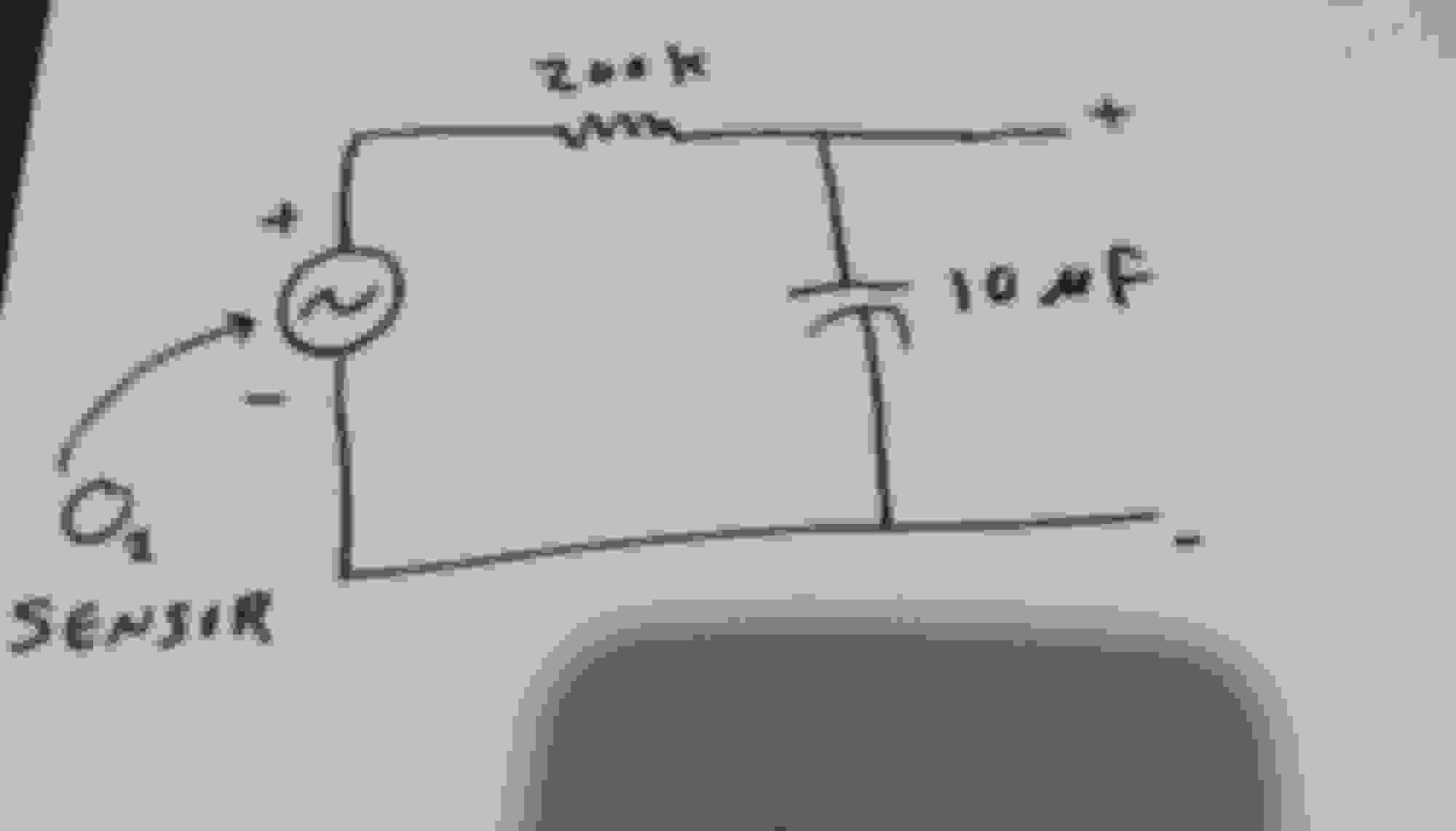
Simple passive low pass filter with break frequency of 0.5 Rad/s (200kohm, 10 uF) works great on my 2000 4runner (3.4L). First tried wb = 0.2 Rad/s, got rid of the P0420, but got a P0136. I've been running it like this for two years (~20000 miles) with no CEL.
Here's a matlab simulation of the filter along with actual O2 sensor data:
Last edited by leaver_red_jr; Mar 3, 2020 at 06:37 PM.
Hey thank you so kuchen for the reply! I don't really understand what you meant by any of that'll though. I'm not super tech savvy.. :/
but I do have a 1uf Cap and a 10k Ohm resistor that I've read elsewhere will work. I haven't installed the quite yet, but can.
just gotta pull up the seat and get under the carpet to the wires up close to the connector.
will that work you think?
that graph is pretty convincing..
Originally Posted by leaver_red_jr
Simple passive low pass filter with break frequency of 0.5 Rad/s (500kohm, 10 uF) works great on my 2000 4runner (3.4L). First tried wb = 0.2 Rad/s, got rid of the P0420, but got a P0136. I've been running it like this for two years (~20000 miles) with no CEL.
Here's a matlab simulation of the filter along with actual O2 sensor data:
Unfortunately, I think that the break frequency with that combination will be way too high to be effective. With a 10kohm resistor and 1uF cap, wb = 1/(10000*1e-6) = 100 Rad/sec. Basically, you wouldn't be altering the signal at all with that. Check out digikey. You can get the appropriate resistors and capacitors for a few dollars.
For capacitor, I used 10 uF, either digikey part# 490-12869-ND or 445-174239-1-ND. I don't remember which one I used, but either should work.
For resistor, I used 200k ohm, digikey # BC3256CT-ND.
You might want to get a few of each, and some of different values as well just to have on hand.
I put the resistor and capacitor right into the pigtail on the O2 sensor (solder and heat shrink).
Okay, we'll the wiring is definitely the sane as what I had planned on. I picked these up at radio shack so I guess I can do the same for these values parts too. I am just trying to find out why SO MANY other forums and videos on the YTube say to use the 1uf cap and 10K res?
Regarding the 10k/1uF, I don't know why it's suggested, but I know for a fact that it would not work on my truck. Seems like maybe a lot of people just like to parrot what the read somewhere without actually trying it or understanding what they're talking about.
Regarding the 10k/1uF, I don't know why it's suggested, but I know for a fact that it would not work on my truck. Seems like maybe a lot of people just like to parrot what the read somewhere without actually trying it or understanding what they're talking about.
man, so weird.. I'm still so confused as to what the original post I quoted was using. That has got multiple resistors, some smaller coin capacitors, all in a nice case, liquid taped up. Why, if it takes one simple Cap and Red did this guy build this complicated circuit?
also, I'd assume our ECUs are damn near the same since, we'll, Toyota. So I guess I'll try the 200k res and 10uf Cap and see how it fairs?? :-/
I just can't stand my CEL being on anymore. It makes me fearful some other issue will arise and I won't know. My original Cat ˟˟˟˟ on me 4 years ago, so I got an Eastern Catalytic knock off that did work, but isn't very effective "long term", obviously. So I'm not about to uninstall and replace my cats as its the entire header assembly, SO if this will rid me of the dreaded *P0420, I'll be the happiest Lexus owner this side the Mississippi!
In theory, this should work on your Lexus, but some fine tuning of the filter parameters might be required. Like I said in my original post, I first tried a combo of 500kouh/10uF because during simulation it looked good in terms of attenuating the "high" frequency part of the O2 signal. It did get rid of the P0420 code. However, the ECM on my 2000 4runner needs to see an O2 sensor voltage swing of 0.2V to 0.6V (or something like that) or it will through the P0136 code. As a result, I had to change the R and C values to accommodate this. Anyway, I hope it works for you.
From what I can tell, that other circuit (the one in the photos) acts as an actual simulator where it produces its own signal instead of just modifying the existing O2 sensor signal.
Oh I see. So basically to delete your cat completely in a modern ECU that requires an O2 sensor. That'd be what that's used for?
so if these values end up NOT WORKING, any suggestions of different Caps and Res combos I should use?
I would interpret it as a different way to basically get the same result. You could remove the cat entirely, and a passive filter would still work (assuming the correct parameters).
It would depend on what DTC(s) you get. For instance, if you try those values and still get P0420, maybe try to decrease the break frequency (use a larger C and/or R). If you get some other code, you'll need to figure out the cause, and adjust accordingly. It helps if you can log the data and run simulations so you can see what is going on. One other thing to consider is the impedence of the ECM. I measured mine to be only around 1Mohm, so I had to be careful about using too big of a resistor or O2 sensor voltage at the ECM would be too low (because of voltage divider effect).
I'd try the 200kohm/10uF, and go from there. These are both Toyotas from the same era, so I'd think things would be similar. If you still get the P0420, maybe try 200kohm/20uF or 500k/10uF and see if that kills it.
In theory, this should work on your Lexus, but some fine tuning of the filter parameters might be required. Like I said in my original post, I first tried a combo of 500kouh/10uF because during simulation it looked good in terms of attenuating the "high" frequency part of the O2 signal. It did get rid of the P0420 code. However, the ECM on my 2000 4runner needs to see an O2 sensor voltage swing of 0.2V to 0.6V (or something like that) or it will through the P0136 code. As a result, I had to change the R and C values to accommodate this. Anyway, I hope it works for you.
From what I can tell, that other circuit (the one in the photos) acts as an actual simulator where it produces its own signal instead of just modifying the existing O2 sensor signal.
Oh I see. So basically to delete your cat completely in a modern ECU that requires an O2 sensor. That'd be what that's used for?
so if these values end up NOT WORKING, any suggestions of different Caps and Res combos I should use?

 Aug 12, 2014 | 06:07 AM