
Installations instructions forTaurus Fan in Gen 3
 Apr 28, 2008 | 10:02 AM
#1


Installations instructions forTaurus Fan in Gen 3
This will be a multiple part installation of a Taurus 2 speed electric fan into a 3rd Gen 4Runner. The fan is from a 1995 Ford Taurus. The installed vehicle is a 1998 Toyota 4Runner. This was not as easy a mod as my install into my 1995 Gen 2. I still have a few things left to do and this is not going to be a quickie write up either so bare with me on this thread. If it interests you then I encourage you to subscribe as I will endeavor to update this as I progress and sort pics out to make sense of the install.
I encountered a few bumps and snafus during the installation. Some things worked while others did not so I had to do some recovery on occassion. But then what mod doesn't have it�s share of flubs, oops and head scratching
  along with some "engineering" changes during installation? I will try to relate those that occurred to me as we go to help save you the frustration I encountered.
I plan on posting a final complete version on the Tech Section. So enjoy and feel free to add comments, recommendations and changes I didn't think of, etc. I will attempt to incorporate those into the final write up
Part One
Taurus Electric fan on Gen 3 4Runner
NOTE:
Disclaimer: As with all modifications, this write up is for educational purposes only. Any use or application of this procedure is done so at the risk of the installer/owner. The author and YotaTech are not responsible for any modifications done to any vehicle using these or any other related procedures contained in this write up. Descriptions and photographs are the sole property and copyright of the author and may not be copied or distributed without written consent. Links to this article may be allowed but are protected by all US copyrights. Use of specific products along with any photographs of such items remains the copyrighted property of the copyright holder and is not an endorsement of any specific company or items.
Some hand tools you will need:
3/8 drive ratchet
3� extention
6� extention
8, 10, 12, 13 mm sockets and wrenches
Diagonal cutters
Wire strippers
Crimper
Jig saw
Drill with various size bits
Utility knife
Bucket
Funnel
Channel lock pliers
Assorted hand tools as required
Supplies:
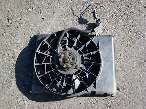
Taurus 2 speed electric fan
*Adjustable thermostat/controller
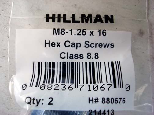
M8-1.25 x 12 or 16 metric bolts (4)
Washers (8-12) to fit the fan studs if you do not use the bolts
10 mm Bolts (3) for attaching the shroud to the fan
10 mm Washers (6) for attaching the shroud to the fan
Nylon wire ties � 6 & 10 inch
ABS type cement used for plumbing piping
(the black ABS cement may work better then the cream color General purpose ABS, PVC cement I used)
ABS cement cleaner
Split loom
Electrical tape
Loop connectors
Splice connectors 18 ga, 14-16 ga. 10-12 ga.
Blade connectors (12-10 ga., 14-16 ga. 18 ga.)
30 amp fuse
Wire of various sizes and colors:
12, 14 and 18 gauge
(I used wiring from an old harness so I could use similar colors for the wires from the switch, and relay controllers)
*I used two controllers, one for each speed and so one is thermo controlled the other is manual.
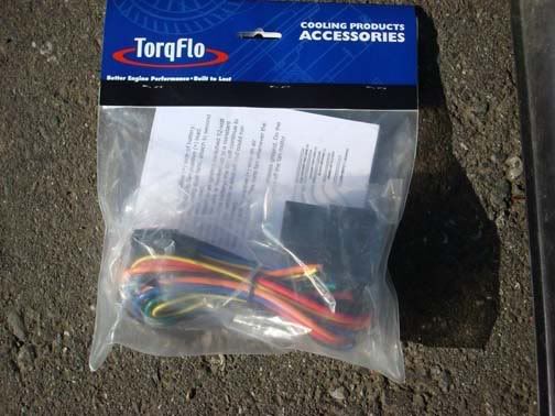
TorqFlo p/n 733647 Adjustable
TorqFlo p/n 733652 Single stage
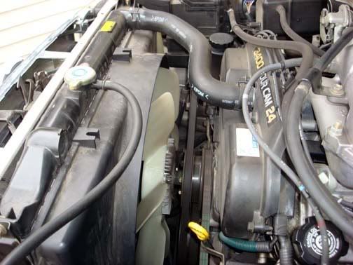
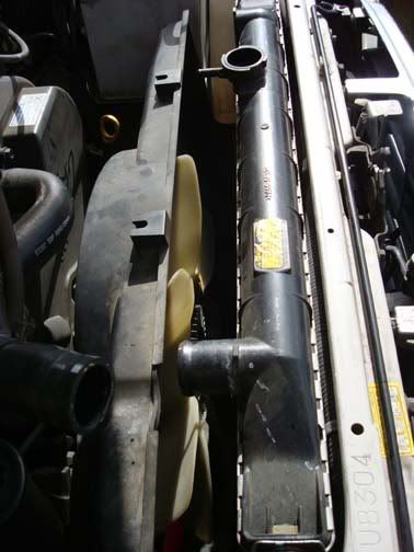
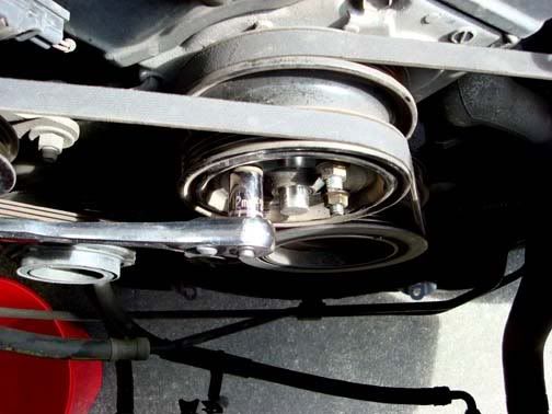
This is the engine bay before you begin.
Begin with dropping the skid plate. 5 � 12mm bolts
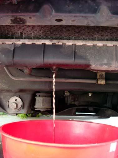
Using a suitable container, place it under the drain pet cock and open the valve. Remove the radiator cap and allow the system to drain.
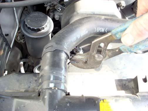
Remove the upper hose clamp.
Remove radiator overflow tube from the radiator cap. This is a simple clamp wire that can be easily removed with your fingers or use a small set of pliers.
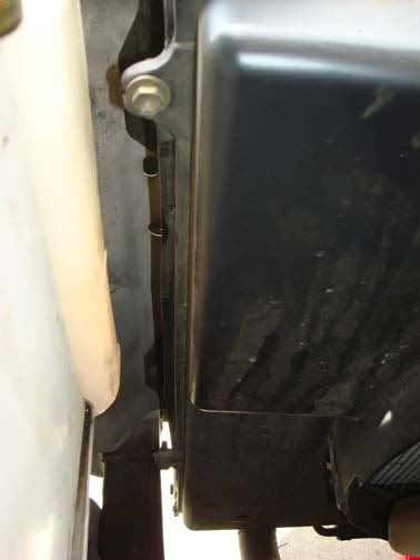
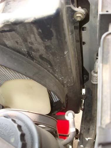
Remove the four (4) radiator 10 mm shroud bolts. Two on either side of the radiator.
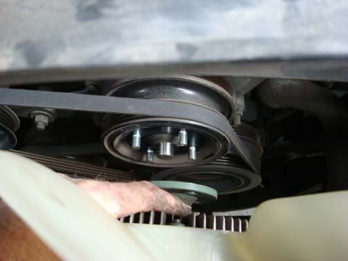
Push the loosened shroud towards the engine to allow room to get to the clutch fan.
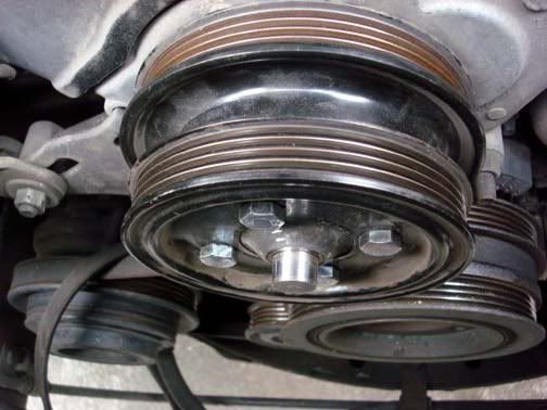
Remove the four (4) 12 mm clutch fan nuts that secure the clutch fan to the fan pully.

When the nuts have been removed, pull the fan clear of the engine compartment.
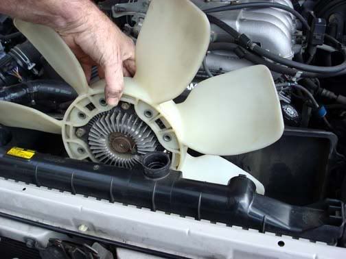
Remove the shroud.
NOTE: If your belts are in need of replacing, this would be a very good time to do so instead of installing the fan pulley nuts. You can wait and complete the radiator pulling steps before you complete the belt removal and subsequent installation. I mention this as you already have it torn apart. It will just save you some maintenance time later
If you intend on using the installed fan pulley threaded studs, install at least 3 flat washers on each stud then install the fan pulley nuts. And tighten.
Remove the lower radiator hose.
If you have not already removed the front grill, do so now.
Remove the four (4) radiator securing bolts. These are accessed from the front of the radiator.
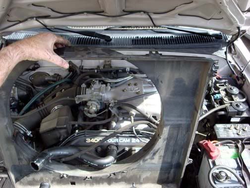
Pull the radiator directly upward and remove from the engine compartment
With the radiator removed you now have ample room to work on removal and replacement of belts.
NOTE: If you need or desire better clearance between the engine shaft of the fan pulley and the electric fan motor in the new radiator shroud, replacing the studs with metric bolts is optimal. I made the mistake of not installing washers on the fan pulley studs and when I tightened the nuts they seemed to be tight but were actually tightened on the end threads of the studs. When I discovered this error, I attempted to remove the studs and they pulled out.
Remove the studs with vise grip or channel lock pliers.

With the studs removed, install four (4) M8-1.25 12 or 16 mm bolts
If you desire to replace your drive belts do so at this time.
The next topic will be fitting the Taurus fan to our OEM Toyota fan shroud.
I encountered a few bumps and snafus during the installation. Some things worked while others did not so I had to do some recovery on occassion.
But then what mod doesn't have it�s share of flubs, oops and head scratching along with some "engineering" changes during installation? I will try to relate those that occurred to me as we go to help save you the frustration I encountered. I plan on posting a final complete version on the Tech Section. So enjoy and feel free to add comments, recommendations and changes I didn't think of, etc. I will attempt to incorporate those into the final write up
Part One
Taurus Electric fan on Gen 3 4Runner
NOTE:
Disclaimer: As with all modifications, this write up is for educational purposes only. Any use or application of this procedure is done so at the risk of the installer/owner. The author and YotaTech are not responsible for any modifications done to any vehicle using these or any other related procedures contained in this write up. Descriptions and photographs are the sole property and copyright of the author and may not be copied or distributed without written consent. Links to this article may be allowed but are protected by all US copyrights. Use of specific products along with any photographs of such items remains the copyrighted property of the copyright holder and is not an endorsement of any specific company or items.
Some hand tools you will need:
3/8 drive ratchet
3� extention
6� extention
8, 10, 12, 13 mm sockets and wrenches
Diagonal cutters
Wire strippers
Crimper
Jig saw
Drill with various size bits
Utility knife
Bucket
Funnel
Channel lock pliers
Assorted hand tools as required
Supplies:
Taurus 2 speed electric fan
*Adjustable thermostat/controller
M8-1.25 x 12 or 16 metric bolts (4)
Washers (8-12) to fit the fan studs if you do not use the bolts
10 mm Bolts (3) for attaching the shroud to the fan
10 mm Washers (6) for attaching the shroud to the fan
Nylon wire ties � 6 & 10 inch
ABS type cement used for plumbing piping
(the black ABS cement may work better then the cream color General purpose ABS, PVC cement I used)
ABS cement cleaner
Split loom
Electrical tape
Loop connectors
Splice connectors 18 ga, 14-16 ga. 10-12 ga.
Blade connectors (12-10 ga., 14-16 ga. 18 ga.)
30 amp fuse
Wire of various sizes and colors:
12, 14 and 18 gauge
(I used wiring from an old harness so I could use similar colors for the wires from the switch, and relay controllers)
*I used two controllers, one for each speed and so one is thermo controlled the other is manual.
TorqFlo p/n 733647 Adjustable
TorqFlo p/n 733652 Single stage
This is the engine bay before you begin.
Begin with dropping the skid plate. 5 � 12mm bolts
Using a suitable container, place it under the drain pet cock and open the valve. Remove the radiator cap and allow the system to drain.
Remove the upper hose clamp.
Remove radiator overflow tube from the radiator cap. This is a simple clamp wire that can be easily removed with your fingers or use a small set of pliers.
Remove the four (4) radiator 10 mm shroud bolts. Two on either side of the radiator.
Push the loosened shroud towards the engine to allow room to get to the clutch fan.
Remove the four (4) 12 mm clutch fan nuts that secure the clutch fan to the fan pully.
When the nuts have been removed, pull the fan clear of the engine compartment.
Remove the shroud.
NOTE: If your belts are in need of replacing, this would be a very good time to do so instead of installing the fan pulley nuts. You can wait and complete the radiator pulling steps before you complete the belt removal and subsequent installation. I mention this as you already have it torn apart. It will just save you some maintenance time later
If you intend on using the installed fan pulley threaded studs, install at least 3 flat washers on each stud then install the fan pulley nuts. And tighten.
Remove the lower radiator hose.
If you have not already removed the front grill, do so now.
Remove the four (4) radiator securing bolts. These are accessed from the front of the radiator.
Pull the radiator directly upward and remove from the engine compartment
With the radiator removed you now have ample room to work on removal and replacement of belts.
NOTE: If you need or desire better clearance between the engine shaft of the fan pulley and the electric fan motor in the new radiator shroud, replacing the studs with metric bolts is optimal. I made the mistake of not installing washers on the fan pulley studs and when I tightened the nuts they seemed to be tight but were actually tightened on the end threads of the studs. When I discovered this error, I attempted to remove the studs and they pulled out.
Remove the studs with vise grip or channel lock pliers.
With the studs removed, install four (4) M8-1.25 12 or 16 mm bolts
If you desire to replace your drive belts do so at this time.
The next topic will be fitting the Taurus fan to our OEM Toyota fan shroud.
Apr 29, 2008 | 05:49 AM
#2
Part 2
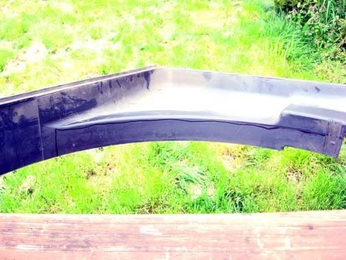
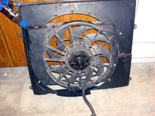
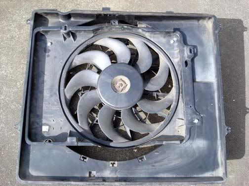
In this section we will be gin the installation of the Taurus fan into the OEM 4Runner shroud. Unlike the installation into a Gen 2 4Runner, the OEM shroud for the 3.4 V6 is considerably larger and as such is not as easy a direct bolt in. As can be seen in the picture, the OEM shroud is much larger and there for to use the Taurus fan some cutting will need to be done in order to utilize the radiator coverage that the OEM shroud affords.
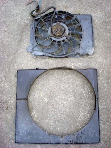
Begin by placing the fan on the ground and lay the shroud over it to begin to see what the optimum center is located.
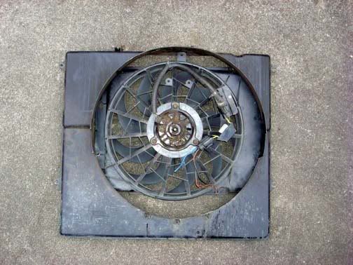
I attempted to place the fan so that it can utilize the contour of the shroud while still remaining flat or flush with the radiator fins. This did prove to be a bit of a challenge. The fan needed to be some what against the shroud for mounting as well as to provide for maximum air draw from all parts of the radiator but also not to be too far back so as to impinge one the fan pulley once installed.
Initially I attempted to mount the fan totally using � 20 bolts and washers but this proved to not be a desirable solution so cutting would not be involved.
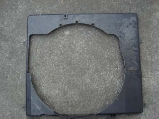
Note: The next portion of the cutting of the OEM shroud is not mandatory but can be accomplished if desired. At first I thought I would need to remove a portion of the OEM shroud rear extended edge, but after final fitment and gluing I discovered that removal of this material was not needed. If you desire to do so then I provide the pictures for your evaluation.

Mark and remove the following portions of the shroud:
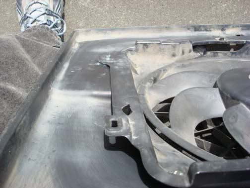
Both lower corners will require that you mark the location of the Fan in the shroud in order to allow the fan to “fit” into the lower portion of the shroud. When you mark these for cutting be sure to remember that you do not need to remove so much that the flange on the taurus fan is still inside the OEM shroud. This will allow the fan to fit more flush against the radiator due to the change in levels of the OEM shroud.
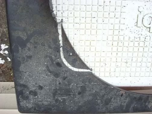
After removal of the corner material check the fit again to ensure the fan will be nearly flush in the shroud.
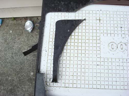
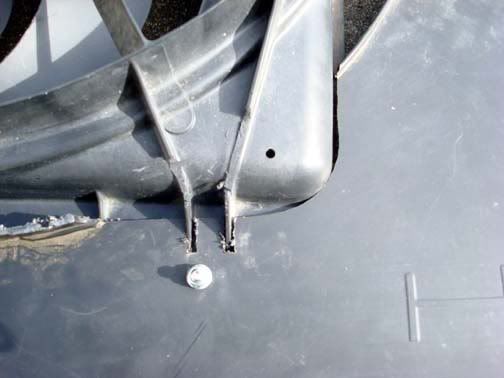
You will notice that you will need to cut two notches in the lower right corner to accommodate the fan support braces moulded into the Taurus shroud. Mark the location and use the jig saw to cut the notches.
When you are satisfied with the location of the fan, drill a hole at each corner (3 total) to provide for attachment of the fan and OEM shroud.
Using a large clamp, position the fan in the lower large cutout to check for fitment and to see if it is flush.
This is in preparation for gluing the larger cutout in the OEM shroud to the Taurus fan. There are some other options but I felt that gluing this corner was the best method of securing this large corner.
Check your position and fitment.

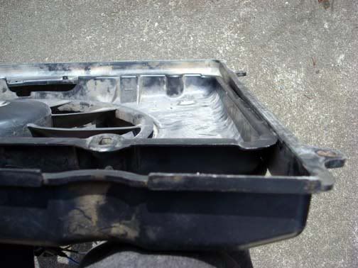
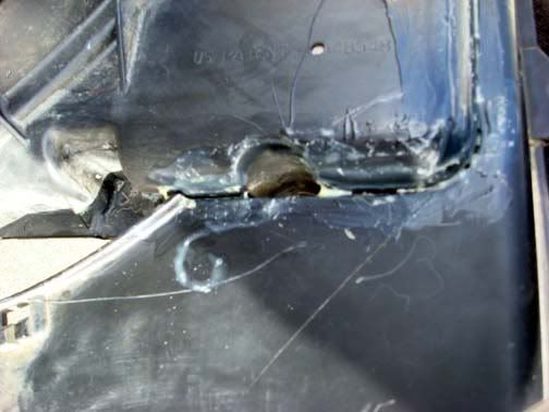
Glue the large cutout in place. I tried several different types of glue. First I tried an epoxy made for plastic but after setting, the glue did not adhere very well to the fan and shroud. When the fan was set down on the ground, the shock of contact with the ground, minor as it was caused the epoxy to release. Next was ABS plastic pipe cement. There are several types available. I chose the General cement. It comes in a red can and is cream colored. Used with the recommended plastic cleaner which is in a yellow can. This can be obtained in most any hardware store such as Home Depot or Lowes. Another option is the standard ABS cement that is black in color. I was not sure when I looked at these cements as I was not sure if the standard ABS cement would be too hot for the plastic. It is worth investigating as it may be a better solution and it would match the color of our fan and shroud.
Liberally use the cement along the seams. There will be a slight gap along this cutout and the fan itself so use enough to provide for a fill. Allow this to remain undisturbed for at least 12 hours.
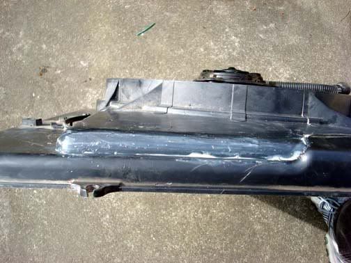
Once the glue has cured, you will have your completed fan ready for installation into the engine bay.
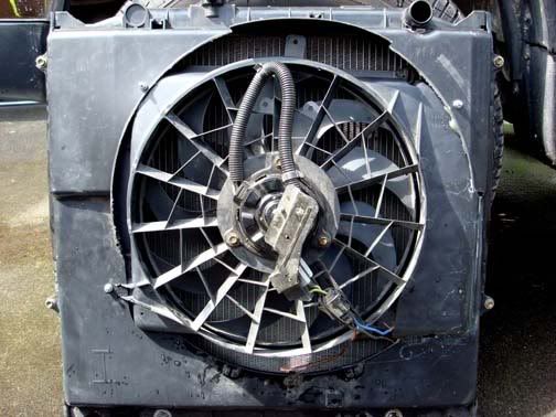
One thing I noted during fitup in the engine bay was that I was in need of a bit more clearance between the fan motor housing and the fan pulley. I obtained the needed clearance by placing 2-3 washers between the OEM shroud and the fan at the two bolts on the left side of the fan. This pulled the fan forward slightly into the shroud towards the radiator providing additional clearance of about 1/4". Check your fitment and determine if you need to add these extra washers.
Next, Installation in the Engine Bay
In this section we will be gin the installation of the Taurus fan into the OEM 4Runner shroud. Unlike the installation into a Gen 2 4Runner, the OEM shroud for the 3.4 V6 is considerably larger and as such is not as easy a direct bolt in. As can be seen in the picture, the OEM shroud is much larger and there for to use the Taurus fan some cutting will need to be done in order to utilize the radiator coverage that the OEM shroud affords.
Begin by placing the fan on the ground and lay the shroud over it to begin to see what the optimum center is located.
I attempted to place the fan so that it can utilize the contour of the shroud while still remaining flat or flush with the radiator fins. This did prove to be a bit of a challenge. The fan needed to be some what against the shroud for mounting as well as to provide for maximum air draw from all parts of the radiator but also not to be too far back so as to impinge one the fan pulley once installed.
Initially I attempted to mount the fan totally using � 20 bolts and washers but this proved to not be a desirable solution so cutting would not be involved.
Note: The next portion of the cutting of the OEM shroud is not mandatory but can be accomplished if desired. At first I thought I would need to remove a portion of the OEM shroud rear extended edge, but after final fitment and gluing I discovered that removal of this material was not needed. If you desire to do so then I provide the pictures for your evaluation.
Mark and remove the following portions of the shroud:
Both lower corners will require that you mark the location of the Fan in the shroud in order to allow the fan to “fit” into the lower portion of the shroud. When you mark these for cutting be sure to remember that you do not need to remove so much that the flange on the taurus fan is still inside the OEM shroud. This will allow the fan to fit more flush against the radiator due to the change in levels of the OEM shroud.
After removal of the corner material check the fit again to ensure the fan will be nearly flush in the shroud.
You will notice that you will need to cut two notches in the lower right corner to accommodate the fan support braces moulded into the Taurus shroud. Mark the location and use the jig saw to cut the notches.
When you are satisfied with the location of the fan, drill a hole at each corner (3 total) to provide for attachment of the fan and OEM shroud.
Using a large clamp, position the fan in the lower large cutout to check for fitment and to see if it is flush.
This is in preparation for gluing the larger cutout in the OEM shroud to the Taurus fan. There are some other options but I felt that gluing this corner was the best method of securing this large corner.
Check your position and fitment.
Glue the large cutout in place. I tried several different types of glue. First I tried an epoxy made for plastic but after setting, the glue did not adhere very well to the fan and shroud. When the fan was set down on the ground, the shock of contact with the ground, minor as it was caused the epoxy to release. Next was ABS plastic pipe cement. There are several types available. I chose the General cement. It comes in a red can and is cream colored. Used with the recommended plastic cleaner which is in a yellow can. This can be obtained in most any hardware store such as Home Depot or Lowes. Another option is the standard ABS cement that is black in color. I was not sure when I looked at these cements as I was not sure if the standard ABS cement would be too hot for the plastic. It is worth investigating as it may be a better solution and it would match the color of our fan and shroud.
Liberally use the cement along the seams. There will be a slight gap along this cutout and the fan itself so use enough to provide for a fill. Allow this to remain undisturbed for at least 12 hours.
Once the glue has cured, you will have your completed fan ready for installation into the engine bay.
One thing I noted during fitup in the engine bay was that I was in need of a bit more clearance between the fan motor housing and the fan pulley. I obtained the needed clearance by placing 2-3 washers between the OEM shroud and the fan at the two bolts on the left side of the fan. This pulled the fan forward slightly into the shroud towards the radiator providing additional clearance of about 1/4". Check your fitment and determine if you need to add these extra washers.
Next, Installation in the Engine Bay
Last edited by Ritzy4Runner; Apr 30, 2008 at 04:41 AM.
Apr 29, 2008 | 08:18 AM
#4
the write up you will find that there are 3 bolts and washers on the 3 of the 4 corners the only one without is the corner where you had to glue the large cutout.that are holding the fan in the shroud "When you are satisfied with the location of the fan, drill a hole at each corner (3 total) to provide for attachment of the fan and OEM shroud." Yeah I know that adhesive would not be enough unless it was a complete weld/melting of the plastic such as a chemical bonding/moulding of the two pieces. Hey it is easy to miss with all the write up
 Apr 29, 2008 | 09:33 AM
#5
Contributing Member
Joined: Mar 2003
Posts: 11,334
Likes: 0
From: COTKU,Ontario,Canada
In part 1 you talked about installing (re-installing?) the fan pulley nuts if you were keeping the studs. I would have suggested replacing them with nylok type nuts. In fact FWIW I would have used nyloks for all nut fastners for the extra bit of security. Additionally I would have mentioned using anti-seize or loc-tite thread locker on all fittings. just my 0.02...
Great write-up so far... I was going to do this mod on my 2gen but somebody chucked out my taurus fan before I could get around to installing it...
Great write-up so far... I was going to do this mod on my 2gen but somebody chucked out my taurus fan before I could get around to installing it...
Apr 29, 2008 | 11:00 AM
#6
In part 1 you talked about installing (re-installing?) the fan pulley nuts if you were keeping the studs. I would have suggested replacing them with nylok type nuts. In fact FWIW I would have used nyloks for all nut fastners for the extra bit of security. Additionally I would have mentioned using anti-seize or loc-tite thread locker on all fittings. just my 0.02...
Great write-up so far... I was going to do this mod on my 2gen but somebody chucked out my taurus fan before I could get around to installing it...
Great write-up so far... I was going to do this mod on my 2gen but somebody chucked out my taurus fan before I could get around to installing it...
Apr 29, 2008 | 11:19 AM
#7
Contributing Member
Joined: Mar 2003
Posts: 11,334
Likes: 0
From: COTKU,Ontario,Canada
You can get them up here but they are not that common. I found some at a commercial fastning supplier. you might try a Co. called Brafasco I think they have a web site and do net orders...
Trending Topics
Apr 30, 2008 | 06:21 AM
#8
Part 3
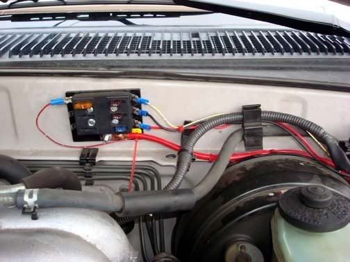
Begin by prepping the installation area. I would like to recommend that you consider adding the Auxillary Fuse panel if you have not already installed it. There are several excellent articles on installation. I installed one in my engine compartment on the firewall and it is excellent for providing you with the contact points for power for running all sorts of various accessories. If you intend on doing any accessory lighting such as fog or driving lights, additional 12vdc outlets or supplying power for a power amp for your sound system, I can not begin to recommend this mod enough. All power needs for this mod are supplied from my Aux Fuse panel. My connections refer to this for hookup. Here is where mine is installed. This will provide all the power needs for the fan and relays.
One thing that will aid in the installation of the wiring, installation of the relays and hook up of the fan itself is to remove the air box.
This next step is for 96-98 4Runners with stock air intakes. Remove the connector from the MAF sensor.
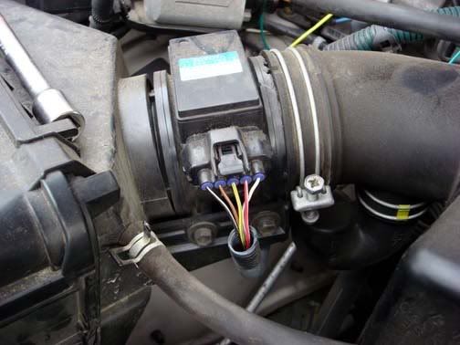
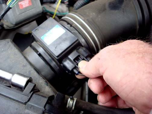
Grasp the top of the connector and squeeze the tab. Pull the connector out of the MAF.
Remove the two bolts at the base of the MAF.

Remove 3 bolts holding the air box in place. The one located on the radiator cross support piece will be completely removed while the ones located on the fender, one front and one rear of the air box are captive bolts. Just loosen them completely.
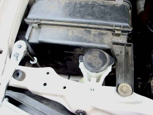
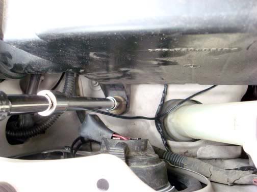
Pull the MAF from the rear of the air box.

Pull the air box out of the fender towards the engine and when free of the fender opening, pull the air box out of the engine bay and set aside.

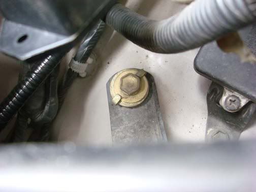
On the right side fender you will note several factory accessory attachment points.

I chose these two with OEM installed nuts as the attachment points for the relays. These provided two major advantages.
1) Ready made solid attachment points requiring no drilling.
2) Easy access to the temperature adjusting set screw on the LO speed relay.
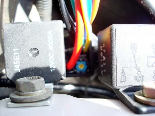
Using 10 mm bolts, attach the relays to the fender well.
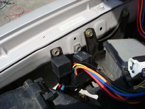
I would recommend now that you remove the bolts that secure several components along the fender towards the firewall to aid in routing the wires necessary to power the fans and relays.
The Taurus fan I obtained was from a 1995 sedan with the 3.8 V6. While it may not be necessary, I obtained the entire cable for the fan. This included a rather unusual looking connection that the fan plugged into. I was never able to find out just what this connection does but I did discover that 1995 was the only year they installed this “control relay/fuse” connector. The Ford dealer could not explain its purpose and the electrical diagrams for the car did not show them in the circuit, but the part was over $100, I figured, some engineer thought it was a good idea so I kept mine and installed it.
There are three (3) wires.
Blue – HI speed
Brown/Yellow – LO speed
Black – Ground for both fan speeds.
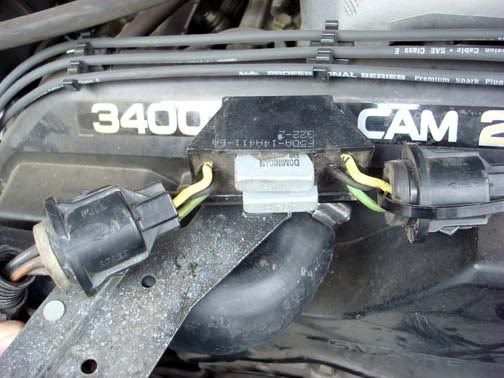
When I removed my fan from the donor vehicle, the Brown/yellow wires actually were two smaller wires spliced into a single larger gauge wire coming out of the connector. When I spliced the LO speed control wire from the control relay, I spliced in both the wires instead of cutting them near the factory splice at the larger gauge wire. This facilitated not having to either add wire to the relay wires or cut the other relay connections shorter. It just gave me more wire to work with.
The colors change coming out of the connectors to the box, then change back leaving the other side connector.

If you use this fan from a different year Taurus/Sable or Lincoln this connection may not be there. So to simplify the installation I just mounted the fan relay box to the radiator shroud.
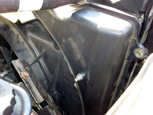
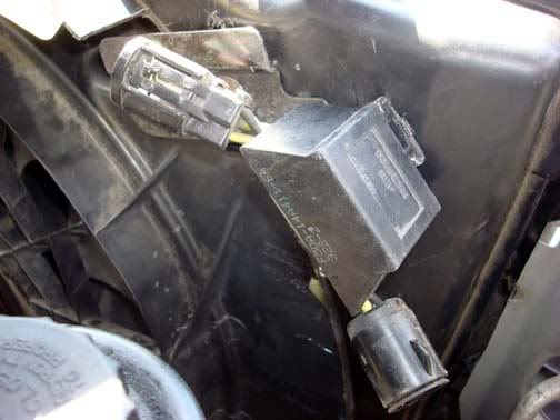
It required drilling a hole in the shroud near the top. I had removed some of the shroud trailing edge material during my shroud modification so it made the placement very easy. If you do not remove this edge material you may need to modify where you place the fan box. My location followed the contour of the fan and direction of the mounting plate and wires. This also provided for easy attachment/splicing of the wires from the fan to the control relays.
Fan control
While it is not necessary to provide for dual control of this 2 speed fan, it is very practical. Any two or three position switch can provide you with the degree of control you desire. I chose to use a three position switch, ON-OFF-ON rocker switch. Having the two ON positions allow for control of the two speeds.
LO is wired in so that the thermostat controlled relay will operate the fan slow speed as required by engine temperature demands. HI is a full manual control which cuts the power to the slow speed of the fan while energizing the high speed setting independently. Selecting the OFF position removes power from both settings which can be useful in water crossings preventing water from splashing into the fan blades while they are moving which has been known to damage the plastic fan blades. Just another added bonus of this installation.
My choice of switch was a rear heater fan speed selector switch from the console of a 4runner. Choosing this switch allowed me the ease of installation into my drivers dash and it is already marked as a fan! While I did have to modify the switch for proper operation, it is a very simple switch mod that requires minimal soldering skills. If you chose this switch for your fan control, I would recommend that you also get not just the switch, but get the connector from the console that it plugs into. You will want to be able to disconnect the switch from the cabling if you need to remove the lower dash panel.
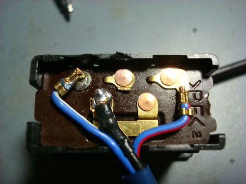
This is the switch as Toyota configured it for use in the rear heater speed select.

You will note the three (3) wires coming from the switch.
Blue/white – LO speed select (left side)
Black – common for both speeds (center)
Blue/red – HI speed (right side)
NOTE: I initially moved the blue/white from the common bus bar at the center/bottom of the switch to the upper left corner (see diagram) but found out the way the switch is internally set up this would not work correctly for our application. Eventually I had to move the black center contact to the lower bus bar. This would later be used as 12vdc input to the switch. While this made for easier identification of wiring, it involved a second wire removal and solder. If you don’t mind doing this, then you can do as I did. In hind sight, I would have left the wires configured and move only the black from center top to let top leaving the bus bar with the blue/white wire. You just have to remember the colors of the wires as you go to make this simpler.
Using a small pair of needle nose pliers, grasp the Blue/white wire near the contact. Move this up and down until the contact breaks free. Using some solder and flux, clean and solder the separated contact to the upper most left contact.
Check continuity using a multi-meter in both LO and HI switch positions and no continuity when the switch is in OFF.
Route the switch wire through the lower dash panel opening provided for a Toyota switch and connector.

Using a pull wire, push the pull wire from the firewall side of the engine on the drivers side into the passenger compartment.
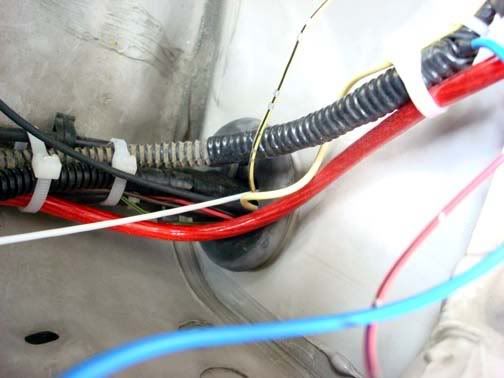
Attach the wires from the switch to the end of the pull wire with tape.
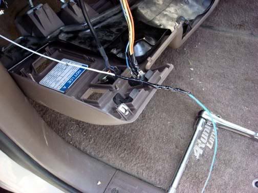
Pull the wires through the firewall into the engine compartment.

Now we are ready to begin wiring up the fan and switch control to the relays.
Next: Wiring up the system.
Begin by prepping the installation area. I would like to recommend that you consider adding the Auxillary Fuse panel if you have not already installed it. There are several excellent articles on installation. I installed one in my engine compartment on the firewall and it is excellent for providing you with the contact points for power for running all sorts of various accessories. If you intend on doing any accessory lighting such as fog or driving lights, additional 12vdc outlets or supplying power for a power amp for your sound system, I can not begin to recommend this mod enough. All power needs for this mod are supplied from my Aux Fuse panel. My connections refer to this for hookup. Here is where mine is installed. This will provide all the power needs for the fan and relays.
One thing that will aid in the installation of the wiring, installation of the relays and hook up of the fan itself is to remove the air box.
This next step is for 96-98 4Runners with stock air intakes. Remove the connector from the MAF sensor.
Grasp the top of the connector and squeeze the tab. Pull the connector out of the MAF.
Remove the two bolts at the base of the MAF.
Remove 3 bolts holding the air box in place. The one located on the radiator cross support piece will be completely removed while the ones located on the fender, one front and one rear of the air box are captive bolts. Just loosen them completely.
Pull the MAF from the rear of the air box.
Pull the air box out of the fender towards the engine and when free of the fender opening, pull the air box out of the engine bay and set aside.
On the right side fender you will note several factory accessory attachment points.
I chose these two with OEM installed nuts as the attachment points for the relays. These provided two major advantages.
1) Ready made solid attachment points requiring no drilling.
2) Easy access to the temperature adjusting set screw on the LO speed relay.
Using 10 mm bolts, attach the relays to the fender well.
I would recommend now that you remove the bolts that secure several components along the fender towards the firewall to aid in routing the wires necessary to power the fans and relays.
The Taurus fan I obtained was from a 1995 sedan with the 3.8 V6. While it may not be necessary, I obtained the entire cable for the fan. This included a rather unusual looking connection that the fan plugged into. I was never able to find out just what this connection does but I did discover that 1995 was the only year they installed this “control relay/fuse” connector. The Ford dealer could not explain its purpose and the electrical diagrams for the car did not show them in the circuit, but the part was over $100, I figured, some engineer thought it was a good idea so I kept mine and installed it.
There are three (3) wires.
Blue – HI speed
Brown/Yellow – LO speed
Black – Ground for both fan speeds.
When I removed my fan from the donor vehicle, the Brown/yellow wires actually were two smaller wires spliced into a single larger gauge wire coming out of the connector. When I spliced the LO speed control wire from the control relay, I spliced in both the wires instead of cutting them near the factory splice at the larger gauge wire. This facilitated not having to either add wire to the relay wires or cut the other relay connections shorter. It just gave me more wire to work with.
The colors change coming out of the connectors to the box, then change back leaving the other side connector.
If you use this fan from a different year Taurus/Sable or Lincoln this connection may not be there. So to simplify the installation I just mounted the fan relay box to the radiator shroud.
It required drilling a hole in the shroud near the top. I had removed some of the shroud trailing edge material during my shroud modification so it made the placement very easy. If you do not remove this edge material you may need to modify where you place the fan box. My location followed the contour of the fan and direction of the mounting plate and wires. This also provided for easy attachment/splicing of the wires from the fan to the control relays.
Fan control
While it is not necessary to provide for dual control of this 2 speed fan, it is very practical. Any two or three position switch can provide you with the degree of control you desire. I chose to use a three position switch, ON-OFF-ON rocker switch. Having the two ON positions allow for control of the two speeds.
LO is wired in so that the thermostat controlled relay will operate the fan slow speed as required by engine temperature demands. HI is a full manual control which cuts the power to the slow speed of the fan while energizing the high speed setting independently. Selecting the OFF position removes power from both settings which can be useful in water crossings preventing water from splashing into the fan blades while they are moving which has been known to damage the plastic fan blades. Just another added bonus of this installation.
My choice of switch was a rear heater fan speed selector switch from the console of a 4runner. Choosing this switch allowed me the ease of installation into my drivers dash and it is already marked as a fan! While I did have to modify the switch for proper operation, it is a very simple switch mod that requires minimal soldering skills. If you chose this switch for your fan control, I would recommend that you also get not just the switch, but get the connector from the console that it plugs into. You will want to be able to disconnect the switch from the cabling if you need to remove the lower dash panel.
This is the switch as Toyota configured it for use in the rear heater speed select.
You will note the three (3) wires coming from the switch.
Blue/white – LO speed select (left side)
Black – common for both speeds (center)
Blue/red – HI speed (right side)
NOTE: I initially moved the blue/white from the common bus bar at the center/bottom of the switch to the upper left corner (see diagram) but found out the way the switch is internally set up this would not work correctly for our application. Eventually I had to move the black center contact to the lower bus bar. This would later be used as 12vdc input to the switch. While this made for easier identification of wiring, it involved a second wire removal and solder. If you don’t mind doing this, then you can do as I did. In hind sight, I would have left the wires configured and move only the black from center top to let top leaving the bus bar with the blue/white wire. You just have to remember the colors of the wires as you go to make this simpler.
Using a small pair of needle nose pliers, grasp the Blue/white wire near the contact. Move this up and down until the contact breaks free. Using some solder and flux, clean and solder the separated contact to the upper most left contact.
Check continuity using a multi-meter in both LO and HI switch positions and no continuity when the switch is in OFF.
Route the switch wire through the lower dash panel opening provided for a Toyota switch and connector.
Using a pull wire, push the pull wire from the firewall side of the engine on the drivers side into the passenger compartment.
Attach the wires from the switch to the end of the pull wire with tape.
Pull the wires through the firewall into the engine compartment.
Now we are ready to begin wiring up the fan and switch control to the relays.
Next: Wiring up the system.
Last edited by Ritzy4Runner; Jul 7, 2008 at 12:10 PM.
Aug 12, 2008 | 05:44 AM
#9

Registered User
Joined: Aug 2008
Posts: 9
Likes: 0
Does anyone run an electric fan mounted directly to the radiator with no fan shroud? I'm curious as to the results. I mounted a 16" e-fan to the factory shroud, and sealed off the excess space around the fan (the fan is about 1" from the radiator). Running in that form, I saw temps 10-15 degrees higher on the highway, so I removed everything from around the fan. It cooled noticeably better with nothing sealing it to the factory shroud. Based on that, I'm curious if running with no shroud at all would further improve highway flow. I've got a lot mounted on the front (ARB, winch, lights, full skid plates), so the more air I can get the better because my highway temps have risen since all that was added. For reference, I have a new radiator, water pump, t-stat, and engine from Jasper. So, air flow should be the only issue with my highway temps being higher. Thoughts anyone?
Aug 12, 2008 | 06:10 AM
#10
Contributing Member
Joined: Nov 2002
Posts: 10,666
Likes: 5
From: Oklahoma State
I've done some testing with an open shroud and a closed shroud.


The best way to run it open is to use flaps that will close a low speeds. But I decided for my setup it ran coolest with no extra openings in the shroud and sealed up all the flap openings. But my 93 truck radiator is smaller than the newer Tacomas. The Taurus fan isn't going to cover the newer wider radiators as well. I'd see if you can use possibly fit one of the bigger Mark VIII fans.

The best cooling mod I did was making the winch removeable and cutting a big hole in the winch bumper. The fan doesn't run nearly as much now.
The grill:

And I can go from this:

To this in about 10 minutes, including power connetions:

The best way to run it open is to use flaps that will close a low speeds. But I decided for my setup it ran coolest with no extra openings in the shroud and sealed up all the flap openings. But my 93 truck radiator is smaller than the newer Tacomas. The Taurus fan isn't going to cover the newer wider radiators as well. I'd see if you can use possibly fit one of the bigger Mark VIII fans.
The best cooling mod I did was making the winch removeable and cutting a big hole in the winch bumper. The fan doesn't run nearly as much now.
The grill:
And I can go from this:
To this in about 10 minutes, including power connetions:
Last edited by mt_goat; Aug 12, 2008 at 06:16 AM.
 Aug 12, 2008 | 03:53 PM
#12
With an electric fan you can run it at variable speeds and/or cut it on/off when you want.
Last edited by waskillywabbit; Aug 12, 2008 at 03:55 PM.
Aug 12, 2008 | 08:46 PM
#13
The way I configured my fan and switching it does a couple of things which wabbit mentioned.
1) takes a load off the engine so its not having to drive the fan saving you a couple of horse power. Your engine isn't having to work as hard, so its more fuel efficient and it will run cooler.
2) AC will be more efficient as well as you connect the AC clutch to the relay control so that when the AC is turned on it automatically switches the fan on in LO speed.
3) Manual control of the fan speed in HI allows for extra margin if needed or if there is an issue with the LO speed of the fan.
4) Ability to switch the fan completely off for water crossing which protects the plastic fan blades from having water splashed up into it while off roading/water crossing. Some have reported having the blades broken when water splashed into the blades.
As Wabbit stated if you use a variable control system you can vary the speed of the fan as well. In my installation, I opted for a thermostatically controlled LO speed along with a manually controlled HI speed.
Aug 13, 2008 | 11:00 AM
#14
Registered User
Joined: Aug 2008
Posts: 9
Likes: 0
Thanks for the input everyone. One idea I'm toying with is some sort of a scoop under the bumper directing air into the radiator. I threw together some old flexible ducting, and the temps on the highway dropped quite a bit, from 210 down to 190...with the a/c on it dropped from 225 to 205. Doesn't look good, but did seem to work. Anyone taken this approach before?
As for the fan I'm using, I have a 16" Zirgo rated at 3600 CFM (1" static pressure rating), so at slow speeds cooling is not a problem. Only on the highway. The Zirgo vibrates a little, but it sure moves a lot of air and is relatively quiet.
As for the fan I'm using, I have a 16" Zirgo rated at 3600 CFM (1" static pressure rating), so at slow speeds cooling is not a problem. Only on the highway. The Zirgo vibrates a little, but it sure moves a lot of air and is relatively quiet.
Aug 14, 2008 | 06:10 AM
#16
Registered User
Joined: Aug 2008
Posts: 9
Likes: 0
The Zirgo is only rated at a 10 amp draw. On my voltmeter, it only drops it by .3 volts at idle (from 14.2 to 13.9). I do have a 150 amp alternator, but its obviously not at full power at idle. Anything 900 engine rpm or above and my system doesn't even know the fan is there. 10 amps is a fraction compared to other electric fans that move that much air. Between the 1" CFM rating and the amp draw, I thought this fan was too good to be true. Thus far though, it seems accurate. Aside from a very slight vibration, I'm very happy with it.
Aug 14, 2008 | 06:35 AM
#17
Contributing Member
Joined: Nov 2002
Posts: 10,666
Likes: 5
From: Oklahoma State
Thanks for the input everyone. One idea I'm toying with is some sort of a scoop under the bumper directing air into the radiator. I threw together some old flexible ducting, and the temps on the highway dropped quite a bit, from 210 down to 190...with the a/c on it dropped from 225 to 205. Doesn't look good, but did seem to work. Anyone taken this approach before?


 Aug 18, 2008 | 06:30 AM
#18
Registered User
Joined: Aug 2008
Posts: 9
Likes: 0
Well, I made a small scoop underneath the ARB directing air into the bottom of the radiator, and I also used a small aluminum sheet (6" x 24") that goes from the top, center section cross bar on the ARB to the top opening in the grille. Between the two catching air and forcing it in, I'm now operating at normal temps on the highway.
Jun 15, 2013 | 09:17 AM
#19
Registered User
Joined: Aug 2008
Posts: 9
Likes: 0
I went back to the standard fan. Put a new fan clutch in, much better than any e-fan under load. Plus, the only way it will fail is a belt. I have separate gauges for water, and it consistently ran hotter under all conditions with the e-fan. Would never go back. And the Zirgo I put on another vehicle. It crapped out after only 8 months of total use. An OE fan like the Taurus would be the best bet if one insists on an e-fan. But, compare temps and what happens in the event of failure if you go e-fan.

Thread
Thread Starter
Forum
Replies
Last Post
FS[SouthEast]: Mercury Villager Fan & DCC Fan Controller
coryc85
Misc Stuff (Vehicle Related)
6
Sep 9, 2015 06:24 AM


