Swimmerboy2112's 1986 4Runner Build-Up Thread
 09-10-2010, 01:01 PM
#1061
Registered User
thanks rob, reading up on that now.
not related to BJ but posting for further reference.
just a quick question on these because it's a little confusing, the c-clip on the axle stubs do they have to be removed before shoving that screwdriver in there to pop them out?
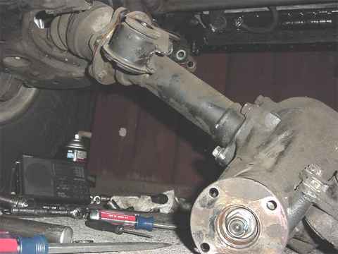
7.5" IFS chunk removal
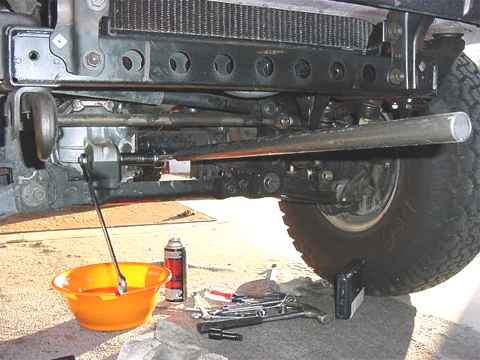
Dropping the front IFS 3rd is easy. Just need some basic tools.......a pair of 14mm closed-end wrenches, a long pair of closed-end 17mm wrenches, a 1/2" ratchet with 19mm socket and a 3 foot cheater bar. .......drain the oil. Use a 15/16"(24mm) socket on the drain plug. 3 large rubber mounts secure the IFS center section in place. 19mm socket. OK to remove the frontal mount bolt in the above pic.
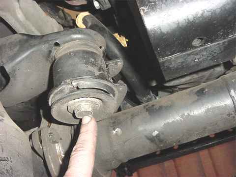
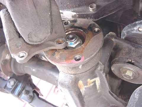
Here's the 2nd one......Use a 19mm or 3/4" shorty wrench to catch the free spinning nut on the topside. Don't remove it yet and leave a couple threads to hold it in. Also, to the left of my finger....remove those six 17mm nuts. The bolts don't turn as they are pressed in but a wrench can be used on them to prevent the CV joint from freely rotating. Again the nuts are really tight.....at least mine were. The joint will then crack apart but won't fully separate yet.
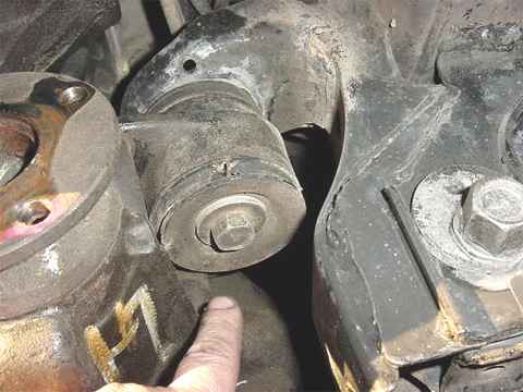
Last big rubber mount...19mm....same thing, loosen it but don't remove quite yet. The nut on the top-side is welded so no wrench needed there. On tight aren't they?
Don't forget to the 6 nuts on the right side CV.....17mm closed-end wrenches....
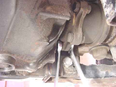
Good time to get the driveshaft out of the way.....I used a pair of long 14mm closed-end wrenches. Mine were on very tight....an open end wrench probably would have rounded all the corners.
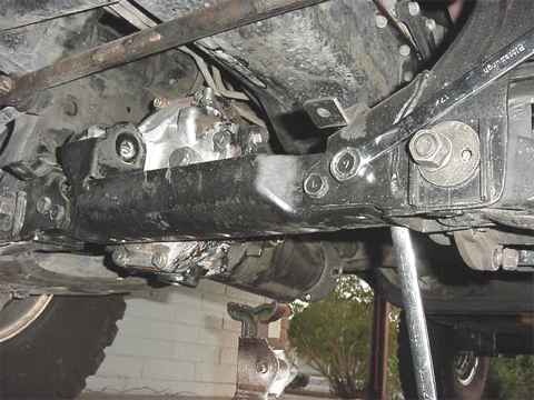
Use a pair of 17mm wrenches to remove the 4 crossbrace bolts/nuts.
Probably best to use a floor jack to support the 3rd while the cross-brace is being wrestled out. Should pretty much drop straight down. Might be a tight fit with rust and such so persuasion might be needed.
Not shown in the above pic, but with the 3rd still supported by a floorjack but lowered down some, it should be fairly easy to use a couple of large screwdrivers to separate the CV's. Pump the floorjack to different heights and it helps in removing the CV ends. Notice that the CV ends are sealed up.....so it's possible to just let them hang, put the cross-brace back in, and drive around town with no 3rd.
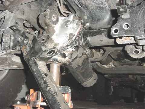
The left side will separate on the top end of that long coupling tube.
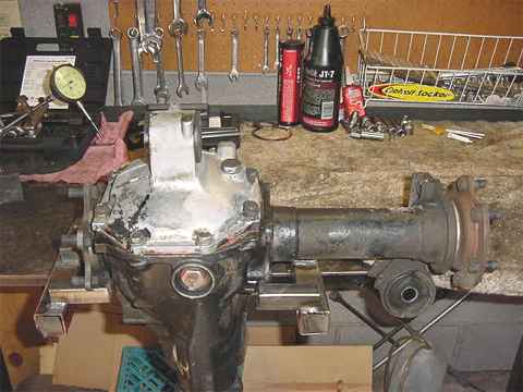
Almost done. Just have to remove the inner axle assemblies.
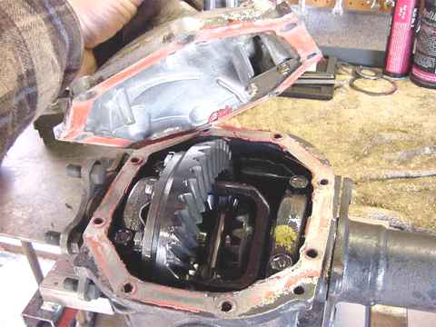
Removed all the 14mm bolts and lifted the cover off. Remove the 4-17mm bolts that hold the right side tube in place.
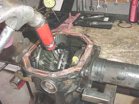
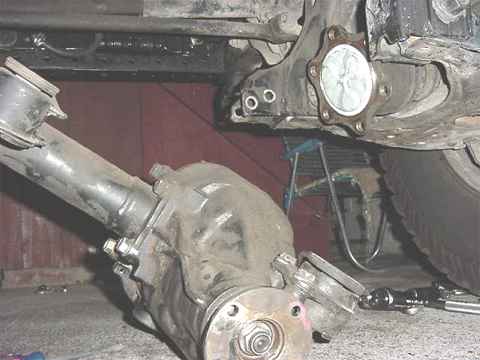
To get the axles out just drive a large screwdriver on each side of the diff center pin......they will push out.
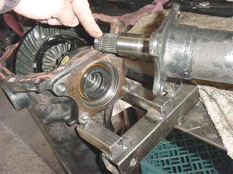
The clips that hold the axles in are similar to the birf clips used on the beam-axle Yotas. Now the 3rd is ready for a re-gear or shipping. Done.
not related to BJ but posting for further reference.
just a quick question on these because it's a little confusing, the c-clip on the axle stubs do they have to be removed before shoving that screwdriver in there to pop them out?
7.5" IFS chunk removal
Dropping the front IFS 3rd is easy. Just need some basic tools.......a pair of 14mm closed-end wrenches, a long pair of closed-end 17mm wrenches, a 1/2" ratchet with 19mm socket and a 3 foot cheater bar. .......drain the oil. Use a 15/16"(24mm) socket on the drain plug. 3 large rubber mounts secure the IFS center section in place. 19mm socket. OK to remove the frontal mount bolt in the above pic.
Here's the 2nd one......Use a 19mm or 3/4" shorty wrench to catch the free spinning nut on the topside. Don't remove it yet and leave a couple threads to hold it in. Also, to the left of my finger....remove those six 17mm nuts. The bolts don't turn as they are pressed in but a wrench can be used on them to prevent the CV joint from freely rotating. Again the nuts are really tight.....at least mine were. The joint will then crack apart but won't fully separate yet.
Last big rubber mount...19mm....same thing, loosen it but don't remove quite yet. The nut on the top-side is welded so no wrench needed there. On tight aren't they?
Don't forget to the 6 nuts on the right side CV.....17mm closed-end wrenches....
Good time to get the driveshaft out of the way.....I used a pair of long 14mm closed-end wrenches. Mine were on very tight....an open end wrench probably would have rounded all the corners.
Use a pair of 17mm wrenches to remove the 4 crossbrace bolts/nuts.
Probably best to use a floor jack to support the 3rd while the cross-brace is being wrestled out. Should pretty much drop straight down. Might be a tight fit with rust and such so persuasion might be needed.
Not shown in the above pic, but with the 3rd still supported by a floorjack but lowered down some, it should be fairly easy to use a couple of large screwdrivers to separate the CV's. Pump the floorjack to different heights and it helps in removing the CV ends. Notice that the CV ends are sealed up.....so it's possible to just let them hang, put the cross-brace back in, and drive around town with no 3rd.
The left side will separate on the top end of that long coupling tube.
Almost done. Just have to remove the inner axle assemblies.
Removed all the 14mm bolts and lifted the cover off. Remove the 4-17mm bolts that hold the right side tube in place.
To get the axles out just drive a large screwdriver on each side of the diff center pin......they will push out.
The clips that hold the axles in are similar to the birf clips used on the beam-axle Yotas. Now the 3rd is ready for a re-gear or shipping. Done.
Last edited by xxxtreme22r; 09-10-2010 at 01:17 PM.
 09-10-2010, 01:13 PM
#1062
Registered User
more reference.
1. Place rear axle securely on jack stands (chock front tires), remove rear tires, and drain differential fluid. Be sure to remove the fill plug before removing the drain plug so that you know you will be able to fill it back up.

2. Next, disconnect brake line (green), e-brake cable (blue), and 4 bolts (red) from the backing plate on the rear drum.

3. Once those are removed, you can simply pull the axle shafts out of the housing. Be sure not to pull the shafts partially out and let them rest on the axle seal because it will ruin your seal. If you are replacing an axle seal, this is the time to do it.

4. Disconnect the rear driveshaft from the pinion flange and remove nuts around the perimeter of the 3rd member. Some trucks may have a rear abs sensor on the top of the differential. This will have to be disconnected as well.

5. With axle shafts removed and everything disconnected from the differential, you can pull the 3rd member straight out from the housing. Be careful because it is heavy! Place it on a piece of wood or cardboard to work on it.

1. Place rear axle securely on jack stands (chock front tires), remove rear tires, and drain differential fluid. Be sure to remove the fill plug before removing the drain plug so that you know you will be able to fill it back up.
2. Next, disconnect brake line (green), e-brake cable (blue), and 4 bolts (red) from the backing plate on the rear drum.
3. Once those are removed, you can simply pull the axle shafts out of the housing. Be sure not to pull the shafts partially out and let them rest on the axle seal because it will ruin your seal. If you are replacing an axle seal, this is the time to do it.
4. Disconnect the rear driveshaft from the pinion flange and remove nuts around the perimeter of the 3rd member. Some trucks may have a rear abs sensor on the top of the differential. This will have to be disconnected as well.
5. With axle shafts removed and everything disconnected from the differential, you can pull the 3rd member straight out from the housing. Be careful because it is heavy! Place it on a piece of wood or cardboard to work on it.
09-10-2010, 01:21 PM
#1063
Registered User
4WD Ball Joint Spacer Installation:
* Block the rear wheels and place the front end of the truck on jack stands and remove the front wheels.
* Remove the original ball joint hardware.
o Knock the studs out of the ball joint with a small hammer.
o This is done most easily if the joint is pressed against the arm supported with a floor jack, as shown below.
* Unbolt the upper shock hardware.
* If you have greaseable ball joints, this is a good time to give them a shot of lubrication.
o Also, if needed, you can swap out an angled grease fitting for a straight one to allow for later greasing.
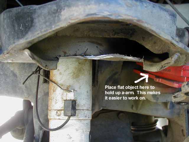
Pic of trimmed a-arm
Trimming around upper ball joint
* Trim the outer lip of the upper control arm (UCA) as depicted in the above picture.
o An angle grinder with a cut-off wheel or a small reciprocating saw works well for this task.
o How much to trim?
+ Just enough to allow installation of the spacer.
* Alternately, you can bend out the outer lip of the UCA with a 2-4 lb. sledge hammer.
Ball joint spacer installation
Ball Joint Spacer Installation
* Put the spacer in place, NOTCH FACING DOWNWARD and, using a floor jack to control arm height, align the ball joint and install the hardware.
o The notch acts as a weep hole to let any water that gets in from above drain out to prevent the ball joint from rusting out.
* Tighten ball joint hardware to 25 ft.lb. or 35 N.m.
o Note: Apply this torque to the allen head bolt and the Grade 10.9 nut only, then install the 2nd nylon lock nut and tighten it down snugly in order to lock the first nut in place. No need to toque the nylon lock nut to 25 ft.lb. value, it may strip.
o If you wish, you can spray the exposed head and threads of the bolts with some paint, as the black oxide coated hardware may tend to rust over time.
* Extend the shock to see if it needs shimming. (it likely will)
o Place the appropriate number of washers to ensure the shock does not limit down travel.
* Tighten shock hardware.
* Repeat for other side.
* Re-install the wheels.
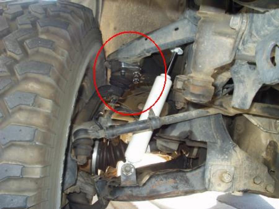
o If the end of the upper control arm is too close to the tire at this point, there are several options:
+ You can try and grind off part of the outer lip of the control arm (area at the left edge of the red circle in the photo above)
+ You can add a 1/4" wheel spacer to move the wheel/tire away from the suspension.
+ You can swap to a narrower tire, for example changing from a 33x12.50 to a 33x10.50 tire will move the inner edge of the tire away from the control arm since it'll have less sidewall bulge on the same wheel.
+ You can swap to a wheel with less back side spacing, for example going from a 4.75" to a 4.5" backspaced wheel will move the inner edge of the wheel and tire 1/4" away from the control arm (stock wheels are ~4.75" backspacing).
* Put the vehicle back on the ground.
* For low profile bump stops only:
o Shim them approx. 1/2" with some washers or use stock bump stops.
o Failure to do so could result in damage to CV joints, shocks, or other components.
o Low profile bump stops are typically made of polyurethane and will be colored red or some other color as shown below.
+ Stock bump stops are typically a black runner material by comparison.

Shimming for low profile bump stops
* Even with stock bump stops, you may experience some CV axle binding.
o To check, let the suspension hang at full droop.
+ Easy to do this when you finish installing the spacers, as the front end should be up in the air.
o Rotate each CV axle shaft by hand and check for any binding at the CV joints and also check with the wheels turned to the steering stops in each direction.
+ Also, you may want to feel the CV axle rotation before installing the spacers, just to familiarize yourself with what they feel like "normally".
o If felt, several options to fix it are available:
+ Add some shims as shown above for the low profile bump stops.
+ Or install a front differential drop kit to lower the differential and thus lessen the CV joint angles.
* Re-adjust torsion bars, if needed
o If the ride height is what you want it to be after installing the ball joint spacers, there is no need to make any adjustments.
o There are good instructions on the 4x4Wire.com Toyota page. and a separate write up on the OffRoad.com Toyota page:
In short:
+ Spray the torsion bar hardware with a penetrating lubricant.
+ Wipe all debris off of the threads.
+ Spray them again.
+ Jack up the front to unload the bars.
+ Adjust them with a 22mm wrench.
+ Lower the truck.
+ Bounce the front end and roll the truck back and forth at least 10 feet.
+ Repeat until the front is level and at desired height.
# The measurement between the fender lip and edge of rim should be about 15 - 15.5".
# This would be the case for 1.5" lift, stock height is 13.5" - 14".
* Get an alignment!
o It has been observed that some driveway alignment adjusting is beneficial and easy to do.
o Following these simple steps will make life easier for the alignment tech who, to be honest, might not be prepared for a vehicle that is any other than bone stock and only slightly out of alignment.
o First make sure the ride height is set to where you want it.
+ If not, adjust it with the torsion bar adjusters
o Loosen the adjustment cams on the lower a-arms making a note of each bolt's orientation.
o Move the lower arms outward until two things happen.
+ (It will likely be necessary to lift the front end while adjusting and roll the truck forward and backward after each adjustment.) One, the tires appear vertical.
+ Two, all cams are adjusted to mirror those on the opposing arm and in a position *closely* relative to where they started. (It is more important that the tires be vertical than the hardware be exactly relative to it's originating position)
+ For example, if the driver's side front cam is pointing straight up and the driver's side rear cam is pointing outward, the passenger side front cam should be straight up and rear outward.
+ If, before adjustment, say the rears were angles outward 30 degrees more than the front, after adjustment the rears should still be outward about 30 degrees. Again this is not as critical as trying to get the tires vertical.
o Adjust the toe by loosening the adjusters and rotating.
+ It is a good idea to lock the steering wheel in a straight position.
+ What you adjust to one side, do to the other. Typically about .5-.25" of toe is fine.
+ If you have trouble measuring, simply attempt to get them straight or angling in slightly.
o You'd be surprised how close one can get these measurements with just the eye.
+ However, perfection is not necessary, this will simply get you in the ball part and help to avoid the "blank stare" when an alignment tech sees his numbers are out and doesn't know which nut to turn which way. (you'd be surprised how often this happens with 4X4s)
o You should recheck the height after this.
+ If you find you adjust the height severely, which is unlikely, and the tires are clearly off (by the eye), repeat these steps.
o Here is a link to a description of a driveway alignment procedure
+ And another link with the same information and photos
o A visit to an alignment shop is definitely recommended!
+ You may need to shop around for a good alignment shop as some may tell you they can't align the truck because it is "modified".
+ Don't be "wowed" by the shop with the fanciest computerized equipment, either. You may find the technicians at such shops may throw up their hands if the computer says the alignment is too far out.
+ Look for a local "mom and pop" shop when they will actually understand how to align the front end and are willing to work with the available adjustments and make it work. There should be adequate adjustment range in the front suspension adjusting cams to handle the ball joint spacers and changed ride height, assuming the front end is not damaged.
* Re-check hardware torque in 2 weeks.
* If you find problems with your CV joints binding due to the steeper angles or find the CV joint boots rubbing and wearing out faster, you might consider adding a front differential drop kit.
* Block the rear wheels and place the front end of the truck on jack stands and remove the front wheels.
* Remove the original ball joint hardware.
o Knock the studs out of the ball joint with a small hammer.
o This is done most easily if the joint is pressed against the arm supported with a floor jack, as shown below.
* Unbolt the upper shock hardware.
* If you have greaseable ball joints, this is a good time to give them a shot of lubrication.
o Also, if needed, you can swap out an angled grease fitting for a straight one to allow for later greasing.
Pic of trimmed a-arm
Trimming around upper ball joint
* Trim the outer lip of the upper control arm (UCA) as depicted in the above picture.
o An angle grinder with a cut-off wheel or a small reciprocating saw works well for this task.
o How much to trim?
+ Just enough to allow installation of the spacer.
* Alternately, you can bend out the outer lip of the UCA with a 2-4 lb. sledge hammer.
Ball joint spacer installation
Ball Joint Spacer Installation
* Put the spacer in place, NOTCH FACING DOWNWARD and, using a floor jack to control arm height, align the ball joint and install the hardware.
o The notch acts as a weep hole to let any water that gets in from above drain out to prevent the ball joint from rusting out.
* Tighten ball joint hardware to 25 ft.lb. or 35 N.m.
o Note: Apply this torque to the allen head bolt and the Grade 10.9 nut only, then install the 2nd nylon lock nut and tighten it down snugly in order to lock the first nut in place. No need to toque the nylon lock nut to 25 ft.lb. value, it may strip.
o If you wish, you can spray the exposed head and threads of the bolts with some paint, as the black oxide coated hardware may tend to rust over time.
* Extend the shock to see if it needs shimming. (it likely will)
o Place the appropriate number of washers to ensure the shock does not limit down travel.
* Tighten shock hardware.
* Repeat for other side.
* Re-install the wheels.
o If the end of the upper control arm is too close to the tire at this point, there are several options:
+ You can try and grind off part of the outer lip of the control arm (area at the left edge of the red circle in the photo above)
+ You can add a 1/4" wheel spacer to move the wheel/tire away from the suspension.
+ You can swap to a narrower tire, for example changing from a 33x12.50 to a 33x10.50 tire will move the inner edge of the tire away from the control arm since it'll have less sidewall bulge on the same wheel.
+ You can swap to a wheel with less back side spacing, for example going from a 4.75" to a 4.5" backspaced wheel will move the inner edge of the wheel and tire 1/4" away from the control arm (stock wheels are ~4.75" backspacing).
* Put the vehicle back on the ground.
* For low profile bump stops only:
o Shim them approx. 1/2" with some washers or use stock bump stops.
o Failure to do so could result in damage to CV joints, shocks, or other components.
o Low profile bump stops are typically made of polyurethane and will be colored red or some other color as shown below.
+ Stock bump stops are typically a black runner material by comparison.
Shimming for low profile bump stops
* Even with stock bump stops, you may experience some CV axle binding.
o To check, let the suspension hang at full droop.
+ Easy to do this when you finish installing the spacers, as the front end should be up in the air.
o Rotate each CV axle shaft by hand and check for any binding at the CV joints and also check with the wheels turned to the steering stops in each direction.
+ Also, you may want to feel the CV axle rotation before installing the spacers, just to familiarize yourself with what they feel like "normally".
o If felt, several options to fix it are available:
+ Add some shims as shown above for the low profile bump stops.
+ Or install a front differential drop kit to lower the differential and thus lessen the CV joint angles.
* Re-adjust torsion bars, if needed
o If the ride height is what you want it to be after installing the ball joint spacers, there is no need to make any adjustments.
o There are good instructions on the 4x4Wire.com Toyota page. and a separate write up on the OffRoad.com Toyota page:
In short:
+ Spray the torsion bar hardware with a penetrating lubricant.
+ Wipe all debris off of the threads.
+ Spray them again.
+ Jack up the front to unload the bars.
+ Adjust them with a 22mm wrench.
+ Lower the truck.
+ Bounce the front end and roll the truck back and forth at least 10 feet.
+ Repeat until the front is level and at desired height.
# The measurement between the fender lip and edge of rim should be about 15 - 15.5".
# This would be the case for 1.5" lift, stock height is 13.5" - 14".
* Get an alignment!
o It has been observed that some driveway alignment adjusting is beneficial and easy to do.
o Following these simple steps will make life easier for the alignment tech who, to be honest, might not be prepared for a vehicle that is any other than bone stock and only slightly out of alignment.
o First make sure the ride height is set to where you want it.
+ If not, adjust it with the torsion bar adjusters
o Loosen the adjustment cams on the lower a-arms making a note of each bolt's orientation.
o Move the lower arms outward until two things happen.
+ (It will likely be necessary to lift the front end while adjusting and roll the truck forward and backward after each adjustment.) One, the tires appear vertical.
+ Two, all cams are adjusted to mirror those on the opposing arm and in a position *closely* relative to where they started. (It is more important that the tires be vertical than the hardware be exactly relative to it's originating position)
+ For example, if the driver's side front cam is pointing straight up and the driver's side rear cam is pointing outward, the passenger side front cam should be straight up and rear outward.
+ If, before adjustment, say the rears were angles outward 30 degrees more than the front, after adjustment the rears should still be outward about 30 degrees. Again this is not as critical as trying to get the tires vertical.
o Adjust the toe by loosening the adjusters and rotating.
+ It is a good idea to lock the steering wheel in a straight position.
+ What you adjust to one side, do to the other. Typically about .5-.25" of toe is fine.
+ If you have trouble measuring, simply attempt to get them straight or angling in slightly.
o You'd be surprised how close one can get these measurements with just the eye.
+ However, perfection is not necessary, this will simply get you in the ball part and help to avoid the "blank stare" when an alignment tech sees his numbers are out and doesn't know which nut to turn which way. (you'd be surprised how often this happens with 4X4s)
o You should recheck the height after this.
+ If you find you adjust the height severely, which is unlikely, and the tires are clearly off (by the eye), repeat these steps.
o Here is a link to a description of a driveway alignment procedure
+ And another link with the same information and photos
o A visit to an alignment shop is definitely recommended!
+ You may need to shop around for a good alignment shop as some may tell you they can't align the truck because it is "modified".
+ Don't be "wowed" by the shop with the fanciest computerized equipment, either. You may find the technicians at such shops may throw up their hands if the computer says the alignment is too far out.
+ Look for a local "mom and pop" shop when they will actually understand how to align the front end and are willing to work with the available adjustments and make it work. There should be adequate adjustment range in the front suspension adjusting cams to handle the ball joint spacers and changed ride height, assuming the front end is not damaged.
* Re-check hardware torque in 2 weeks.
* If you find problems with your CV joints binding due to the steeper angles or find the CV joint boots rubbing and wearing out faster, you might consider adding a front differential drop kit.
Last edited by xxxtreme22r; 09-10-2010 at 01:23 PM.
09-10-2010, 01:32 PM
#1064
Registered User

trucks (except Tacoma) '86-'95. These springs, as with all springs "sag" with time and use. Off-road driving accelerates this sag. Front torsion bars can be easily adjusted and the front suspension can be returned to the factory height or even lifted about 1.5"- by just turning a bolt!
If you drive off-road more than the average driver than you may want to consider using heavy duty torsion bars. These bars won't bend as easily and don't require readjusting after harsh driving. Heavy duty bars also give a slightly stiffer ride and prevent bottoming out of the suspension. The stock torsion bar is 22.8mm, heavy duty bars are available in 24mm and 26mm sizes. The 26mm size is the most common and is available from many offroad parts companies.
ADJUSTING TORSION BARS
Jack up the front of the truck at the front IFS cross member to get the wheels off the ground and to let the strain off the torsion bars. This must be done or you will destroy the adjuster bolts. Don't forget safety, put a pair of jackstands under the truck before you start working under it.
The torsion bar adjuster bolts are located under the truck near the frame rails about 10" back from the transfer-case cross member. Spray the bolt threads with WD-40 or similar.

If you have a '86-'88 you may have a lock nut that must be removed before adjusting your bars. If your truck has this lock nut it may be difficult to remove. You may need to add a pipe on the end of your wrench to get this nut loose. This design was changed sometime in 1988 to the type shown below.

This is a picture of the adjuster bolt and nut from truck in the '88 - '95 range. If you have this type, there is no locknut to remove.
Now Tighten the 22mm bolt head a few turns (5 to 10 revolutions). Look at the upper nut when doing this, it should not turn, the bolt should turn inside without turning the nut. If the main nut turns with the adjusting bolt then you may already have a bad bolt bad in need of replacement. You should replace the nut and bolt as a set for about $6 at any Toyota dealer.
You can put a wrench on the main nut while turning the bolt head but if it is hard to turn the bolt head it's time to replace the main nut and bolt. Do the same adjustment to the other side of the truck. Turning the bolt the same number of times. Here you can click to see what a new set of bolts looks like.
 09-10-2010, 01:37 PM
#1065
Registered User
These instructions are designed to help the 4wheeler align their own vehicle after installing a lift and also after hard off road use.
Camber: Looking at the truck head on, positive camber is where the wheels lean outwards, negative is inwards.
Caster: This is the rake of the wheel spindles. It should be such that they lean back like the forks on a motorcycle.
Toe: This is the angle of the tires normal to the pavement plane. If the tires are pointing at each other, they are toed in, if pointing away, toed out.
Procedure:
1. Pull the truck straight onto a flat surface, turn off the truck and so the steering wheel locks straight.
2. Make sure the truck is level. This will require adjusting the torsion bars if it is leaning to one side. This step is important so take your time. Pick a spot on the frame on each side of the truck and measure it against the ground. Adjust until it is level.
3. Check the camber with a right angle like this. Although the spec says 0-1.5, I have a -.5 (set by the dealer) and the truck drives very well.

Setting camber
4.
If it is not vertical, loosen the cams and adjust them inwards or outwards. NOTE: You want the rear bolts to point outwards more than the fronts as pictured. This brings the caster into where it should be while increasing firewall clearance. You will likely have to roll the truck back and forth to allow the tires to relax as pushing out the rim will flex the sidewalls a bit making it hard to align to the square. You can use a small ruler and easily get to where the distance between the top and bottom side surfaces within .125". (1/8) Here, symmnetry is desireable. If one tire is cambered outwards a bit, so should the other one. You don't want the tires parallel to one another. Toyota's spec is 0 to 1.5 degrees out. Adjust the cams as pictured below, this will get the caster within spec
5.


Front camber adjusters
Rear camber adjusters
6.
Tape a string to the front wheel and walk with it to the rear of the truck. Measure against the front and rear outter surfaces of the rear wheel. NOTE: The string should not rest flat against the rear wheel due to the front track width being greater than the rear. The string should be the same distance from the sides indicating the front wheel is pointing the same direction as the rear. If it isn't, loosen the adjuster on the tie rod and tweak it until the front wheel is straight. You can use a small ruler and easily get to where the distance between the side wheel surfaces within 0- .0625". (1/16) At that difference, the front wheel is toed in appropriately.
7.

Setting toe
8. Repeat these steps periodically rolling the truck back and forth to releive tension on the tires between adjustments.. By keeping the steering wheel centered during the forward/backward rolling you ensure it stays centered on the road.
9. The inital alignment after a lift can take a while. However, "touchups" can be done quickly thereafter. Also, now when you wonder how the truck will perform if you adjust your torsion bars one way or the other, you can do so without the $50 alignment bill thereafter.
Camber: Looking at the truck head on, positive camber is where the wheels lean outwards, negative is inwards.
Caster: This is the rake of the wheel spindles. It should be such that they lean back like the forks on a motorcycle.
Toe: This is the angle of the tires normal to the pavement plane. If the tires are pointing at each other, they are toed in, if pointing away, toed out.
Procedure:
1. Pull the truck straight onto a flat surface, turn off the truck and so the steering wheel locks straight.
2. Make sure the truck is level. This will require adjusting the torsion bars if it is leaning to one side. This step is important so take your time. Pick a spot on the frame on each side of the truck and measure it against the ground. Adjust until it is level.
3. Check the camber with a right angle like this. Although the spec says 0-1.5, I have a -.5 (set by the dealer) and the truck drives very well.
Setting camber
4.
If it is not vertical, loosen the cams and adjust them inwards or outwards. NOTE: You want the rear bolts to point outwards more than the fronts as pictured. This brings the caster into where it should be while increasing firewall clearance. You will likely have to roll the truck back and forth to allow the tires to relax as pushing out the rim will flex the sidewalls a bit making it hard to align to the square. You can use a small ruler and easily get to where the distance between the top and bottom side surfaces within .125". (1/8) Here, symmnetry is desireable. If one tire is cambered outwards a bit, so should the other one. You don't want the tires parallel to one another. Toyota's spec is 0 to 1.5 degrees out. Adjust the cams as pictured below, this will get the caster within spec
5.
Front camber adjusters
Rear camber adjusters
6.
Tape a string to the front wheel and walk with it to the rear of the truck. Measure against the front and rear outter surfaces of the rear wheel. NOTE: The string should not rest flat against the rear wheel due to the front track width being greater than the rear. The string should be the same distance from the sides indicating the front wheel is pointing the same direction as the rear. If it isn't, loosen the adjuster on the tie rod and tweak it until the front wheel is straight. You can use a small ruler and easily get to where the distance between the side wheel surfaces within 0- .0625". (1/16) At that difference, the front wheel is toed in appropriately.
7.
Setting toe
8. Repeat these steps periodically rolling the truck back and forth to releive tension on the tires between adjustments.. By keeping the steering wheel centered during the forward/backward rolling you ensure it stays centered on the road.
9. The inital alignment after a lift can take a while. However, "touchups" can be done quickly thereafter. Also, now when you wonder how the truck will perform if you adjust your torsion bars one way or the other, you can do so without the $50 alignment bill thereafter.
09-10-2010, 01:49 PM
#1066
Registered User
hey swimmer find out if that add-a-leaf kit comes with a new center locating pin would ya. not sure if I am gonna have to grind that off and use a new one.
swimmer or 92Toy you got one of those right angle's? I dont.
swimmer or 92Toy you got one of those right angle's? I dont.
09-10-2010, 02:11 PM
#1068
Registered User
09-14-2010, 04:23 AM
#1070
YotaTech Milestone-Two Millionth Post
looking for a status report here......i don't want you stranded at my house...hehehehe....no really.
OK....here's what i have that i think we need.
2 tall jack stands.
3 ton floor jack.....2 bottle jacks
angle grinder (brian buy some discs, i'll let you know what size,,,????? 3inch, 4 inch???)
breaker bar 1/2'' drive........largest socket i have is 19mm
cheater bar
ambiance
just to let you know......i live in the middle of nowhere.......22 miles to the nearest autozone (and that's the closest store of it's kind)....so if you are in doubt if we are gonna need it....buy it.....cuz running in circles is going to waste time.
secondly, get with XXXTREME .....i have no clue about what we are gonna do, i can provide some muscle and some tools but knowledge-wise, i have no clue about this
09-14-2010, 04:58 AM
#1071
Registered User
yeah and I suggest we start early like 8am early. lol. Jerry, hes gonna need to know the diameter and chuck size of those discs and pick up some grinding and cut-off discs. Not sure what I am gonna need as I never did the BJ's before. if you have a cordless impact bring it. I have a few sockets bigger than 19mm. not sure if I will need em though.
Jerry all the info (I think) anyway) is in the above few posts from me. I also have some jacks stands (not the greatest though) a 2 ton hydraulic floor jack and my hi-lift.
Not sure what I am gonna do first. the AAL, BJ's or the gears. I think it would be kinda fun to do the gears first and roast some tires with the 4:56's lol.
Jerry all the info (I think) anyway) is in the above few posts from me.
I also have some jacks stands (not the greatest though) a 2 ton hydraulic floor jack and my hi-lift. Not sure what I am gonna do first. the AAL, BJ's or the gears. I think it would be kinda fun to do the gears first and roast some tires with the 4:56's lol.
09-14-2010, 06:23 AM
#1072
 09-15-2010, 01:07 AM
#1078
Registered User
Join Date: Mar 2010
Location: SE PA.
Posts: 348
Likes: 0
Received 0 Likes
on
0 Posts
4 jackstands would be a lot nicer. cut off wheel for front aframe- permatex for gear housing -gear oil plenty of washers after installing bj kit you want to let suspension droop and put the washers under bump stop so axles do not bind pay attention to passenger side . do not forget difff drop kit. 1:00 you can burn tires with whole truck lifted and everyone working
09-15-2010, 03:50 AM
#1079
YotaTech Milestone-Two Millionth Post
thanks for the info...
XXXTREME....bring your jack stands
Brian.....angle grinder is 4 1/2''.....so buy plenty of whatever we are going to need to make this happen.
i still have your cellphone # and i assume you still have mine.....i will PM you my address for what it's worth, but i truly think i should land you somewhere else and i will arrange a police escort to bring you the rest of the way (not really, but it sounded cool).....the last 8 miles or so can be tricky (or not so much.....since it's really only 2 turns....but out here if you make a wrong turn you will drive forever and not really end up anywhere)
so i think i will give you an address (in addition to mine) where we, or XXXTREME can either meet up with you there and bring you in or at least guide you in by phone (that's the other thing....VERIZON is fine out here with about 2 miles of deadness on the ride here, but other carriers are not so good).
my warning though.....make sure you have everything you need and then some....the nearest place to even buy a stick of gum is about 3 miles away, auto parts stores more than 20 miles away.
i'd be curious to know what the directions will be to my house......basically need to get to interstate 81 to route 29 to route 11 then blah-blah-blah
09-15-2010, 03:51 AM
#1080
Registered User
wow, didn't think of the washers for the bump stops. any idea on what size hole for them? I got a bunch of grade 8 1/2" ones in my took box. if not I can run into Tractor supply company for a few.
I don't think he has the diff drop kit, is it really nec with the 2" BJ lift anyway? I will bring my other 2 jack stands.
I don't think he has the diff drop kit, is it really nec with the 2" BJ lift anyway? I will bring my other 2 jack stands.


