When you click on links to various merchants on this site and make a purchase, this can result in this site earning a commission. Affiliate programs and affiliations include, but are not limited to, the eBay Partner Network.
Would you mind posting some pics of your Pair and EGR systems? I bought my '86 Runner here in Menifee, CA and the PO began the EGR and PAIR delete. I think I have all the EGR system intact, but the PAIR system is gone. I've found parts for what I think I need, but every diagram I fond online shows the later setup where there is a pipe coming off the resonator going to the air filter box. The newer boxes have an elbow for that pipe to connect to, but mine does not.
Also, think you could help with a wiring issue? My left turn signal turns on solid (front and rear) when the headlights are turned on, and using it with the lights off causes the clock to flash. Any ideas?
Hey, Ray! Great thread, and better rig!
Would you mind posting some pics of your Pair and EGR systems?...
Also, think you could help with a wiring issue? My left turn signal turns on solid (front and rear) when the headlights are turned on, and using it with the lights off causes the clock to flash. Any ideas?
Thanks but sorry, I'm not not exactly sure of where the Pair and EGR parts are, either. In fact, I'm wondering where the EGR cooler (if it exists) on the 1986 because a post says if it's clogged, hot exhaust would go into the intake - and might be a contributor to my one-time running hot issue that I'm still trying to monitor/troubleshoot.
Pretty busy at work. When I get the chance to look at FSM for general idea of locations, I'll take pics.
Dang, I was driving between SD and Riverside this weekend; I cold have swung by
Lights seems to be a wiring issue. Does it happen both with taillights as well as headlights?
If it happens even with taillights only, I would suspect the rear socket that houses the dual-filament 1157; common pin goes to ground, 9W filament taillight, 23W filament is Turn signal.
Please start a "Turn Signals Troubleshooting Thread For First-Gen 4Runners" under 1986-1995 Trucks forum. We'll work on it there. Try disconnecting the connector to the left taillights and let us know.
Possibly a tailer harness tapped into stock wiring. Those suck. Or a short in your dimmer-combo-turn-headlights stalk switch.
Cheers!
Thanks but sorry, I'm not not exactly sure of where the Pair and EGR parts are, either. In fact, I'm wondering where the EGR cooler (if it exists) on the 1986 because a post says if it's clogged, hot exhaust would go into the intake - and might be a contributor to my one-time running hot issue that I'm still trying to monitor/troubleshoot.
Pretty busy at work. When I get the chance to look at FSM for general idea of locations, I'll take pics.
All 22R or 22R-E engines that were equipped with an Exhaust Gas Recirculation (EGR) Valve has an EGR cooler plate located right on the back of the head, just below the "half moon" seal. There is coolant behind that plate, and thus cools the exhaust gases.
Here is a little graphic 22RE Performance made of the EGR and Air Injection / Air Suction systems. Note: 22R-E engines did not get the Air Injection / Air Suction system until 1988.
If the EGR Cooler was blocked up by carbon, it would act just as if the EGR valve was stuck closed, and little to no flow should make it to the intake.
I'm concerned about leaving my lights on and draining the battery. Per FSM, the light reminder relay is supposed to be here, but I only see a mounting hole on mine, confirming my suspicion that the light reminder circuit was only available on SR5 first-gens. Therefore, one lazy afternoon, I got busy
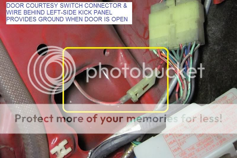
The circuit is simple. It will energize when there is positive voltage from the tail light circuit AND ground via the the driver side door courtesy switch when door is opened. (When headlights are on, there is also power to tail light circuit.)
Parts & Equipment Needed:
Buzzer PN 273-059 from Radioshack. I used an overhand knot and ran lead wire through mounting hole for strain relief. Also affixed foam-backed double-sided tape for mounting.
LED indicator light. (I used an LED lying around in my toolbox and appropriate resistor.) Easier to simply buy pre-assembled indicator LED light (i.e., from O'Reilly)
To Install:
Remove Left hand dash panel that covers the instrument panel and holds the Clutch Safety Cancel switch.Attachment 191730 Attachment 191731
Wher to get positive 12V power
Remove left-hand kick panelAttachment 191732
Remove Tail Fuse (15A). Verify that left terminal (marked below) is the supply side by measuring +12V when tail light switch is in ON position, 0 volt when tail light switch is OFF. It is important that you connect to supply side of fuse so that IF headlight is on and even if tail fuse is blown, this will still power the reminder circuit.
NOTE: The cleaner method would be to solder it into the circuit in the back of the fuse block, which I would do later.
Slip red wire into supply side, and re-install fuse. Be careful that you do not cut strands that might fall on other circuits and cause shorts.Attachment 191733
NOTE: The cleaner method would be to solder it into the circuit in the back of the fuse block, which I would do later.
An option is to take positive voltage from this green wire (the section in yellow heat-shrink) that once supplied stock deck lamp circuit, but I disconnected in order to do my deck lamp retrofit. Verify that this green wire has 12V when, and only when, tail light is on.
Strip door courtesy switch wire at a convenient spot and connect ground side of circuit to that. Soldering then insulating with heat-shrink tubing or electrical tape is recommended.
Here's the circuit connected and properly labeled. Buzzer is stuck on fuse block with foam-backed tape. [Let us keep our wiring and and mods clean & properly documented to make it easy to troubleshoot or return to stock when needed/desired. This way our classic rigs can be considered improved, not molested. ]Attachment 191735
I just got around to putting this together. Thanks for the write up. Don't know why I waited so long. It's so easy.
LOL! Yeah, life gets in the way.
I was forced to do it the second time I discharged my battery from leaving headlights on.
Hoping you, Yota brethren and loved ones are well.
Juggling between cooling system and looking cool
I guess this project would be halfway between touching up and repainting, because I don't really want to spend too much time, money on total repaint nor inhale too much paint spray - proper respirators not available at stores .
Got some rust spots on roof so I sanded down rusted area down to bare, shiny, metal, with 100 grit sandpaper.. I applied Permatex rust converter to exposed metal for extra measure. Feathered that and sanded exposed good primer and good paint with 200 grit. Also did the rusted part of the windshield surround, because I was too lazy to paint over the POR-15 - That stuff is not UV-resistant.
FACTORY CODE SPRAY CANS, Toyota Paint Code 3D7: Approx $30 per 12-oz can
So far, I am very happy with Spray Max cans with hardener from Body Shop Supplies Lemon Grove, CA. I called order in for Toyota Paint Code 3D7, and picked it up after about an hour. Spray pattern is very clean and predictable. The only cause for failure would be my prep and application technique.
My only gripe is the instructions on can are not clear. There is pin and a push handle on bottom, but I had to go online for clear instructions to push hard on pin "until it pops".
BEFORE:
AFTER TWO COATS ON ROOF AND WINDSHIELD SURROUND:
AFTER FIRST COAT ON ROAD RASH ON FENDER.
I think the stock and oversprayed paint will match when I hit it with TR3 polish/cleaner.
i also think where I had to prime, it would have been better to feather the primer spray than to mask it. Should look better after a 2 more coats, though.
I plan to use same paint for the cap which has faded again.
I have used 2 cans, so far. A third can should finish up the main cab and fender touch-ups.
Another 2 cans for the fiberglas cap.
Last edited by RAD4Runner; 05-20-2020 at 03:42 PM.
Fun stuff, Ray. Is there clearcoat on the original paint? I think not.
Agree, don’t mask primer. In fact, if the base paint is still well-adhered to the metal just scuff, and paint over it. Spot prime areas where sanding has gone thru to metal.
Also use wax and grease remover to clean panels before sanding to make sure you are not spreading contaminants around as you sand. Use it again before color. And yeah, all this is more fun with a decent respirator. I was pleased with the HF one i used on my bodywork, now out of stock as you suggest.
#1 tip- take the advice of the guys at the autobody supply store! They sure helped me get through the learning curve.
Just to be clear, the dow 995 silicone is what you will be using for the rain gutters? I need to do mine also. Those gutters get pretty tight down next to the windshield.
Fun stuff, Ray. Is there clearcoat on the original paint? I think not....
Correct. No clearcoat on first -gen. That's what we see that is peeling off on 3rd-gen 4Runners (and other models of those years). Nothing peels off first-gens; it's more gradual wearing out from particles hitting it at high speeds over the years. most of the original paint is good so I only want to touch up where topcoat is worn out.
Just to be clear, the dow 995 silicone is what you will be using for the rain gutters? I need to do mine also. Those gutters get pretty tight down next to the windshield.
I bought black Dow 995 Silicone to fill gap around the windshield. Extra protection for paint and urethane adhesive used to adhere glass, additional seal, would not trap moisture like any trim and would be smoother than any trim so hopefully a tiny less wind noise. Instead of acetic acid, it uses Stearic Acid which I gather is used to prevent further rust if any (Google here).
For sealing the gutter seam, Try to find flowable seam sealer or one with very thin applicator tip. I bought AC Delco seam sealer but it is hard to get it into the A-pillar gutter on driver side, is very messy (masked surrounding area and I used my backpacking white gas and and rag to quickly wipe down stains). Where I was able to apply on passenger side, it is taking forever to cure.
An option I am thinking of is:
1) Prime and paint inside gutter as usual,
2) Properly mask, then Flow flowable silicone into any crevices,
3) While flowable silicone is tacky, FILL the gutter with Dow 995. The gutter is pointless, and only means trouble because it causes rust. The roof gutter construction is also poor. Worn out seam seal caused leak into my cabin.
I do not see any problem with newer vehicles without it. In fact Arlindsay (AlexmandVideos on Youtube) removed his A=pillar rain gutter.
Last edited by RAD4Runner; 05-26-2020 at 09:58 AM.
 02-24-2020, 08:48 AM


 .
.