
Transplanter's OM617 FAQ
 Feb 19, 2013 | 01:44 PM
#1

Thread Starter
Registered User
Joined: Jan 2012
Posts: 53
Likes: 0
Transplanter's OM617 FAQ
Since you are the foremost expert in the field of OM617's, why don't you share some of the info you have floating around in your head. Maybe the YCE's (Yotatech Certified Experts) will stop expressing their opinions if we have the knowledge you posses.
Never said or claimed to be the expert, but you sure sound like you know everything about these. I share my experience and the things I learned from messing with my swap to try and help people solve the problems they are having or have questions about. That is what these forums are about.
I had two different engines, one had the headgasket let go by the rear oil passage between the head and block, the other the turbo ate itself. I have my reasons for not continuing with the diesel and I have openly expressed them here and elsewhere. The engines were running right, but you would assume I didn't know what I was doing so you can try to belittle me on the forum. Good way to show yourself, hopefully you don't run your business with the same attitude. You say I spread misinformation, well where is your dyno charts to show how great the power is on your truck? You are trying to make the engines sound better than they are so you can get more customers, selling pipe dreams I say. The only person that I ever saw with a dyno for a om617 was ForcedInduction and he had 140 hp and 194 lb-ft of torque. Maybe he didn't have it set up that great, but remember he worked on these engines for a living too.
The reason I say these are not a performance engine is because no one is keeping them alive around the 300 hp level. If that is Hi Performance to you, maybe you need to hang out with some sports cars at a track. If you notice, most of the people that blow up their OM617 due to performance mods, they usually give up on it and go to a 603 and up. Those engines can take the added stress from high boost and spirited driving. There is no comparison in power potential between the OM603, 604,605,and 606 when looking at the OM617. It's a engine built for longevity and economy, not pushing 25-30 lbs of boost through and expecting it to hold up for 500,000 miles. The heads can barely support 300 hp worth of air and there isn't much room for porting and larger valves. The other problem is they are a really tight fit in a Toyota pickup or 4runner, that is why I say it isn't worth the work to install one. A person could spend the same amount of time and work putting in a larger displacement 4cyl engine and have a better return on their investment across the board.
As for being lonely, hahaha. I know two other people that swapped a OM617 and pulled it for other engines. They went with 3rz's and they said the power was night and day (both of them did it for wheeling). One other thing I noticed about the OM617 is they don't like to be on a steep incline for long periods of time like when 4wheeling. Mr_Manny comes to mind as well as the second engine I had put in my 4runner. They starve for oil when you bounce around with the front pointed to the sky. That and it not having enough power to spin 42's effectively made me go with my $200 1uzfe over the OM617. BTW, my cousin had a woman come by his shop with a OM617 swapped CJ complaining about it being gutless. His reply to her was to swap in a Lexus V8.
I know you will probably still try to make me look bad, but I don't really care. I like to share information with others so they can try to make a good decision on their projects. If you ever come out this way, look me up. You can come see my POS 4runner that I have no clue how to work on.
So tell us all about how you are the expert on om617 performance and know more about thier potential than somone who does it for a living? Is it because you are the only person on this planet that has gone through 3 om617s in his rig because he couldnt figure out how to get them to run correctly in the first place? How many diesels are made as a (performance engine) in the first place? I have read the advice that you have given out on other forums and unless you actually know what you are talking about, wich when it comes to Mercedes diesels, you obviously dont know as much as you think and have been giving uneducated and incorrect advice. And congrats, I think you are the only person on this planet that has something bad to say about an om617 swap... lonely?
I had two different engines, one had the headgasket let go by the rear oil passage between the head and block, the other the turbo ate itself. I have my reasons for not continuing with the diesel and I have openly expressed them here and elsewhere. The engines were running right, but you would assume I didn't know what I was doing so you can try to belittle me on the forum. Good way to show yourself, hopefully you don't run your business with the same attitude. You say I spread misinformation, well where is your dyno charts to show how great the power is on your truck? You are trying to make the engines sound better than they are so you can get more customers, selling pipe dreams I say. The only person that I ever saw with a dyno for a om617 was ForcedInduction and he had 140 hp and 194 lb-ft of torque. Maybe he didn't have it set up that great, but remember he worked on these engines for a living too.
The reason I say these are not a performance engine is because no one is keeping them alive around the 300 hp level. If that is Hi Performance to you, maybe you need to hang out with some sports cars at a track. If you notice, most of the people that blow up their OM617 due to performance mods, they usually give up on it and go to a 603 and up. Those engines can take the added stress from high boost and spirited driving. There is no comparison in power potential between the OM603, 604,605,and 606 when looking at the OM617. It's a engine built for longevity and economy, not pushing 25-30 lbs of boost through and expecting it to hold up for 500,000 miles. The heads can barely support 300 hp worth of air and there isn't much room for porting and larger valves. The other problem is they are a really tight fit in a Toyota pickup or 4runner, that is why I say it isn't worth the work to install one. A person could spend the same amount of time and work putting in a larger displacement 4cyl engine and have a better return on their investment across the board.
As for being lonely, hahaha. I know two other people that swapped a OM617 and pulled it for other engines. They went with 3rz's and they said the power was night and day (both of them did it for wheeling). One other thing I noticed about the OM617 is they don't like to be on a steep incline for long periods of time like when 4wheeling. Mr_Manny comes to mind as well as the second engine I had put in my 4runner. They starve for oil when you bounce around with the front pointed to the sky. That and it not having enough power to spin 42's effectively made me go with my $200 1uzfe over the OM617. BTW, my cousin had a woman come by his shop with a OM617 swapped CJ complaining about it being gutless. His reply to her was to swap in a Lexus V8.
I know you will probably still try to make me look bad, but I don't really care. I like to share information with others so they can try to make a good decision on their projects. If you ever come out this way, look me up. You can come see my POS 4runner that I have no clue how to work on.
Last edited by 89lc; Feb 19, 2013 at 07:53 PM.
Feb 19, 2013 | 03:43 PM
#2
Thread Starter
Registered User
Joined: Jan 2012
Posts: 53
Likes: 0
IP theory written by OM616 on STD
The following information is independent of any Bosch documentation, mainly because Bosch only has specifications and procedures for setting up stock pumps for specific applications.
I have attended a training class and talked with the trainers, and I was surprised to learn that there was not any knowledge of how to set up a pump outside of following the procedure.
Even they did not know how to restore the Idle stability after turning in the Torque Control Capsule beyond spec.
Their response was to return all the adjustments to their ruff settings and reset the Governor to Stock settings.
I thought about showing them how to do it, but I sensed that the idea of altering a setting beyond spec was forbidden, and I did not want to upset anyone.
I have built an instrument interface that allows me to digitally measure the variables, (Rack position, RPM, Injector out put, etc), which allows me to see the actual fueling curve that is delivered from the injector.
That information allows me to graph the curve much like a dyno graph.
With the addition of intake air flow volume at different levels of boost, I can calculate the air/fuel ratio at any point on the fuel curve based on the boost pressure.
The end result is a known boost curve requirement in order to prevent smoke, based on the known fueling curve.
MW IP RW Governor description
Inside the case of a RW Governor are actually three individual governors which use a common set of flyweights.
They are:
● The Idle Governor
● The Torque Control Governor
● And the Max Speed Governor.
Although each governor handles a specific range of operation, because they share a common set of flyweights, altering the setting of one governor can affect another.
For instance, the common issue with a Torque Control adjustment is that it can affect the idle quality which is controlled by the Idle Governor.
With a proper understanding of what each of the Governors do, and how they do it, each adjustment can be maximized, and any secondary ill effects after an adjustment of a individual governor can be corrected, resulting in a proper adjustment.
Common complaints resulting from improper adjustments are the lack of return to idle after a Torque Control adjustment, and very little change after removing the Rack Limiter.
NOTE: I do not recommend the removal of the Rack Limiter.
It plays a very important role in a proper adjustment as it sets the end of injection.
This is very important as, if the end of injection is too late, quick rising and high EGTs will result.
I have performed several IP adjustments and corrections, each time refining my process and the rack limiter is the last setting I adjust, and it doesn’t take much.
It is also important to keep a log of all adjustments made.
Read all the information bellow before preceding with an adjustment.
Governor Adjustments:
● Throttle Max Tension (Horizontal Throttle Stop)
● Throttle Min Tension (Vertical Throttle Stop)
● ALDA / ADA Compensation Rod Height
● Max Speed Governor Spring Tension
● Idle Governor Spring Tension
● Torque Control Capsule Depth
● Rack Limiter
● Restoring return to idle
● Setting Idle speed 240D
Pump Adjustments:
● Delivery Valves
● Element Barrel Position, (Turning Delivery Valve Holders)
Incidentals:
● Helpful Hints
● Start Up Procedure
How it works.
Throttle Tension
Note: This is the easiest way I can think of to explain the throttles influence in the over all operation. It is actually a little more complicated, but the end result is what counts here.
How fast the operator wants to go is transmitted from the pedal, to the Throttle Lever, and from the Throttle Lever to the governors, through a series of levers and springs, inside the housing.
When the Throttle Lever is moved to increase engine speed, the Throttle Tension is increased and the Rack is pushed forward, (increasing fuel).
As the speed increases, the Flyweights, connected to the rack, through a series of levers, start to over power the Throttle Tension, and pull the Rack back, (reducing fuel).
When the Flyweight force balances the Throttle Tension force, the engine speed will be maintained.
If the Throttle Tension is increased, the Rack is pushed forward. If the Throttle Tension is reduced, the Rack is pulled back.
When you stop the engine using the stop lever on the valve cover, what happens is the Throttle Tension is actually pulling the Rack back, to the point where the fuel is cut off.
When you use the key to stop the engine, the vacuum diaphragm adds the needed force to over come the Throttle Tension, and pulls the Rack back to the point where the fuel is cut off.
There is actually more going on, but this is intended to give you a basic idea of how it works. You will learn about what I have not mentioned up to this point later.
The Idle Governor
The next step is to regulate the engine idle speed. This is done by the Idle Governor. The Idle Governor consists of a long strip of spring steal and it is not a very strong spring, it has to be week because the Flyweight forces at idle speeds are relatively light, and if the Idle Spring was too strong, it would be impossible to regulate a low idle speed.
To help the Idle Spring out when it needs a little more power, a Bump Stop Spring was added. When both the Throttle Tension and Idle Governor Spring Tension are set and balanced properly, if the Throttle Lever is moved quickly, from say 25% (for example), throttle to the Idle position, the strong force of the fly weights easily overpowers the Idle Governor Spring, and pushes it back into the Bump Stop, compressing the Bump Stop Spring, and pulling the Rack back to, or close to the fuel cut off point.
The addition of the Bump Stop makes the Idle Governor Spring into a two stage spring, and when the engine speed reaches the set point, the Bump Stop Pushes the Flyweights back, and the engine “catches” and Idles. When within the idle speed range, the Idle Governor Spring is able to do its job without the assistance of the Bump Stop.
So to recap, the Idle Governor Spring regulates the idle speed, and the Bump Stop Spring helps the Idle Governor Spring, by pushing the Rack in from the fuel cut off point when the engine RPM reaches just bellow the set Idle speed, (when the engine speed reaches the point where the Bump Stop Spring Tension is grater than the Flyweight force).
It is important to note that the Idle speed is set and regulated by the Idle Governor, not the Vertical Throttle Stop.
If the Idle Governor, (an internal setting), is not set properly, as is the case for 240Ds, the Idle Governor Spring does not have enough tension to maintain a strong idle when the engine is cold, or when the accessories are on, and the first thing everyone does to raise the idle is to turn in the Vertical Throttle Stop, increasing the Throttle input, in an effort to strengthen the Idle.
The problem with using the throttle to maintain an Idle speed is the throttle does not modulate.
Because the throttle is now pushing on the flyweights in addition to the Idle Governor (helping the Idle governor), any change or regulation of speed must be a collaborative effort, however since the Throttle does not modulate, when the Idle speed starts to exceed the regulated range, the Idle governor will try to reduce the speed, but the Throttle will hold it from dropping enough to reduce the idle to the desired speed.
When it is cold, the engine needs a touch more fuel to idle, but when the engine is warm, that same amount of fuel will cause the engine to rev up.
If the Idle Governor is set properly, you should be able to back off the Vertical Throttle Stop at least 5 full turns and the idle speed should not change very much because the Idle governor is compensating. What should change is how quickly the engine returns to idle when it is revved up.
If, the idle speed is DEPENDENT on the throttle, then the Idle Governor spring tension needs to be increased so it is strong enough to regulate the idle speed in both warm and cold conditions.
The problem is, the Idle Governor Spring Tension screw is inside the governor, behind the back cover, and the setting is easy to mess up because the screw turns freely, and when the nut is loosened or tightened the screw can turn with it.
You must note the position of the screw prior to an adjustment, and have control of the screw when the lock nut is loosened and tightened to assure the position of the screw prior to, during, and after the adjustment.
Personal Note:
It is important that the Idle Governor and the Min Throttle Tension be
within a balanced range. If the Idle governor is too strong, then it will be able to compete with the Throttle, and the Idle may “search” or “hunt”, and in the case of a manual transmission, the engine will tent to balk when in low gear in a parking lot or in heavy stop and go traffic.
The Torque Control Governor
The Torque Control Governor controls the lower to upper mid range fueling curve.The Torque Control Governor consists of coil spring that is contained in the Torque Control Capsule. The Torque Control Governor Spring does not come into play until the engine speed is increased beyond the range of the Idle Governor.
When you floor the pedal when taking off from a stop light, the Throttle lever is moved to the Vertical Throttle Stop (Max Throttle Tension setting), and the Rack is pushed in until it contacts the Rack Limiter.
As the engine speed increases, so does the Flyweight force, and as the Flyweight force increases, it starts to over power the Throttle. This is the point where the Torque Control Governor comes into play.
The Throttle Tension is not strong enough by itself to hold off the Flyweights at high speeds, so it gets help from the Torque Control Governor Spring.
Once the Flyweights contact the Torque Control Capsule, if becomes the combined strength of the Throttle Tension and Torque Control Spring that the Flyweights have to over come in order to pull the rack back.
As the engine speed increases, the Flyweight force increases and pushes against the Throttle and Torque Control springs, in an effort to move the Rack back.
It is the Torque Control Spring spring rate, and the Throttle Tension setting, set how much force is required for the Flyweights to move the Rack a certain amount, which means the fueling curve itself is not adjustable unless you change the Torque Control Spring with one of a different spring rate.
You can however, alter the depth of the Torque Control Capsule, which will shift the fueling curve up or down in the RPM range, depending if you increase or decrease the depth of the Torque Control Capsule. The Throttle Tension can also be adjusted, but I’ll get to that later.
Increasing the depth of the Torque Control Capsule, (turning it CW), will move the Torque Control Capsule closer to the Flyweights, causing the Flyweights to contact the Torque Control Capsule sooner, (when the Flyweight forces are weaker), which increases the amount of the Torque Control Spring that has to be compressed, which requires more total force to reach the point where it did before, which results in a higher engine speed in order for the flyweights to generate enough force to move the Rack back and reduce fuel.
In other words, if the Torque Control Capsule was set to where the Flyweights could reduce the fueling to 50% at 2500 RPM at full throttle, then moving the Torque Control Capsule closer to the Flyweights by X amount would shift the reduction of fuel to 50% to say 3000 RPM.
The closer the Torque Control Capsule is to the Flyweights, the higher the RPM will be when the 50% point is reached.
The opposite goes if the Torque Control Capsule is backed off.
The Torque Control Governor is where the most noticeable performance can be gained, the most “bang for the buck” or “where the money is”. Now as good as this sounds, adjusting the Torque Control Capsule alters the balance between the Governors, and if the balance is not restored, idle problems can result. I will go into how to balance out the idle later.
It is also very touchy to adjust as the Capsule will turn when the lock ring is loosened and tightened. A special spanner socket is needed to loosen the lock ring. There is actually a special double socket, (one in side another), that allows you to hold the Capsule from turning wile you loosen and tighten the lock ring. Go a little bit at a time with this one, monitoring smoke and EGTs under loaded high speed driving conditions.
The Max Speed Governor
The Max Speed Governor limits the maximum RPM the engine will run, provided there are no other sources of fuel such as oil from the turbo etc.
Unlike the electronic rev limiters that allow full power up to the set point, the mechanical rev limiter in the RW Governor has to start gradually reducing fuel before the set point, so when the set point is reached the fuel is reduced to just above cut off.
From idle, if the throttle is moved to the Max Speed position, the engine will rev up. As the engine RPM increases, so dose the Fly Weight force, which pushes against, (compressing), the Idle Governor Spring, until it is bottomed out against the Torque Control Spring.
If the RPM is still increasing, the increasing Flyweight force will push against, and compress, the Torque Control Governor Spring until it is bottomed against the Max Speed Governor Lever.
Now if the RPM still is increasing, the Fly Weight force will overcome the Max Speed Governor Spring. The Max Speed Governor assembly is arranged so it has the ability to move the Rack a grater amount than the other Governors, so it can overcome and balance the Throttle Spring at the max speed that has been set.
It is important to know that the Torque Control Capsule is located in the base of the Max Speed Governor lever.
When the Torque Control Spring is compressed by the Flyweights, the force goes through the Torque Control Capsule to the Max Speed Governor Lever, which pulls on the Max Speed Governor Spring, (aka Main Spring), but because the Flyweight forces are not strong enough to overcome the Max Speed Governor Spring, only the Torque Control Spring compresses.
This holds true until about around 3000 RPM (depending on the actual factory setting), at that point the force generated by the Flyweights starts to over come the Max Speed Governor Spring and fueling begins to be reduced at a greater rate in an effort to limit the Max Speed.
This can be felt as the power flattens out above 3000 RPM and seems to fall off around 4000 RPM.
To truly maximize the performance of an adjustment, the Max Speed Governor will need to be adjusted.
For example, lets say that after adjusting the Torque Control Capsule that there was a difference on the bottom end from the delay in initial fuel reduction, but the mid and top end power just doesn’t seem to be what it should.
Remember that the Torque Control Spring load pushes against the Max Speed Governor Spring, and if the Max Speed Governor Spring is set to move at 10 lbs of force, (for example), and the Torque Control Spring max setting was changed from 8 lbs to 12 lbs of total force, the Max Speed Governor Spring will give way before the Torque Control Spring reaches max travel.
In this case, in order to gain the benefit of the adjusted Torque Control, the Max Speed Governor Spring Tension must be increased as well. This will result in a higher max speed, so if the operator is relying on the Max Speed Governor Spring to regulate the max RPM, consideration should be given regarding the condition of the engine and to what the new max speed would be after the adjustment.
If the Max Speed Governor Spring tension is increased, the amount of force to needed to stretch it also increases, so the Fly Weights will need to spin faster to have enough force to overcome the higher Max Speed Governor Spring Tension, resulting in the delay of fuel reduction until a higher RPM, and an overall higher Max RPM setting.
Equally, but to a lesser degree, if the Max Throttle Tension setting was increased, the additional Throttle Tension would increase the total amount of spring tension that the Flyweights have to over come, requiring grater Fly Weight force, which results in a delay in fuel reduction, and a higher Max RPM.
Increasing the Max Throttle Tension will have a more profound affect on the bottom end / mid range power than the top end.
If the Rack Limiter has been removed, increasing the Max Throttle Spring tension setting too much can result in excessive (over) fueling with smoke and high EGTs that rise quickly.
The Horizontal Throttle Stop
The horizontal Throttle Stop is the horizontal adjustable screw that the Throttle Lever contacts when the Throttle is in the Full Power Position.
Turning this screw in (CW) increases the Max Throttle Tension which increases the force pushing on the Flyweights at full power, shifts the fuel curve up higher in RPM, and has an effect on the Max Regulated Speed. It has no effect on the Idle.
The Vertical Throttle Stop
The Vertical Throttle Stop is the Vertical adjustment screw that the Throttle Lever contacts when in the Idle Position. This adjustment screw is incorrectly referred to as the Idle speed setting screw, but as described previously, the Idle speed is set and controlled by the Idle Governor, not the Throttle, because the Throttle does not modulate.
What the Vertical Throttle Stop does do, is set the Min Throttle Tension, which has an affect on the Idle Governor, (and subsequently the idle speed), and how quickly the engine returns to Idle.
If the Idle Governor is set properly, the Idle speed will be correct, and the Vertical Throttle Stop can be turned in and out at least 2 � turns each way with out affecting the Idle speed significantly. What will change is how quickly the engine returns to Idle.
When the Vertical Throttle Stop is turned in (CW), the engine will take longer to return to Idle, and at some point, will not return at all.
When the Vertical Throttle Stop is turned out (CCW), the engine will return to Idle quicker. This is nice with manual transmissions, as, you can set the return to Idle rate to match the shift time, so when you are ready to let the clutch back out, the engine is at the same speed as the transmission and clutch disc, creating a very smooth shift.
If when the return to Idle rate is as desired and the engine Idle speed is not what you want, the Idle Governor needs to be adjusted to correct the Idle speed.
After the Idle Governor adjustment, recheck the return to Idle and readjust the Vertical Throttle Stop as necessary to achieve the desired return to Idle rate.
ALDA (Turbo) / ADA (N/A) Compensation ROD
The ALDA / ADA “Compensation” Rod operates a series of levers inside the Governor which effectively decrease the amount of Internal Throttle movement compared to the External Throttle Lever movement.
When the rod is depressed all the way down, it reduces the ratio significantly, and as the rod is raised, the ratio progresses closer to a 1 to 1 ratio.
This is how the ALDA controls smoke, and why it feels like the engine suddenly starts making gobs of power when the turbo starts making boost.
An N/A IP has an ADA. It is an Altitude Compensation Device that reduces fuel as altitude increases, where as an ALDA responds to boost pressure. The ALDA also responds to altitude when not in boost conditions.
At idle, there is no boost, and the Compensation Rod is depressed to the height set by the large shims under the ALDA / ADA, and the capsule height that is set by the screw on top of the ALDA / ADA, and the Rod is say 75% all the way down.
When you floor the petal, the Throttle Lever contacts the Horizontal Throttle Stop (full power), but because of the Compensation linkage, the Internal Throttle only sees a portion of the throttle input, say 25% or 30%, just enough for the turbo to start to build boost without making smoke.
When boost starts to build, the pressure is sent via a hose to the ALDA, and the pressure starts to compress the capsules. As the capsules compress, the Compensation Rod is allowed to raise. The more boost, the more the rod raises.
As the rod raises, the Internal Throttle Ratio becomes closer to 1 to 1, and increases the Internal Throttle setting, it is like stepping the gas twice. Raising the ALDA capsule height by adjusting the external screw on top of the ALDA / ADA, or adding shims between the ALDA / ADA and the case, you are increasing the amount of max pre-boost Internal Throttle movement.
This supplies more fuel pre-boost, and helps the turbo spool sooner. The sooner the turbo starts building boost, the sooner the Compensation Rod will start to raise, increasing the fuel delivery.
The Rack Limiter
The Rack Limiter is a very important feature as it controls the max deliverable quantity and as a result, sets the latest that the end of delivery can be.
The end of delivery is very important, because after a certain point, any fuel that is injected is wasted because there was not enough time for it to be burnt and make power, instead it burns and makes smoke and high EGTs.
Unfortunately, due to the lack of understanding of how all of the governor adjustments work, the removal of the Rack Limiter has been the way many have tried to increase fuel delivery.
I do not recommend the removal of the Rack Limiter. It can be adjusted to provide the desired fuel quantity.
When I adjust a RW Governor, the Rack Limiter is the last thing I adjust, and it does not take much to smoke out the car behind you if the other adjustments are set properly.
For those who have removed their Rack Limiter, some have complained that after doing so there was not much if any difference.
This is because the Max Throttle Tension is set for the stock Rack Limiter setting.
Bosch has a specific fueling curve that they want every IP to put out, they accomplish this by adjusting all the settings to complement and balance each other. The reason there is not a huge difference in fueling is because the Max Throttle Tension is set so that it doesn’t push the Rack any further that the Rack Limiter is already set to.
If you have removed your Rack limiter, you can see chunks of coal come out the tail pipe if you turn in the Horizontal Throttle Stop, (increasing the Max Throttle Tension).
This will push the Rack farther forward and affect the fueling curve as previously started.
With the Rack Limiter in place, you can make a “Hard” adjustment, which limits the absolute max quantity that is delivered, and gives some control of the EGTs at full power.
Without the Rack Limiter, you have a Floating Adjustment, where the Rack floats around, and the max quantity can not be set, this results in a reduced amount of time you can be at full power, especially if the other governors are set for performance, which results in an overall reduction in safely achievable performance.
Start up procedure after making an adjustment
I highly recommend that this procedure be followed after making a Governor adjustment as it will allow you to control and shut the engine down should the governors be too far out of balance, thus causing the engine to rev up unintended.
After you have made your adjustments and have the Governor covers back on, loosen the lock nut on the Vertical Throttle Stop and back out the Vertical Throttle Stop at least 10 full turns.
Make sure that the linkage will allow the Throttle lever to contact the Vertical Throttle Stop, if it will not, adjust the linkage, or disconnect the link from the valve cover to allow the Throttle Arm to contact the Vertical Throttle Stop.
Have someone get in the car and start the engine (or use a starter button as described in the FSM) while you work the throttle manually at the IP. You will need to “give it some throttle” for it to start because you just backed the Vertical Throttle Stop off to the point of cut off.
When the engine starts, get a feel for how controllable the engine speed is by slowly increasing the speed and then decreasing the speed. If it seems controllable, (doesn’t seem to want to take off), try revving the engine and see how quickly it returns to idle. Keep in mind that the engine may want to stall if you return the Throttle lever to the Vertical Stop.
If the engine returns to idle well, start turning in the Vertical Throttle Stop until the engine will begin to idle. Rev the engine and get a feel for how quickly it returns to Idle.
If it is too quick, turn in the Vertical Throttle Stop a couple of turns and rev the engine again. Repeat until you are happy with the return to Idle.
Keep in mind that automatic transmission cars will want a quicker return to idle than a manual trans.
If, when you have the return to idle how you want it, the engine idle speed is too slow or too fast, you will need to readjust the Idle Governor Spring Tension, increasing it to increase the idle speed and decreasing it to decrease idle speed. Remember, the Throttle does not control the idle speed.
Tidbits & Helpful Hints
Take care when reinstalling the Shut off actuator, as it is possible for it to push the Rack forward all the way, (full power), and when you start the engine it will run away. There is a hook at the end of the actuator that goes behind the rack arm so the actuator can pull the rack back. If the hook is in front of the rack arm when it is installed, the hook will push the rack forward.
Make sure the linkage is adjusted to allow the manual Shut off lever on the valve cover to shut down the engine. It may be necessary to remove the Vertical Throttle Stop Screw and lubricate the spring plunger in the end that allows the Throttle Lever to be pushed past the setting point, to the cut off point.
Make sure the Throttle Lever Return Spring is connected to the Throttle Lever and Engine Block.
If you remove the back of the Governor remember to put a drain pan under the IP to catch the oil. During reassembly, it is easier to use socket head cap screws instead of the slotted screws. It also helps it you put a slight chamfer on the end of the Allen wrench, as it will help pilot the wrench into the screw.
Restoring the idle quality after following other Torque Control instructions.
How to control how quickly the engine returns to idle
There are instructions for adjusting the Full Load and Torque Control springs available online that can, depending on how your settings are now, cause the engine to not want to idle down after it has been revved up, or it will take a long time for it to idle down after a little adjustment.
The instructions seem to make sense, and there is the belief that the resulting poor Idle quality is just how it is. This is not so.
You may find instructions that state that after turning the Torque Control Capsule in, you need to back off the, (internal), Idle Governor Spring screw an equal amount. DO NOT FOLLOW THOSE DIRECTIONS!!!!!!
Do not touch the Internal Idle Setting after adjusting the Torque Control Spring, at least not yet! If you already have, you will be returning the Idle Governor setting back to where it was, maybe even in a little more.
In the instance that the Torque Control adjustment causes the engine to not want to return to idle quickly, it is because the Torque Control spring is affecting the Un-Loading function of the Idle Governor. To counter the Torque Control influence on the idle, you need to Reduce the Min Throttle Tension by backing off the Vertical Throttle stop until the engine will return to idle as desired.
Now depending on how the Idle Spring is tensioned, the Idle Governor may lose some of its ability to closely regulate the idle as a result of the reduced Throttle Tension. If that is the case, the Idle Governor Spring Tension will need to be INCREASED, usually about � turn in. With a 240D I usually give the Idle Governor Spring a � turn in from the start.
If you followed the other instructions that are available online, you have completely removed the Idle Governors ability to regulate the engine speed, and are using the Throttle to control the Idle speed, and the engine will want to stall before you get the return to idle where you want it.
As was discussed previously, the Throttle does not modulate, and therefor the Un-Loading function that the Idle Governor will not occur, and the engine will not want to return to idle.
If you backed off the Idle Governor Screw, you will need to turn in back in to where it was, and set the return to idle rate.
Once the return to idle is in the range you want, you may need to readjust the Idle Governor again to obtain the desired idle speed.
Note:
If you increase the Idle Governor Spring Tension more than is needed to achieve the idle characteristics you want, the engine will tend to buck with at very low speeds in 1st and 2nd. This is because Throttle Spring and the Idle Governor Spring start a tug of war that continues until the Fly Weights overcome the Idle Governor completely.
If the Idle Governor Spring is set correctly, you should be able to turn the Vertical Throttle Stop up and down about 5 to 8 turns (an adjustment “window”), without the engine speed changing much at all.
This is because when the Vertical Throttle Stop is turned in, the Idle Governor compensates and counteracts the minor Throttle Tension change.
This will continue until the Throttle Tension exceeds the Idle Governor Spring tension and the Idle Governor can not compensate and the engine speed will increase.
It is very important to have this “window” of adjustment, as this is the adjustment for how quickly the engine returns to idle.
For an automatic, you want the engine to return quickly, so the Min Throttle Tension is lowered by backing off the vertical throttle stop screw.
For a manual transmission, if the engine returns to idle to quickly it is difficult to shift smoothly. In this case increasing the Min Throttle Tension slightly will cause the engine to return to idle a little slower. You should be able to get it so during a shift the engine is at the correct speed to allow for smooth clutch engagement.
If the idle speed is higher or lower than desired, and the Throttle Tension is Neutral, (in the middle of the window), the speed needs to be turned up or down by adjusting the INTERNAL Idle Governor Screw. Turning it in raises the regulated RPM and backing it out lowers the regulated RPM.
Setting the Regulated Idle speed (This is of interest to 240D owners)
The 240D Idle Governors are set very week and rely on the Throttle Tension to operate.
Because the Throttle does not modulate on its own, MB put an adjustment knob on the dash, so you can manually increase the Idle when the engine is cold or when there is a load on.
With a minor adjustment to the Idle Governor, the idle governor will be able to handle the Idle speed regulation on its own, this includes loaded operation, (A/C, lights on etc.)
To set the engine idle speed, turn the External Vertical Min Throttle Tension adjustment screw in and out and find the mid point of the window.
If the Idle speed is too low, the Idle Governor Spring Tension needs to be increased.
If the idle speed is too high, the Idle Governor Spring Tension needs to be reduced.
It is important to understand that the idle speed is set and controlled by the Idle Governor setting, not the Vertical Throttle Stop Screw, (Min Throttle Tension adjustment).
Once you have the Idle speed set, adjust the Return to Idle rate as described above.
Pump Adjustments
Delivery Valves
There has been a lot of talk about “cutting” the Delivery Valves in an effort to deliver more fuel. The Delivery Valve is a very important part in the fuel delivery system, and although altering it will result in a greater amount of fuel being delivered, it does so at the expense of delivery control. The reduction in delivery control translates into a ruff idle, excessive smoke, and quick rising and very high EGTs.
The fuel injection system is actually “tuned” as there are pressure waves generated as the injector operates. These pressure waves, if not managed properly, can cause secondary injections to occur long after the point where the injected fuel can be used to make power. The extra fuel, instead of contributing to useful power, creates smoke and high EGTs.
Turning the Delivery Valve Holders
You may read about people “Turning the Delivery Valve Holders”. What they are actually doing is loosening up the Plunger Barrel lock nuts, and rotating the Plunger Barrel by putting a wrench on the Delivery Valve Holder as the holder is screwed into the Plunger Barrel.
This is not a good idea.
When the pump is assembled and adjusted, the output quantities of each Element (Barrel and Plunger assembly), have to be balanced. On the MW IP, the output quantity of each Element is set by rotating the Barrel one way or the other to either increase or decrease output. The output of each Element is measured on a machine, and is done at several different speeds and throttle power settings to insure that the output across all the Elements is as close as possible, this insures smooth operation and that each cylinder is producing even power as opposed to one not producing as much as the others.
Although turning the Barrels can result in an increased max delivery out put, it dose so by extending the delivery dwell, (pulse width), and the later the end of delivery, the more smoke and the higher the EGTs.
Additionally, the power balance between cylinders is out the window.
You can play with them to get a decent Idle, but the balance is averaged across the entire operating range which means you may have a smooth idle, but at high speed the delivery spread may be way more than it should be.
When the Barrels are turned to increase output, it accomplishes basically the same thing as moving the rack forward, and the engine speed will increase, requiring you to reduce the Idle speed. Additionally, all the Governor settings are out the window because the Rack position will be different at each governed delivery setting. This is why you will hear people say the return to idle was terrible, or that the engine wanted to run away. The Governor is trying to regulate the Idle, but because the Barrels were turned, the old idle Rack position is now as if you have stepped on the gas, and the Idle Governor can not pull the rack back far enough to reduce the engine speed.
By now you should be able to readjust the governor to compensate for the new Rack position, but the cylinder balance will be off and the end of injection will be late at full power, resulting in a reduced length of time you can be at full power, and therefore reducing overall performance. More overall performance can be achieved by making the proper adjustments.
Feb 19, 2013 | 04:00 PM
#3
Thread Starter
Registered User
Joined: Jan 2012
Posts: 53
Likes: 0
Electronic controller for a vnt
http://dmn.kuulalaakeri.org/vnt-lda/
online manuals
Disk 1: http://www.startekinfo.com/StarTek/o...ram/matrix.htm
Disk 2: http://www.startekinfo.com/StarTek/o...ram/matrix.htm
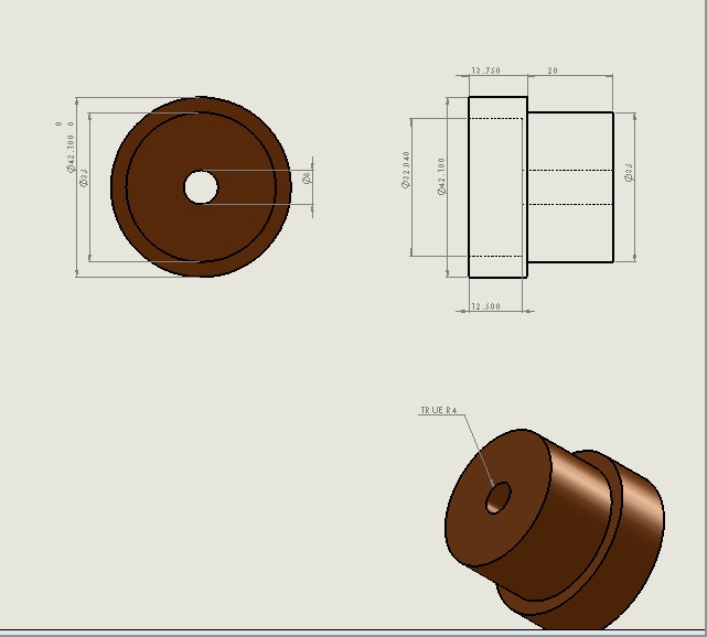
Pilot bearing spacer drawing
Spreadsheet I made for an extra credit assignment in my Thermodynamics class
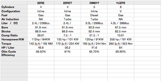
I'll add to this as I get time.
http://dmn.kuulalaakeri.org/vnt-lda/
online manuals
Disk 1: http://www.startekinfo.com/StarTek/o...ram/matrix.htm
Disk 2: http://www.startekinfo.com/StarTek/o...ram/matrix.htm
Pilot bearing spacer drawing
Spreadsheet I made for an extra credit assignment in my Thermodynamics class
I'll add to this as I get time.
Last edited by 89lc; Feb 19, 2013 at 06:51 PM.
Feb 19, 2013 | 07:51 PM
#4

Registered User
Joined: Mar 2012
Posts: 91
Likes: 0
All that info says nothing about the om617s power potential or its reliability, what I called you out on in the first place. And anybody can post crap that they found online or made up with thier computer, physically doing the task on a real engine in more than one vehicle trumps whatever crap you can learn on the web or a class any day. Ask anyone vwho has dealt with me, if I have steered them wrong or giving incorrect advice. Like I said before, you couldn't even successfully get your swap to work after 3 engines and you claim to know what you are doing? You are the only person who couldn't get an om617 swap right. That must mean something. Doesnt look like theclasses have paid off either since you couldnt get your runner to even run right. Oh I was wondering since you posted in another forum that all a person needs to do with the newer merc diesels to get more power is to put some resistors on the computer? Could you elaborate some more or better yet, make up some sweet graph and chart to try to make me believe you know what are talking about? I would love to put some (resistors) on my e class diesel and sprinter like you suggested and get more power.
Last edited by Transplanter; Feb 19, 2013 at 08:02 PM.

Thread
Thread Starter
Forum
Replies
Last Post


