When you click on links to various merchants on this site and make a purchase, this can result in this site earning a commission. Affiliate programs and affiliations include, but are not limited to, the eBay Partner Network.
There is no procedure in the FSM, and I’ve relied on that to say, on this forum, that there is no easy way to test an igniter.
Or is there? How hard can it be?
The coil has 12v with key-on at the (+) lead of the primary. The other primary lead (-) is open, until the igniter pulls it to ground. Current flows through the primary building up a magnetic field. At the right moment, the Igniter “opens” that lead, which stops the current supply and causes the magnetic field to collapse. That collapsing field induces a current in the secondary, which is multiplied by about 1500 to produce the spark.
I started by “testing” the coil. I placed the secondary lead near a good ground. With key-on (so 12v on the coil), I momentarily grounded the “minus” lead. I did get a spark from the secondary lead to ground. But I also got a spark on the primary side! The primary coil is only about 1/2ohm DC resistance, so the current in the coil rapidly ramped to about 20amps, enough to throw a good spark. I didn’t damage my coil, but frankly I suggest you DON’T do what I did. Had I left 12v on a few more milliseconds, I would probably have burned up the coil.
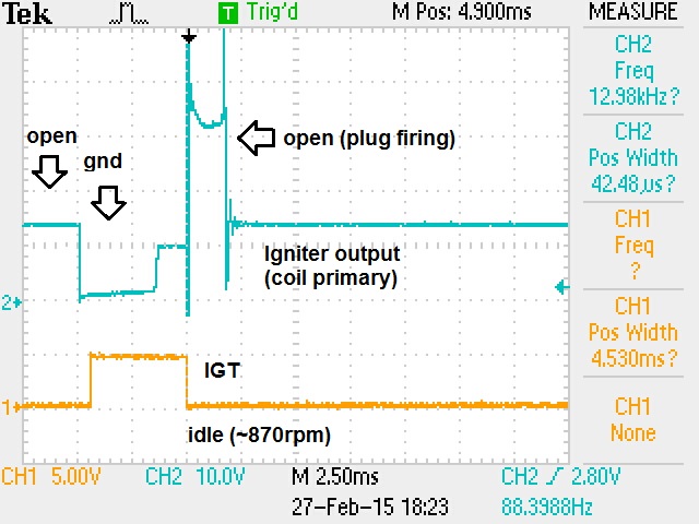
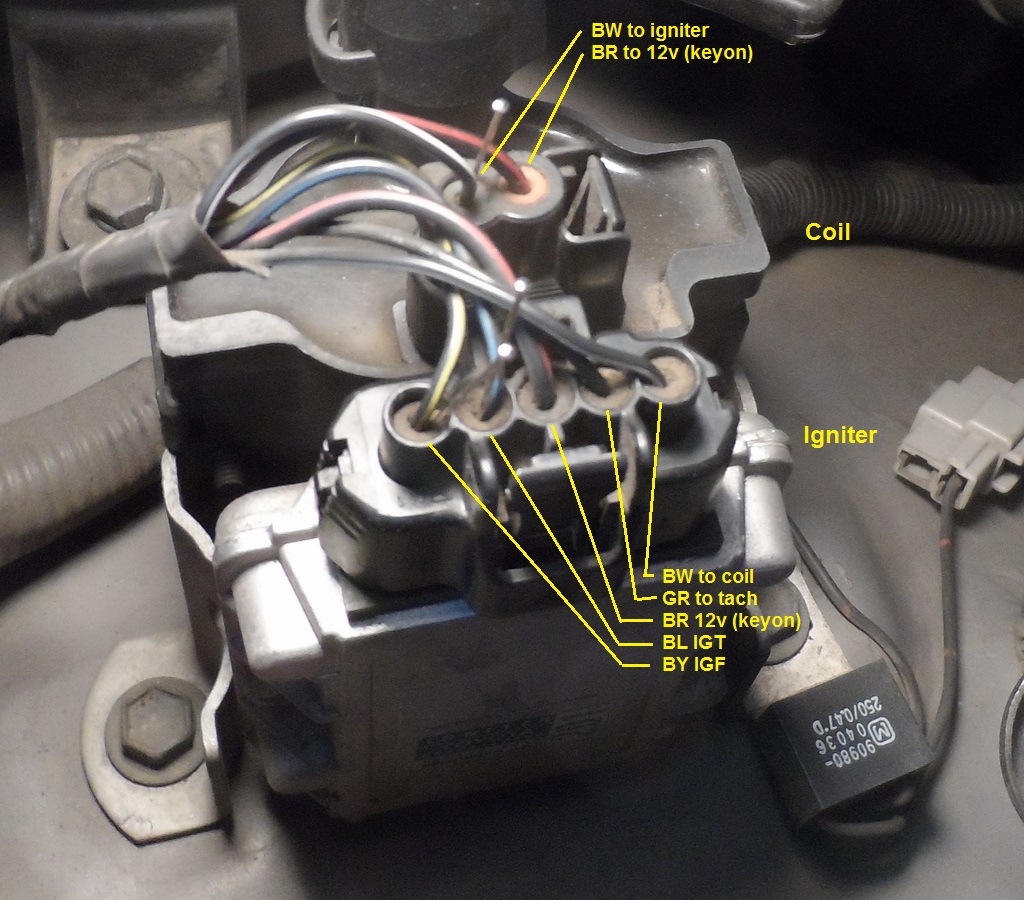
Onto the igniter. The igniter has 6 leads: ground (through the case; it won’t work if not bolted in), 12v, Ignition Trigger (IGT), output to the coil, Ignition Fired (IGF) and the tachometer lead. The IGT comes from the ECU, so it is a pulse about 5v high (RJR surmises it’s 80's era CMOS) with a duty cycle of about 20%. (The pulses get narrower and closer together as engine speed increases.) But you don’t want the ignition pulses to change width with speed, you just want them to get closer together. That’s where the magic of the igniter dwell control http://www.cygnusx1.net/Media/Supra/...taTech/h23.pdf comes into play. In the pictures below, you can see that the “ground time” preceding the ignition is about 3.5ms at idle or at speed, and the actual firing pulse is 1.50-1.75ms, also independent of speed.
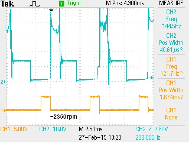
But how does the igniter know when to bring the output to ground? I assumed that the IGT directly controlled that, but you can see that at 2350rpm the output goes to ground about 2ms before the IGT pulse arrives! The igniter is smart enough to figure out when to start charging the coil without input from IGT, and it uses IGT (the falling edge) to determine exactly when to “open” the coil and fire it.
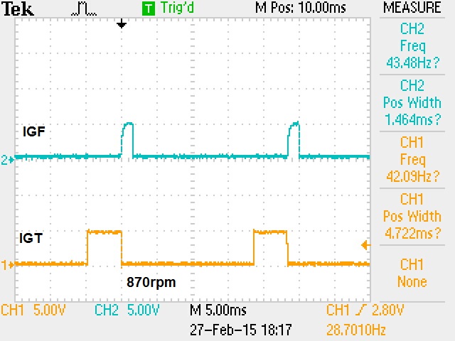
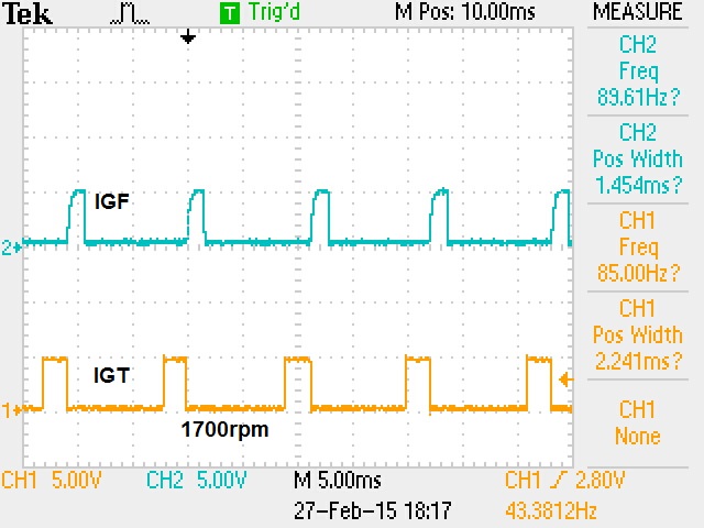
Just for completeness I’ve included some pictures of IGT and IGF. You can see that IGF goes high (again, about 5v) when the plug is firing. (I can’t show all three signals at once; not enough channels.)
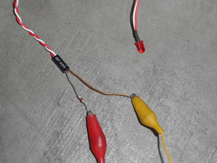
But if you want to test an igniter, you probably don’t have a running engine (or an oscilloscope, but that’s another matter). So I suggest using an LED with a 1K ohm series resistor, like this:
(That LED came of a dead PC. If you need to buy one, just get 12v LED panel indicator, it will have the resistor built in.) Remember that LEDs are polarized, so you probably want to touch your tester to the battery to see which wire is “plus.”
BEFORE you spend some time cranking an engine with no spark, think about what is happening on the fuel side. Even though the plugs aren’t firing, the injectors are, and you’re filling the cylinders and exhaust with unburned gasoline. Raw gasoline will wash the oil off the cylinder walls: not good. And once the engine starts, you’ll be blowing very hot combustion gases into exhaust plumbing filled with gasoline. You could get one heck of an explosion! So you want to interrupt the fuel system while doing this.
Pulling the EFI fuse will stop the fuel pump, but that doesn’t work: the ECU won’t produce IGT. So you need to pull the COR (even though it’s a pain to get to).
You’ll need some way to crank the starter while you’re looking at a not-very-bright LED. If you have a lovely assistant to sit in the driver’s seat, that will work, but if I had such an assistant I could think of better things for them to do. So can you.
You’ll need to back-probe the igniter connections. You could just jam a pin through the insulation (or use a for-that-purpose insulation-piercing probe), but that insulation is there for a reason and I didn’t want to end up with a truck sensitive to rain. I used regular straight pins (dress pins) pushed in around the wire. Even this was tricky; to get the pin in the right place I pulled the plug, and tested each straight pin with an ohmmeter to the “inside” of the plug.
First, the igniter output. That’s tested at the (-) side of the coil. Be very careful that you do not ground this wire while cranking. The manual warns you to never ground the tach output (found at the diagnostic connector) at the risk of destroying the igniter. The tach output and coil input are the same signal. You have been warned.
You are looking for the grounding, so connect the LED plus side to the battery and minus side to the coil. When the truck is running, that terminal is grounding about 40 / second, too fast for you to see. But when you’re cranking the engine (which is what you’re doing to test an igniter), it’s closer to 5/second, which is easily visible. If you see the LED flashing, the coil should fire, so if you have no spark it’s probably the coil.
Next, the igniter input. You’re now looking for a plus-going pulse, so connect the LED between IGT and ground. Again, when you crank the engine, you should see the LED flash about 5/second. If not, you’re not getting an IGT signal. Since a dead igniter could ground-out the IGT signal, disconnect the connector and try again. If still no flashing, I would suspect the wiring before the ECU.
Last, the IGF signal (if everything else works but you don’t have IGF, the ECU throws a code and shuts down the injectors). Nope, your LED won’t work! I tried it, and just the 12ma load of my LED caused the igniter to shut down and stop the engine. As the waveforms above show, you can measure it, but not with an LED.
Last edited by scope103; Mar 28, 2015 at 03:27 PM.
I got bored one day and backprobed some of the igniter wires on my '92 22RE with my oscilloscope...
The blue wire has a 5v square wave. (I assume that's going to ECM)
The green wire has an inverse 12v square wave. (I'm assuming that's from ECM for spark advance)
The grey wire has an 12v pulse.
The yellow wire looks like a coil- pattern.
That would be very slick, but you'd need to get a pair of mating plugs (a "break out box"). Which means you'd need to get the female set off a junk igniter.
And how often would you use it?
I think I would have been better off if I had removed the pins from the plug, so that I could slide back the "weather-packs" and get to the connector from the backside without pushing blindly. I tried; but I was just not talented enough to get the pins out.
I got bored one day and backprobed some of the igniter wires on my '92 22RE with my oscilloscope...
The blue wire has a 5v square wave. (I assume that's going to ECM)
...
The wire pattern (wire colors) is different than my '94? I'm surprised (and disappointed).
The wire pattern (wire colors) is different than my '94? I'm surprised (and disappointed).
Does your igniter "look" like mine?
No, I've got a good old "beer can" coil, and the igniter is different too.
I like your scope better, holding a camera to my scope was ridiculous, I have xoscope for Linux on my PC, but it doesn't handle large voltages.
xoscope uses the microphone input on the soundcard, it actually works pretty good as long as you don't have high voltage. Up to 8 channels! There's a buffer you can build to protect the soundcard on high voltage. I have the components but haven't gotten around to building it yet. And you can't beat free.
Great writeup, scope! Interesting that the tech article I looked at shows the tach output to be an open-collector transistor, which should be totally impervious to being grounded. However, there may also be a (not shown) emitter follower pullup on that line, which of course would blow up in a milli-second if you grounded it.
I have a Hantek two channel scope which works pretty well - I think I paid $80.00 for it. It's basically a USB front end for a laptop. 8-bits at 50MHz sample rate, DC coupled. Comes with a good set of 10:1 10Meg probes which means it will handle several hundred volts with no problem.
If you want a "real" scope that's moderately affordable, I'd check out the ones from Rigol. $329 gets you two channels, 1 Gsample/second, digital storage, USB interface, a real front panel with dedicated control knobs, the whole nine yards. Overkill for automotive, I know, but it's nice working with real tools. Agilent (now Keysight) OEM'd the Rigol unit, spiffed up the front panel a bit, and sold it for twice the price.
Oh, and another tool that's useful for automotive troubleshooting is an old Hewlett-Packard logic probe. You can get them on ebay for $30-40. For automotive use you want the HP545, not the earlier model which requires a 5V supply. The 545 will work from 5V to 18V, so you can just clip it to the battery to power it up. The advantage of these probes over an LED is that they have a pulse stretcher so even hi-speed pulse trains are visible as blinking pulses. Also, they don't load the circuit under test nearly as much. Not as cheap as an LED, but a step up in functionality.
There is no procedure in the FSM, and I�ve relied on that to say, on this forum, that there is no easy way to test an igniter.
Or is there? How hard can it be?
The coil has 12v with key-on at the (+) lead of the primary. The other primary lead (-) is open, until the igniter pulls it to ground. Current flows through the primary building up a magnetic field. At the right moment, the Igniter �opens� that lead, which stops the current supply and causes the magnetic field to collapse. That collapsing field induces a current in the secondary, which is multiplied by about 1500 to produce the spark.
I started by �testing� the coil. I placed the secondary lead near a good ground. With key-on (so 12v on the coil), I momentarily grounded the �minus� lead. I did get a spark from the secondary lead to ground. But I also got a spark on the primary side! The primary coil is only about 1/2ohm DC resistance, so the current in the coil rapidly ramped to about 20amps, enough to throw a good spark. I didn�t damage my coil, but frankly I suggest you DON�T do what I did. Had I left 12v on a few more milliseconds, I would probably have burned up the coil.
Onto the igniter. The igniter has 6 leads: ground (through the case; it won�t work if not bolted in), 12v, Ignition Trigger (IGT), output to the coil, Ignition Fired (IGF) and the tachometer lead. The IGT comes from the ECU, so it is a pulse about 5v high (RJR surmises it�s 80's era CMOS) with a duty cycle of about 20%. (The pulses get narrower and closer together as engine speed increases.) But you don�t want the ignition pulses to change width with speed, you just want them to get closer together. That�s where the magic of the igniter dwell control http://www.cygnusx1.net/Media/Supra/...taTech/h23.pdf comes into play. In the pictures below, you can see that the �ground time� preceding the ignition is about 3.5ms at idle or at speed, and the actual firing pulse is 1.50-1.75ms, also independent of speed.
But how does the igniter know when to bring the output to ground? I assumed that the IGT directly controlled that, but you can see that at 2350rpm the output goes to ground about 2ms before the IGT pulse arrives! The igniter is smart enough to figure out when to start charging the coil without input from IGT, and it uses IGT (the falling edge) to determine exactly when to �open� the coil and fire it.
Just for completeness I�ve included some pictures of IGT and IGF. You can see that IGF goes high (again, about 5v) when the plug is firing. (I can�t show all three signals at once; not enough channels.)
But if you want to test an igniter, you probably don�t have a running engine (or an oscilloscope, but that�s another matter). So I suggest using an LED with a 1K ohm series resistor, like this:
(That LED came of a dead PC. If you need to buy one, just get 12v LED panel indicator, it will have the resistor built in.) Remember that LEDs are polarized, so you probably want to touch your tester to the battery to see which wire is �plus.�
BEFORE you spend some time cranking an engine with no spark, think about what is happening on the fuel side. Even though the plugs aren�t firing, the injectors are, and you�re filling the cylinders and exhaust with unburned gasoline. Raw gasoline will wash the oil off the cylinder walls: not good. And once the engine starts, you�ll be blowing very hot combustion gases into exhaust plumbing filled with gasoline. You could get one heck of an explosion! So you want to interrupt the fuel system while doing this.
Pulling the EFI fuse will stop the fuel pump, but that doesn�t work: the ECU won�t produce IGT. So you need to pull the COR (even though it�s a pain to get to).
You�ll need some way to crank the starter while you�re looking at a not-very-bright LED. If you have a lovely assistant to sit in the driver�s seat, that will work, but if I had such an assistant I could think of better things for them to do. So can you.
You�ll need to back-probe the igniter connections. You could just jam a pin through the insulation (or use a for-that-purpose insulation-piercing probe), but that insulation is there for a reason and I didn�t want to end up with a truck sensitive to rain. I used regular straight pins (dress pins) pushed in around the wire. Even this was tricky; to get the pin in the right place I pulled the plug, and tested each straight pin with an ohmmeter to the �inside� of the plug.
First, the igniter output. That�s tested at the (-) side of the coil. Be very careful that you do not ground this wire while cranking. The manual warns you to never ground the tach output (found at the diagnostic connector) at the risk of destroying the igniter. The tach output and coil input are the same signal. You have been warned.
You are looking for the grounding, so connect the LED plus side to the battery and minus side to the coil. When the truck is running, that terminal is grounding about 40 / second, too fast for you to see. But when you�re cranking the engine (which is what you�re doing to test an igniter), it�s closer to 5/second, which is easily visible. If you see the LED flashing, the coil should fire, so if you have no spark it�s probably the coil.
Next, the igniter input. You�re now looking for a plus-going pulse, so connect the LED between IGT and ground. Again, when you crank the engine, you should see the LED flash about 5/second. If not, you�re not getting an IGT signal. Since a dead igniter could ground-out the IGT signal, disconnect the connector and try again. If still no flashing, I would suspect the wiring before the ECU.
Last, the IGF signal (if everything else works but you don�t have IGF, the ECU throws a code and shuts down the injectors). Nope, your LED won�t work! I tried it, and just the 12ma load of my LED caused the igniter to shut down and stop the engine. As the waveforms above show, you can measure it, but not with an LED.
This thread came so close in helping me diagnose my 93 Toyota pickup igniter because of the picture of the igniter with the labels on the wires. Yet my igniter has 6 wires and Im not going to risk damaging it by guessing where the one extra wire connects.

 Mar 28, 2015 | 03:08 PM