
persistent code 2 checked AFM and wiring - ECU fault?
 Jan 13, 2013 | 06:38 PM
#1

Thread Starter
Registered User
Joined: Jan 2013
Posts: 3
Likes: 0
From: Nicaragua
persistent code 2 checked AFM and wiring - ECU fault?
Actually its a 22RE in a 1985 Celica with 89661-35010 ECU but as far as i found out its compatible with the 89661-35020 and 89661-35070 used in the 86-87 trucks. That is why i post here and hope to get advise on this forum.
Bought it as a project with the engine in bad shape and not starting. Meanwhile it starts, but runs badly and the check engine light is on.
ECU gives code 2 (AFM). After clearing the code and connecting the battery the code shows up again - immediately without cranking. Checked AFM resistance and voltages on the ECU connector and everything is within spec. FSM points to ECU fault.
Did anyone experience this error, any advice before buying a ECU? Or anything to repair inside the ECU?
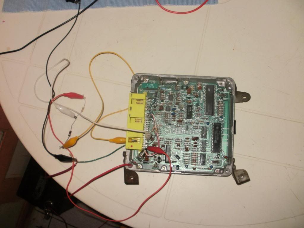
UPDATE: Just bench-tested the ECU (that is nothing described in the FSM) and with some suitable resistors connected to simulate the AFM, no more error code 2! First time its gone. To remember: the AFM and wiring tested ok with the procedure described in the FSM. Tomorrow i will look into the AFM and post results. That is the test setup for the ECU itself:
Bought it as a project with the engine in bad shape and not starting. Meanwhile it starts, but runs badly and the check engine light is on.
ECU gives code 2 (AFM). After clearing the code and connecting the battery the code shows up again - immediately without cranking. Checked AFM resistance and voltages on the ECU connector and everything is within spec. FSM points to ECU fault.
Did anyone experience this error, any advice before buying a ECU? Or anything to repair inside the ECU?
UPDATE: Just bench-tested the ECU (that is nothing described in the FSM) and with some suitable resistors connected to simulate the AFM, no more error code 2! First time its gone. To remember: the AFM and wiring tested ok with the procedure described in the FSM. Tomorrow i will look into the AFM and post results. That is the test setup for the ECU itself:
Last edited by hjj; Jan 13, 2013 at 09:57 PM. Reason: Update
Jan 14, 2013 | 04:20 PM
#2

FSM only starts listing diagnostic codes at 12. Can you provide/post the rest?
Try moving that test rig to the car harness and see if it still works, maybe frayed wiring?
Try connecting at the chip instead of the connector, trace maybe blown between the two.
You did both the ECU and AFM tests from the manual right?
Can't really make out the wiring of the test rig, more and better pictures maybe schematics
Jan 15, 2013 | 08:16 PM
#3
Thread Starter
Registered User
Joined: Jan 2013
Posts: 3
Likes: 0
From: Nicaragua
Solved: included more tests and description of AFM operation
Finally got the engine running. As i learned a lot about how the AFM works i will include that information here (turned out to be quite long a text...).
Following the tests described in the FSM everything checked out fine so the only option left was ECU fault. I already wanted to buy a new one but decided to keep trying. Actually the problem was inside the AFM and i could repair it at nearly no cost.
If you have access to a cheap replacement it might be easier to just swap the AFM but for the curious i will describe the results of my investigations and hopefully it will be useful for somebody.
Detailed operation of the AFM (skip if only interested in testing � read below)
A very good description of the AFM can be found at http://www.4crawler.com/4x4/CheapTricks/AFM/index.shtml i will asume you have already consulted the link for understanding what follows. This site mentions the resistance terminals VB and VC, a test not mentioned in the FSM. Its value should be around 100 Ohm. I measured 182 and after trying a little bit i found out that was the problem. But let�s look deeper into the internal operation. By the way, the following refers to early AFMs might be they changed at some point.
Here is a quick sketch of the internal circuit, only showing the parts relevant for air flow measurement. Not shown are the fuel pump switch and temperature sensor:
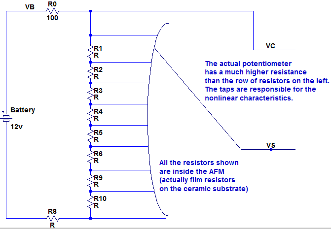 Obviously the battery is not connected directly but via fuse and the ECU relay. The actual potentiometer is connected to battery voltage (VB) and ground (E2), but not directly: there are resistors in between. There are two intermediate connection: The first (VC) is after the resistor coming from VB. The second (VS) is the wiper of the potentiometer.
To make things clear: The test procedure in the FSM specifies resistances but in normal operation what counts are the voltages at terminals VC and VS (resulting from the various resistances connected in series). The wiper of the potentiometer is connected to the flap door so as air flow changes, the wiper moves along the potentiometer and picks up the corresponding voltage value along the potentiometer's track. As there are fixed resistors in series with the potentiometer its voltage reading will not change from 0 to full battery voltage, but has some limited range in between.
Now why is there VC? VC gives the maximum voltage of the potentiometer (at the top limit of the wiper). That is required as battery voltage is not constant and to limit the effects of the wire and contact resistance from AFM to the ECU. Actually the ECU will have to compute the relation VS/VC. (that is all hidden inside the ECU, but obvious for someone with a background in electronics).
There is one more detail: As the flap door opens, the angle of the wiper changes and in a simple potentiometer the voltage changes proportionally to the wiper angle. But not here. The resistance of the actual potentiometer track is much higher as a chain of resistors are connected in parallel via taps along the track. Actually its an exponential relation between wiper angle and voltage. That is why you observe a wave pattern in the resistance test between E2 and VS.
Testing the AFM
In my case i followed the tests in the FSM and all checked out ok, but the ECU nevertheless reported a faulty AFM.
So after doing some tests I found out that the resistance between VB and VC must be within certain limits otherwise the ECU considers it as faulty (The FSM does not mention this value). In the link from 4crawler.com he measured 100 Ohm, my one had 182 Ohm and did not work. So i tried out different values and found out it works with values in between 70 and 150 Ohm (you can do that without opening it by leaving VB terminal open and connecting battery voltage via the resistor to VC, and all that values are for my particular unit).
Repair
The problem finally was that someone had opened the plastic cover and did not seal it properly, water came in and corroded the resistor between VB and VC causing a higher than normal value. What I did was disable the original resistor and solder a 100 Ohm resistor between terminals VB and VC, closed the box and sealed it with RTV.
Characteristics of the VS signal
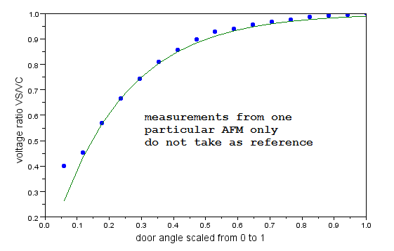
I wanted a better understanding of the VS voltage so i connected the battery between VB and E2 and measured the voltage at different wiper angles. Angles are in one tooth increments of the wheel inside (hold the wiper in place with a small screwdriver positioned in the tooth). Also recorded the voltage of VC. As battery voltage is not constant, i give the values divided by VC:
0.4012638 door completely closed
0.4533965
0.5687204
0.6666667
0.7424961
0.8104265 values are VS/VC
0.8562401 equally spaced angles
0.8973144 from closed to open
0.9289100
0.9399684
0.9573460
0.9668246
0.9763033
0.9873618
0.9921011
0.9952607
1. door fully open
These are just measurements for one particular AFM that has been tempered with before, and different units or types may give different readings. So do not take that as reference values for your unit. But looking at the graph it looks quite reasonable (actually close to a exponential function � green line):
Following the tests described in the FSM everything checked out fine so the only option left was ECU fault. I already wanted to buy a new one but decided to keep trying. Actually the problem was inside the AFM and i could repair it at nearly no cost.
If you have access to a cheap replacement it might be easier to just swap the AFM but for the curious i will describe the results of my investigations and hopefully it will be useful for somebody.
Detailed operation of the AFM (skip if only interested in testing � read below)
A very good description of the AFM can be found at http://www.4crawler.com/4x4/CheapTricks/AFM/index.shtml i will asume you have already consulted the link for understanding what follows. This site mentions the resistance terminals VB and VC, a test not mentioned in the FSM. Its value should be around 100 Ohm. I measured 182 and after trying a little bit i found out that was the problem. But let�s look deeper into the internal operation. By the way, the following refers to early AFMs might be they changed at some point.
Here is a quick sketch of the internal circuit, only showing the parts relevant for air flow measurement. Not shown are the fuel pump switch and temperature sensor:
Obviously the battery is not connected directly but via fuse and the ECU relay. The actual potentiometer is connected to battery voltage (VB) and ground (E2), but not directly: there are resistors in between. There are two intermediate connection: The first (VC) is after the resistor coming from VB. The second (VS) is the wiper of the potentiometer. To make things clear: The test procedure in the FSM specifies resistances but in normal operation what counts are the voltages at terminals VC and VS (resulting from the various resistances connected in series). The wiper of the potentiometer is connected to the flap door so as air flow changes, the wiper moves along the potentiometer and picks up the corresponding voltage value along the potentiometer's track. As there are fixed resistors in series with the potentiometer its voltage reading will not change from 0 to full battery voltage, but has some limited range in between.
Now why is there VC? VC gives the maximum voltage of the potentiometer (at the top limit of the wiper). That is required as battery voltage is not constant and to limit the effects of the wire and contact resistance from AFM to the ECU. Actually the ECU will have to compute the relation VS/VC. (that is all hidden inside the ECU, but obvious for someone with a background in electronics).
There is one more detail: As the flap door opens, the angle of the wiper changes and in a simple potentiometer the voltage changes proportionally to the wiper angle. But not here. The resistance of the actual potentiometer track is much higher as a chain of resistors are connected in parallel via taps along the track. Actually its an exponential relation between wiper angle and voltage. That is why you observe a wave pattern in the resistance test between E2 and VS.
Testing the AFM
In my case i followed the tests in the FSM and all checked out ok, but the ECU nevertheless reported a faulty AFM.
So after doing some tests I found out that the resistance between VB and VC must be within certain limits otherwise the ECU considers it as faulty (The FSM does not mention this value). In the link from 4crawler.com he measured 100 Ohm, my one had 182 Ohm and did not work. So i tried out different values and found out it works with values in between 70 and 150 Ohm (you can do that without opening it by leaving VB terminal open and connecting battery voltage via the resistor to VC, and all that values are for my particular unit).
Repair
The problem finally was that someone had opened the plastic cover and did not seal it properly, water came in and corroded the resistor between VB and VC causing a higher than normal value. What I did was disable the original resistor and solder a 100 Ohm resistor between terminals VB and VC, closed the box and sealed it with RTV.
Characteristics of the VS signal
I wanted a better understanding of the VS voltage so i connected the battery between VB and E2 and measured the voltage at different wiper angles. Angles are in one tooth increments of the wheel inside (hold the wiper in place with a small screwdriver positioned in the tooth). Also recorded the voltage of VC. As battery voltage is not constant, i give the values divided by VC:
0.4012638 door completely closed
0.4533965
0.5687204
0.6666667
0.7424961
0.8104265 values are VS/VC
0.8562401 equally spaced angles
0.8973144 from closed to open
0.9289100
0.9399684
0.9573460
0.9668246
0.9763033
0.9873618
0.9921011
0.9952607
1. door fully open
These are just measurements for one particular AFM that has been tempered with before, and different units or types may give different readings. So do not take that as reference values for your unit. But looking at the graph it looks quite reasonable (actually close to a exponential function � green line):

Thread
Thread Starter
Forum
Replies
Last Post
sandyota
84-85 Trucks & 4Runners
18
Feb 4, 2021 11:16 AM


