
Need help with 22RE wiring after 5-speed swap
 06-02-2014, 11:07 AM
#1
Registered User
Thread Starter
Join Date: Dec 2012
Posts: 98
Likes: 0
Received 0 Likes
on
0 Posts
Need help with 22RE wiring after 5-speed swap
My rig was born as an 88 4runner with 22RE and A340H and I have decided to rebuild the engine and swap in a 5-speed at the same time.
I bought a running donor pickup - 88 22RE with a W56 5-speed tranny.
I decided to rebuild the engine in the truck to minimize down time on the 4runner. I kept the manual wiring harness on the engine since that would mate up nicely to the W56. I should point out that both vehicles HAVE THE SAME ECU, which I found contrary to what other people have said, but hey... it should make the swap simpler, right? Well, maybe not...
First of all, let me tell you that I am not very good at reading electrical schematics. I have stared at the FSM and read every 5-speed swap thread I could find for weeks and I could really use some suggestions from you folks!
Everything is installed now and looking the cluster of connectors in the right side pass kick-panel behind the ECU, there is one connector coming from the manual engine harness that has nowhere to plug in. There is also a connector coming from the chassis automatic transmission ECU that is also homeless.
The only way I could get the engine to turn over is to connect ST1 (Black with White stripe at steering column) directly to the small spade-terminal on the bottom of the starter. There is no starter relay under the hood for the Automatic. I assume that the neutral start switch performed this function on the auto. I do have the starter relay from the donor truck if I need to wire it in. The engine did crank and run ok, but I was afraid I was bypassing something in the ECU and did not run it long. The automatic ECU was unplugged.
What all am I missing here? Where does the COR enter into the picture? I really do not want to dismantle my dash to trace ST1 over to the ECU. I am OK with by-passing the clutch-start switch for now, but plan to add it and the clutch cancel switch later.
I will post pics when I get home of the connectors.
Thanks in advance for taking the time to help out a brother!
 06-02-2014, 12:27 PM
#2
Registered User
Thread Starter
Join Date: Dec 2012
Posts: 98
Likes: 0
Received 0 Likes
on
0 Posts
I should also point out that I have no back-up lights and the 4WD indicator doesn't work. I guess I am going to have to make-up an adapter to mate these two orphaned connectors.
06-02-2014, 06:39 PM
#3
Registered User
Thread Starter
Join Date: Dec 2012
Posts: 98
Likes: 0
Received 0 Likes
on
0 Posts

The connector from the engine harness is the small one on the left, the chassis connector is on the right.
I thought I had it figured out tonight, but when I cranked it, the starter dragged until I turned the switch off. I am going to fing burn something out just randomly trying stuff.
I think the difference with my swap than everyone else's is that I used the manual engine wiring harness. If I had used the auto it would be all good. I could figure it out. I was just trying not to splice up the tranny connectors. That's what I get for thinking ahead.
06-03-2014, 04:59 AM
#4
Registered User

Join Date: Jul 2012
Location: Central MA
Posts: 234
Likes: 0
Received 0 Likes
on
0 Posts
Your problem is that you don't have a starter relay in the circuit. As you mentioned it is specific to the manual trans equipped trucks. In the auto trucks the neutral safety switch performs this function.
The clutch switch OR the clutch override switch provides ground to the coil of the starter relay. This actuates the relay and allows the 12V from ST1 to pass to the starter.
You will need to wire it in.
The clutch switch OR the clutch override switch provides ground to the coil of the starter relay. This actuates the relay and allows the 12V from ST1 to pass to the starter.
You will need to wire it in.
06-03-2014, 05:09 AM
#5
Registered User
Join Date: Jul 2012
Location: Central MA
Posts: 234
Likes: 0
Received 0 Likes
on
0 Posts
I should also mention that the stater relay also sends 12V to the cold start injector while the truck is starting and it sends a 12V signal to the ECU as well. So its pretty important.
06-03-2014, 07:13 AM
#6
Registered User
Thread Starter
Join Date: Dec 2012
Posts: 98
Likes: 0
Received 0 Likes
on
0 Posts
Thanks for the help Admiral
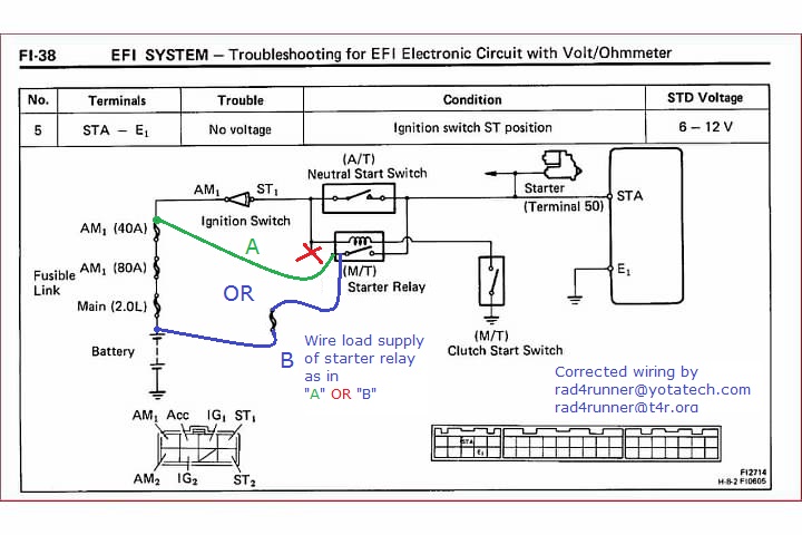
OK. I think I have a plan now. I found this in the EFI section of the FSM.

Option 1- I can add the clutch switch, clutch cancel switch and Starter Relay to the circuit and run new trigger wire to the starter and check to make sure that STA on the ECU is getting 12V. IF it is not, branch off from the trigger wire directly to STA.
Option 2- (Safety concerns aside) I can return to 1980 for a while and not add any switches or relays, tap into ST1 at the steering column (or preferably at wiring harness close to ECU) and run a trigger wire directly to the starter. Make sure that STA on the ECU is getting 12V+. IF it is not, branch off from the trigger wire directly to STA.
I am hoping that getting 12v+ to STA will trigger cold start injection and provide all the other miscellaneous magic that the engine needs from the ECU.
Question 1 - If I go with option 2, am I correct in assuming that you don't need a relay if you are eliminating the clutch switches? It looks like it's just a switch in the Auto tranny (no relay there). Any harm done to the ignition switch?
Question 2 - Is the 12v+ to STA a momentary trigger or is it continuous?
06-03-2014, 07:38 AM
#7
Registered User
Join Date: Jul 2012
Location: Central MA
Posts: 234
Likes: 0
Received 0 Likes
on
0 Posts
Call me crazy....but why don't you just install an OEM starter relay? I'm willing to bet you have an empty spot for it in the fuse block.
It wouldn't surprise me if the wires are already there. If not, it would be pretty simple to re-wire per the factory.
It wouldn't surprise me if the wires are already there. If not, it would be pretty simple to re-wire per the factory.
Trending Topics
06-03-2014, 07:45 AM
#8
Yes, save your starter relay, and wire it like the manual.
Note that stock starter relay wiring for 86-88 shown on Toyota FSM wiring is crap. Here's how it should be wired.
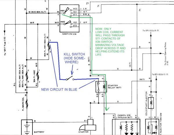
Note that stock starter relay wiring for 86-88 shown on Toyota FSM wiring is crap. Here's how it should be wired.
Last edited by RAD4Runner; 06-03-2014 at 07:48 AM.
06-03-2014, 09:45 AM
#10
If you would rather not dig into your fuse block to connect load supply side of starter solenoid (blue in above schematic) to 40-amp FL, connect it to battery positive through a fuse.
Pls see explanation on my signature.
ECU wiring in above is correct. However, that schematic above should be corrected to this:
Kudos on taking a challenging swap

Last edited by RAD4Runner; 06-03-2014 at 10:04 AM.

 06-03-2014, 10:06 AM
#12
Now power to starter solenoid does not have to run back to the cabin, to the ignition switch and back to engine compartment (about 8 feet of wire), It can simply go from fuse block to kill switch, to starter relay in engine compartment, to solenoid... maybe a couple of feet of wire.
Last edited by RAD4Runner; 06-03-2014 at 10:10 AM.
06-03-2014, 10:13 AM
#13
Registered User
Thread Starter
Join Date: Dec 2012
Posts: 98
Likes: 0
Received 0 Likes
on
0 Posts
Thanks RAD. Read your last post after I put up my last post
Wow - 12 amps! Definitely going with relay! If I can make it look nice and factory, I'll try to dig into the fuse block.
If I tap into the correct wires as shown in my last post, shouldn't the EFI and cold start be happy since they are still connected to STA? I checked continuity between STA at ECU and the cold start injector with ignition off and got continuity.
06-03-2014, 10:22 AM
#14
Registered User
Thread Starter
Join Date: Dec 2012
Posts: 98
Likes: 0
Received 0 Likes
on
0 Posts
I should also mention to other electrically challenged people that may find themselves in this situation - the 2 black wires coming from the factory starter relay are not the same. B#2 should read resistance across B-R and no connection to B-W. B#1 should read no resistance to any other wires coming out of the relay.
06-03-2014, 01:59 PM
#15
Thanks RAD. Read your last post after I put up my last post
Wow - 12 amps! Definitely going with relay! If I can make it look nice and factory, I'll try to dig into the fuse block.
If I tap into the correct wires as shown in my last post, shouldn't the EFI and cold start be happy since they are still connected to STA? I checked continuity between STA at ECU and the cold start injector with ignition off and got continuity.
Wow - 12 amps! Definitely going with relay! If I can make it look nice and factory, I'll try to dig into the fuse block.
If I tap into the correct wires as shown in my last post, shouldn't the EFI and cold start be happy since they are still connected to STA? I checked continuity between STA at ECU and the cold start injector with ignition off and got continuity.
Just double-check. According to your EFI schematic and mine above
Contact output pin of starter relay supplies STA, starter solenoid and cold-start injector
I should also mention to other electrically challenged people that may find themselves in this situation - the 2 black wires coming from the factory starter relay are not the same. B#2 should read resistance across B-R and no connection to B-W. B#1 should read no resistance to any other wires coming out of the relay.
 06-03-2014, 02:23 PM
#16
Super Moderator
Staff
iTrader: (1)
Join Date: Aug 2008
Location: Anderson Missouri
Posts: 11,788
Likes: 0
Received 21 Likes
on
19 Posts
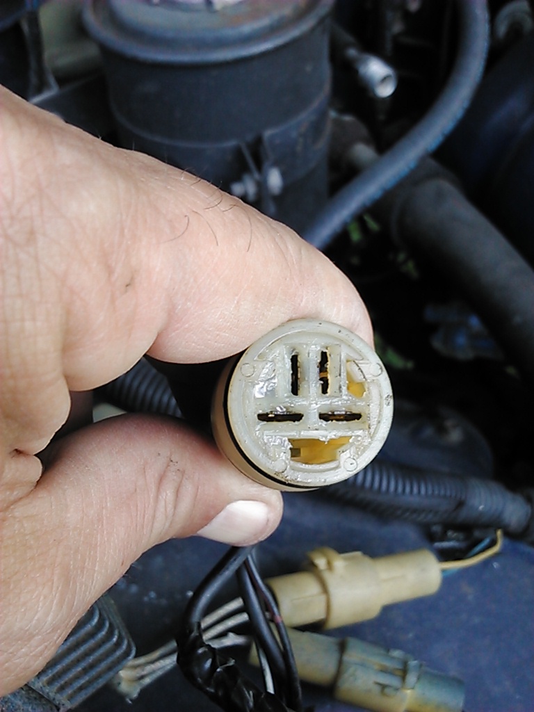
I did Rays upgrade and here is a picture how I did mine. Solved my clicking issues and I changed the contacts in the starter and cleaned the starter relay contacts as well. With another starter relay, I would suggest cleaning the contacts while you have it out.
Copied
I did Rays Starter Upgrade. Last week Misty had mine at the store and it would not start for her. I showed up and jumped in and it started right up. I asked her if she was turning the key, had the key in the ignition, and even had the keys, lol. It has done this to me before as well so I was just teasing her. I have replaced the Solenoid Contacts and cleaned the Starter Relay Contacts as well and it still will just click every once in awhile. For me I can usually start tapping on things and getting it going. Misty doesnt quite understand how to get around something like that and the clicking issue is frustrating.
I got Ray on the phone and he stepped me thru on doing the upgrade and what all was happening. He did a great job on explaining how the electric flowed that I could understand it. Thanks Ray for your help. I had just gotten anotherrr new phone as I dropped my other new phone and broke it. He had to contend with me trying to learn all of that as well. One time even trying to find the key pad to call back.
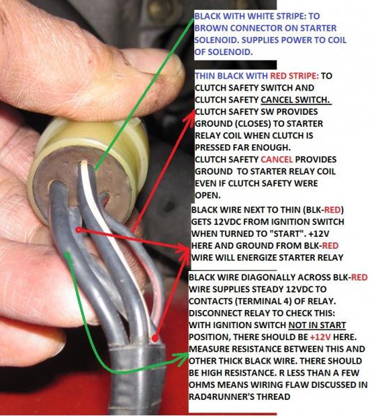
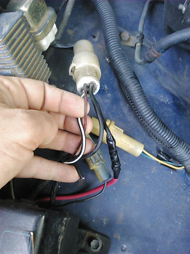
If you look at the plug with eyes, mustache and a smile, the one you need to cut is the right side of the mustache as you are looking at it, hehe
What I am trying to show here is the thinnest little black wire with the red stripe is on the left. The wire on the right is the one you want to cut which is diagonally across from the red stripe wire. Going from Left, Top, Right and Bottom, it is the Right one. The wire that I cut and is where my pinky is going to get wrapped back up into the wiring harness and will not be used again.
I eventually want to run a kill switch inside the cab and to do the AFM and Battery Swap. I also have an 82 Supra AFM that I want to install when I do all of that. I feel this will fix the click only issue and Thanks Ray for taking the time to step me thru it.
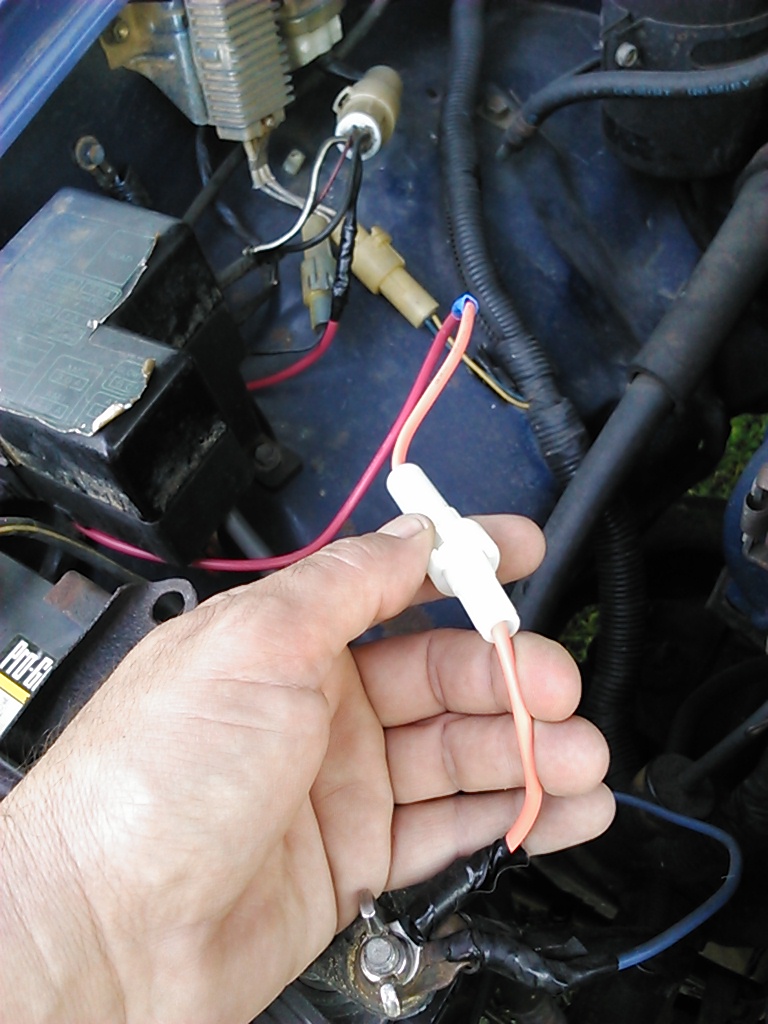
To try and show how I have it and how it is routed, it comes off of the batttery with a 30 Amp Fuse connector, along fender well to the Starter Relay Plug. I have left the wires loose just for explanation purposes but did route it tighter and cleaner.
Copied
I did Rays Starter Upgrade. Last week Misty had mine at the store and it would not start for her. I showed up and jumped in and it started right up. I asked her if she was turning the key, had the key in the ignition, and even had the keys, lol. It has done this to me before as well so I was just teasing her. I have replaced the Solenoid Contacts and cleaned the Starter Relay Contacts as well and it still will just click every once in awhile. For me I can usually start tapping on things and getting it going. Misty doesnt quite understand how to get around something like that and the clicking issue is frustrating.
I got Ray on the phone and he stepped me thru on doing the upgrade and what all was happening. He did a great job on explaining how the electric flowed that I could understand it. Thanks Ray for your help. I had just gotten anotherrr new phone as I dropped my other new phone and broke it. He had to contend with me trying to learn all of that as well. One time even trying to find the key pad to call back.
If you look at the plug with eyes, mustache and a smile, the one you need to cut is the right side of the mustache as you are looking at it, hehe

What I am trying to show here is the thinnest little black wire with the red stripe is on the left. The wire on the right is the one you want to cut which is diagonally across from the red stripe wire. Going from Left, Top, Right and Bottom, it is the Right one. The wire that I cut and is where my pinky is going to get wrapped back up into the wiring harness and will not be used again.
I eventually want to run a kill switch inside the cab and to do the AFM and Battery Swap. I also have an 82 Supra AFM that I want to install when I do all of that. I feel this will fix the click only issue and Thanks Ray for taking the time to step me thru it.

To try and show how I have it and how it is routed, it comes off of the batttery with a 30 Amp Fuse connector, along fender well to the Starter Relay Plug. I have left the wires loose just for explanation purposes but did route it tighter and cleaner.
 06-03-2014, 02:26 PM
#17
Super Moderator
Staff
iTrader: (1)
Join Date: Aug 2008
Location: Anderson Missouri
Posts: 11,788
Likes: 0
Received 21 Likes
on
19 Posts
I have changed out several harnesses. I tried to create a thread if you want to try and install the correct one. https://www.yotatech.com/forums/f116...4-88-a-278925/ If you are interested in swapping harnesses, I can put up some information on the differences between a truck and 4Runner. About the only difference is that the tail light harness runs inside the body where a truck goes to the passenger frame rail.
06-04-2014, 04:58 AM
#18
Registered User
Thread Starter
Join Date: Dec 2012
Posts: 98
Likes: 0
Received 0 Likes
on
0 Posts
Great visual aids guys, Thanks!..... I like pictures!
Did the mod last night and all is good. Drove her to work this morning!
I hooked mine up a little bit differently though. The B-W (black with white stripe) wire coming from the relay, instead of going directly to the starter, I hooked this up to the solid black wire in the kick panel connector (see post 11). I know it's a few more feet of wire, but I wanted to make sure that the cold start injector and STA on the ECU also got energized. Also, that's one more connection to make inside the cab (more protected).
Anybody see a downside to this?
edit - I wish I had read your threads explaining the starter system a little closer. Do you think I am OK with a 14 gau. wire going from relay to kick panel STA (maybe 3 feet) and then out thru original wiring to the starter? I may leave what I have to energize STA and add another 12 gau. wire going straight to the starter.
Last edited by JodyR; 06-04-2014 at 07:22 AM.
06-04-2014, 06:14 AM
#19
Registered User
Thread Starter
Join Date: Dec 2012
Posts: 98
Likes: 0
Received 0 Likes
on
0 Posts
That's a great step-by-step thread Terry. Nice to know exactly where all the fasteners are and how to dismantle the dash correctly. I appreciate the offer, but I don't think I am going to switch out or create a new harness at this time. If I can figure out the reverse switch and 4WD indicator light, I will be golden.
I will post up the connections when I get them figured out
When you say clean the starter relay contacts, are you referring to the wiring connections on the plug? I see also that you added a little dielectric grease there. Love that stuff.
I will post up the connections when I get them figured out
When you say clean the starter relay contacts, are you referring to the wiring connections on the plug? I see also that you added a little dielectric grease there. Love that stuff.
06-04-2014, 06:31 AM
#20
Registered User
Thread Starter
Join Date: Dec 2012
Posts: 98
Likes: 0
Received 0 Likes
on
0 Posts
RAD - I thought about at putting an additional 40A fuse in the spare socket next to the 80A fuse, but thought that was too much work. Instead, I tapped into the white-red wire under the fuse block coming off of the fused leg of the 40A. I un-taped the harness and stripped a 1/2" section of the insulation from the about 4-6 inches away from the fuse block. I wrapped the black relay wire around that 3 or 4 turns and soldered that up using paste flux. I then wrapped it all up using good thick 3M super 33 tape.
I really hate tapping into wires. It is painful. No really good clean way to do it.
I really hate tapping into wires. It is painful. No really good clean way to do it.


