
Help! Wiring Issue!
 Oct 27, 2011 | 07:10 PM
#21
Registered User
Joined: Oct 2011
Posts: 278
Likes: 1
From: visalia, ca
ok sent email. . . . . .i sent diagnostic codes which will do you no good but if you find your condition, and look to the very right column for that condition, it will tell you which pages to look at in the troubleshoot section. i know 89 had some major changes. . . . .hopefully your wiring is about the same as mine
Oct 27, 2011 | 07:13 PM
#23

Thread Starter
Registered User
Joined: Aug 2011
Posts: 38
Likes: 0
nope, honda_wern@yahoo.com its an underscore.
Oct 27, 2011 | 07:46 PM
#24
Registered User
Joined: Dec 2007
Posts: 420
Likes: 7
From: Missoula, MT
It looks like you should have the ref voltage on one side of the coolant temp sensor (water thermo sensor) and a sensor ground on the other. I haven't been able to find any voltages for testing either. Only resistance readings for the sensors themselves. One of the wires (the brown and black) is also connected to the AFM and TPMS among others, so it could be at one of the other sensors that you are actually having a problem.

Oct 27, 2011 | 07:57 PM
#25
Thread Starter
Registered User
Joined: Aug 2011
Posts: 38
Likes: 0
I snipped the brown and black wire at the CTS and the AFM and also the other end at the ecu which was THW and E2. I then ran a jumper from CTS to AFM to ECU. I had 5v at both E2 and THW coming out of the ECU?
Oct 28, 2011 | 04:37 AM
#27
Registered User
Joined: Dec 2007
Posts: 420
Likes: 7
From: Missoula, MT
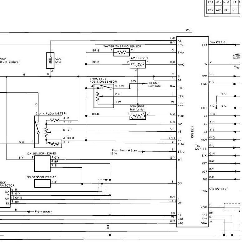
By the sound of it, I'd say that you should check the wires at the AFM to make sure somebody didn't mix up the wires there. According to the diagram below and a connector view I have, with the AFM plugged in you should see wire colors in the following order from left to right:
white/black, green, brown/black, black, blue/red, yellow/blue, yellow
Make sure to check further up the harness for new tape indicating that somebody's been in there possibly splicing wires.
white/black, green, brown/black, black, blue/red, yellow/blue, yellow
Make sure to check further up the harness for new tape indicating that somebody's been in there possibly splicing wires.
Oct 28, 2011 | 05:48 AM
#28
Thread Starter
Registered User
Joined: Aug 2011
Posts: 38
Likes: 0
I have removed to loom from the afm connector back to the main harness and found nothing. I am becoming more concerned about the no check engine light issue. Anyone know anything about the cel circut. What tells the light to come on. It would be much easier to Chase if I could pull codes
Oct 30, 2011 | 08:23 AM
#30

Registered User
Joined: Oct 2005
Posts: 578
Likes: 2
From: New Brunswick, Canada
I don't know if I would put much faith in the voltage measurements that you made in your initial post.
You were obviously measuring from the Brown/Black to ground [battery (-)] and the green wire to ground [battery (-)]when you measured 12 and 5 volts respectively. Some people call the Brown/Black (E2) a sensor ground, but from the wiring diagrams it has no reference to actual ground [battery (-)]. Refering to at as sensor negative is probably a more accurate title.
The measurements you want to consider are the voltages at the ECU when the engine is operating or the ignition switch is on. If you assume that the resistance of the wires is minimal then the voltage drop across the wires is a non factor, so voltage measurements across the various sensors should be very close to the measurements at the ECU.
You are dealing with an 88, I don't have a wiring diagram book for that year, but I do have 86 and 89. My 86 book says that the voltage measurement between E2 and THW should be 0.5-2.5v with the ignition switch on and the coolant temp is at 80 deg. C or 176deg F., but my 89 book says that the voltage should be 0.1-1.0v under the same conditions. I'm thinking that the 89 values are the probably similiar to your 88. The 89 has 3 plugs at the ECU, 14p (f), 18p (g) and 10p (h) My wiring diagram book references these plugs as f,g and h. You may have to reference the wiring diagram that nv4Runner posted for you. Also a straightened paper clip works pretty well for a voltmeter connection through the back of a plug.
So here are the measurements for the 89:
Voltage at ECU Connectors
f8-h7 B+ - E1 10-14v Ignition sw. on.
f2-h7 Batt - E1 10-14 v always
g12-g14 VCC - E2 4-6 v Ignition sw. on
g6-g14 IDL - E2 8-14 v Ignition sw. on and Throttle valve open
g11-g14 VTA - E2 0.1-1.0 v Ignition sw. on and throttle valve fully closed
3-5 v Ignition sw. on and throttle valve fully open
h8-h7 IGT - E1 0.7-1.0v cranking or idling
h3-h7 STA - E1 6-12 v Ignition sw. in start position
h4-h5 #10 - E01 h9-h10 #20 - E02 10-14 v Ignition sw. on
g8-h7 w (check engine light) - E1 10-14 v no trouble codes and engine running
f4-g14 VS - E2 0.5-2.5 v Ignition Sw. on and air intake temp. 20 deg C / 68 deg F
5-10 v Ignition sw. on and measuring plate fully open
2-8 v idling
f3-g14 THA - E2 1-3 v Ignition sw. on and air intake temp 20 deg C / 68 deg F
g10-g14 THW - E2 0.1-1.0 v Ignition sw. on and coolant temp 80 deg C / 176 deg F
f5-g14 VC - E2 6-10 v Ignition Sw. on
f9-g14 STP - E2 10-14 v stop light sw. on
Resistance at ECU Wiring Connectors (connectors disconnected from ECU)
g6-g14 IDL - E2 Infinity throttle valve open, 0-100 ohms throttle valve fully closed
g11-g14 VTA - E2 3.3-10 Kilo-ohms throttle valve fully open
0.2-0.8 Kilo-ohms throttle valve fully closed
g12-g14 VCC - E2 3-7 Kilo-ohms
f3-g14 THA - E2 2-3 Kilo-ohms intake air temp 20 deg C / 68 deg F
g10-g14 THW - E2 0.2-0,4 Kilo-ohms coolant temp 80 deg C / 176 deg F
f8-g14 B+ - E2 0.2-0.4 Kilo-ohms
f5-g14 VC - E2 0.1-0.3 Kilo-ohms
f4-g14 VS - E2 0.02-0.1 Kilo-ohms measuring plate fully closed
0.02-1.0 Kilo-ohms measuring plate fully open
g1-h7 NE - E1 140-180 ohms
This should get you pointed in the right direction.
Last edited by Hadmatt54; Oct 30, 2011 at 01:24 PM.
Oct 30, 2011 | 10:07 AM
#31
Thread Starter
Registered User
Joined: Aug 2011
Posts: 38
Likes: 0
Round of beers on me. I cant thank you enough. Seeing those values makes me a very happy man. And your explanation on the sensor ground makes much more sense to me now. I woke up to no electricity at my house, bought a generator and pull cord broke second pull, replaced recoil to find the carb was plugged, and broke my garage window with a snow ball. needless to say I'm over excited to get working on the yota with new info. thanks again for the info.
Oct 30, 2011 | 01:38 PM
#32
Registered User
Joined: Oct 2005
Posts: 578
Likes: 2
From: New Brunswick, Canada
You're welcome!
Sounds like your day was quite sh** storm. Not much a person can do about it, but look at it this way it could have been better...but on the other hand it could have been worse!
Let's hope tomorrow is a much better day!
Sounds like your day was quite sh** storm. Not much a person can do about it, but look at it this way it could have been better...but on the other hand it could have been worse!
Let's hope tomorrow is a much better day!
Oct 30, 2011 | 02:36 PM
#34
Registered User
Joined: Oct 2011
Posts: 2
Likes: 0
From: rivercity
Check Engine Light Wont Turn Off!!
i baught my 1989 toyota pickup 22R 1 year ago and it had the check engine light on.i checked the codes with my obd 1 code reader and it said it was running lean so i changed the O2 sensor and it went off for a couple days and it came back on and has been on for probably 7 months or more.
Any ideas of how to fix because im out of ideas.
any help will be really appreciated
Any ideas of how to fix because im out of ideas.
any help will be really appreciated
Nov 1, 2011 | 08:35 PM
#35
Thread Starter
Registered User
Joined: Aug 2011
Posts: 38
Likes: 0
So here is what I found. I didn't have time to do resistance testing tonight but I plan on it later this week. As you can see there are a few places of concern. I am still a little concerned about the check engine light. As you can see in the wiring diagram there is a wire coming from the ecu to the check engine light but the "ground" side is confusing. Anyway, my head is aching from studying ancient wire diagrams so I am going to hit the hay. Any suggestions are welcome. Thanks guys!
Voltage at ECU Connectors
f8-h7 B+ - E1 10-14v Ignition sw. on. (12v)
f2-h7 Batt - E1 10-14 v always (12v always)
g12-g14 VCC - E2 4-6 v Ignition sw. on (6.1v)
g6-g14 IDL - E2 8-14 v Ignition sw. on and Throttle valve open (According to Haynes Manual my IDL/Black and white wire is moved over one pin??? 11v throttle closed. Empty Slot next to IDL has 6v, and fluctuates to about 6.5v with throttle open.
g11-g14 VTA - E2 0.1-1.0 v Ignition sw. on and throttle valve fully closed (1.1v)
3-5 v Ignition sw. on and throttle valve fully open (4.8v)
h8-h7 IGT - E1 0.7-1.0v cranking or idling (didn�t check due to starter issue)
h3-h7 STA - E1 6-12 v Ignition sw. in start position (7.3v)
h4-h5 #10 - E01 h9-h10 #20 - E02 10-14 v Ignition sw. on (12v)
g8-h7 w (check engine light) - E1 10-14 v no trouble codes and engine running
(12v, unsure about codes due to no cel. )
f4-g14 VS - E2 0.5-2.5 v Ignition Sw. on and air intake temp. 20 deg C / 68 deg F (.2v)
5-10 v Ignition sw. on and measuring plate fully open (.5v)
2-8 v idling (.7volts)
f3-g14 THA - E2 1-3 v Ignition sw. on and air intake temp 20 deg C / 68 deg F (3.2v)
g10-g14 THW - E2 0.1-1.0 v Ignition sw. on and coolant temp 80 deg C / 176 deg F
f5-g14 VC - E2 6-10 v Ignition Sw. on (.5v)
f9-g14 STP - E2 10-14 v stop light sw. on (???SPD � E2 was 12v)
Nov 2, 2011 | 01:50 AM
#36
Registered User
Joined: Oct 2005
Posts: 578
Likes: 2
From: New Brunswick, Canada
I was just womdering, does your 88 have a solenoid resistor mounted on the passengers inner fender? 88 was a transition year, Toyota went from low impedence injectors with a solenoid resistor to high impedence injectors with out a solenoid resistor midway through 88. If yours has a resistor maybe the values from my 86 manual are what you should be getting.
If you are not sure what it looks like go to the following link it's the one on the left circled in red.
https://www.yotatech.com/forums/f116...runner-239021/
If you are not sure what it looks like go to the following link it's the one on the left circled in red.
https://www.yotatech.com/forums/f116...runner-239021/
Nov 2, 2011 | 01:05 PM
#38
Registered User
Joined: Oct 2005
Posts: 578
Likes: 2
From: New Brunswick, Canada
Well since you have a solenoid resistor your injectors are low impedence and since your IDL is Black/White (same as the 86) then possibly these 86 values are the ones that match your 88. The ECU connectors 14p, 18p and 10p are identified in this wiring diagram book as V, W and X respectively.
According to the 86 wiring diagram manual IDL is a B/W and it is located on pin #6 of the 18p connector. If you are looking at the back of the connector #6 is on the top row 4th. from the left #5 (IGF) is the pin to the right of this and #7 (T to Check Connector) to the right of it. There is an empty spot below it which would be 18p # 15.
Voltage at ECU Connectors for 86
v8-x7 B+ - E1 10-14v Ignition sw. on.
v2-x7 Batt - E1 10-14 v always
w12-w14 VCC - E2 4-6 v Ignition sw. on
w6-w14 IDL - E2 4 -10 v Ignition sw. on and Throttle valve open
w11-w14 VTA - E2 0.1-1.0 v Ignition sw. on and throttle valve fully closed
4-5 v Ignition sw. on and throttle valve fully open
x8-x7 IGT - E1 0.7-1.0v cranking or idling
x3-x7 STA - E1 6-12 v Ignition sw. in start position
x4-x5 #10 - E01 x9-x7 #20 - E02 9-14 v Ignition sw. on
w8-x7 w (check engine light) - E1 8-14 v no trouble codes and engine running
v4-w14 VS - E2 0.5-2.5 v Ignition Sw. on measuring plate fully closed
5-8 v Ignition sw. on and measuring plate fully open
2.7-7.5 v idling
v3-w14 THA - E2 2-6 v Ignition sw. on and air intake temp 20 deg C / 68 deg F
w10-w14 THW - E2 0.5-2.5 v Ignition sw. on and coolant temp 80 deg C / 176 deg F
v5-w14 VC - E2 4 - 9 v Ignition Sw. on
v9-w14 B/K(Brake) - E2 8-14 v stop light sw. on
Resistance at ECU Wiring Connectors (connectors disconnected from ECU)
w6-w14 IDL - E2 Infinity throttle valve open, 0-100 ohms throttle valve fully closed
w11-w14 VTA - E2 3.3-10 Kilo-ohms throttle valve fully open
0.2-0.8 Kilo-ohms throttle valve fully closed
w12-w14 VCC - E2 3-7 Kilo-ohms
v3-w14 THA - E2 2-3 Kilo-ohms intake air temp 20 deg C / 68 deg F
w10-w14 THW - E2 0.2-0,4 Kilo-ohms coolant temp 80 deg C / 176 deg F
w8-w14 W (check engine light) - E2 0.2-0.4 Kilo-ohms
v5-w14 VC - E2 0.1-0.3 Kilo-ohms
v4-w14 VS - E2 0.22-0.20 Kilo-ohms measuring plate fully closed
0.22-1.0 Kilo-ohms measuring plate fully open
w1-x7 NE - E1 140-180 ohms
v14-w14 ECT - E2 continuity below 45 deg C /113 deg F
no continuity above 50 deg C / 122 deg F
Most of the measured values that you have recorded are where they should be. But the two times that they are way off are when you are measuring IDL with the throttle valve fully open and when you measured VS with the measuring plate fully open. It will be interesting to see how your resistance values compare to these ones from the 86.
(According to Haynes Manual my IDL/Black and white wire is moved over one pin??? 11v throttle closed. Empty Slot next to IDL has 6v, and fluctuates to about 6.5v with throttle open.
Voltage at ECU Connectors for 86
v8-x7 B+ - E1 10-14v Ignition sw. on.
v2-x7 Batt - E1 10-14 v always
w12-w14 VCC - E2 4-6 v Ignition sw. on
w6-w14 IDL - E2 4 -10 v Ignition sw. on and Throttle valve open
w11-w14 VTA - E2 0.1-1.0 v Ignition sw. on and throttle valve fully closed
4-5 v Ignition sw. on and throttle valve fully open
x8-x7 IGT - E1 0.7-1.0v cranking or idling
x3-x7 STA - E1 6-12 v Ignition sw. in start position
x4-x5 #10 - E01 x9-x7 #20 - E02 9-14 v Ignition sw. on
w8-x7 w (check engine light) - E1 8-14 v no trouble codes and engine running
v4-w14 VS - E2 0.5-2.5 v Ignition Sw. on measuring plate fully closed
5-8 v Ignition sw. on and measuring plate fully open
2.7-7.5 v idling
v3-w14 THA - E2 2-6 v Ignition sw. on and air intake temp 20 deg C / 68 deg F
w10-w14 THW - E2 0.5-2.5 v Ignition sw. on and coolant temp 80 deg C / 176 deg F
v5-w14 VC - E2 4 - 9 v Ignition Sw. on
v9-w14 B/K(Brake) - E2 8-14 v stop light sw. on
Resistance at ECU Wiring Connectors (connectors disconnected from ECU)
w6-w14 IDL - E2 Infinity throttle valve open, 0-100 ohms throttle valve fully closed
w11-w14 VTA - E2 3.3-10 Kilo-ohms throttle valve fully open
0.2-0.8 Kilo-ohms throttle valve fully closed
w12-w14 VCC - E2 3-7 Kilo-ohms
v3-w14 THA - E2 2-3 Kilo-ohms intake air temp 20 deg C / 68 deg F
w10-w14 THW - E2 0.2-0,4 Kilo-ohms coolant temp 80 deg C / 176 deg F
w8-w14 W (check engine light) - E2 0.2-0.4 Kilo-ohms
v5-w14 VC - E2 0.1-0.3 Kilo-ohms
v4-w14 VS - E2 0.22-0.20 Kilo-ohms measuring plate fully closed
0.22-1.0 Kilo-ohms measuring plate fully open
w1-x7 NE - E1 140-180 ohms
v14-w14 ECT - E2 continuity below 45 deg C /113 deg F
no continuity above 50 deg C / 122 deg F
Most of the measured values that you have recorded are where they should be. But the two times that they are way off are when you are measuring IDL with the throttle valve fully open and when you measured VS with the measuring plate fully open. It will be interesting to see how your resistance values compare to these ones from the 86.
Last edited by Hadmatt54; Nov 2, 2011 at 01:07 PM.
Nov 3, 2011 | 05:32 PM
#39
Thread Starter
Registered User
Joined: Aug 2011
Posts: 38
Likes: 0
I'm very sorry about the slow response. Been working.very long days. I haven't had any time to work on yota due to the long work hours. I am hoping to check the resistance readings tomorrow night. We shall see. Please hang in there with me, your knowledge has been very helpful. Thanks again.


