
3VZE - Inspecting Distributor Question
 Nov 2, 2012 | 02:43 PM
#1

Thread Starter
Registered User
Joined: Nov 2011
Posts: 154
Likes: 0
3VZE - Inspecting Distributor Question
So I'm trying to follow the FSM to inspect my distributor but it's not the same one. I think the one in the FSM is from a newer style motor. I've got a 1990 4runner. Here's what mine looks like:
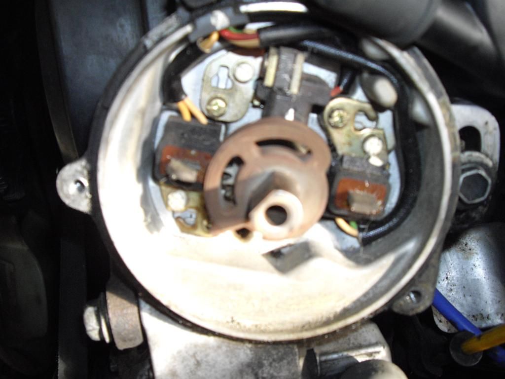
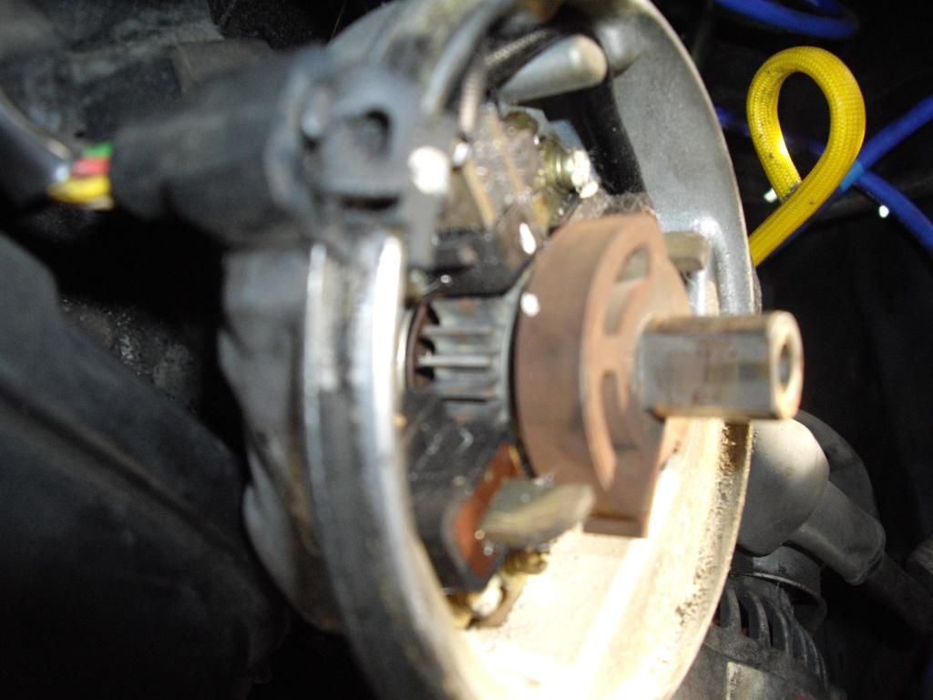
So how do I inspect this style distributor?
So how do I inspect this style distributor?
Nov 3, 2012 | 06:33 AM
#2
Registered User
Joined: Jan 2007
Posts: 6,106
Likes: 27
The older distributors(like yours) are basically the same, they just look different than the newer ones. The air gap specs for the NE and G signal rotors, and the resistance specs for those circuits are the same for all 3VZ-E distributors. But to test the circuits you need to know which wire/terminal is which. The pinout and wire colors are as follows:
EDIT:
1 = NE
2 = G1
3 = G-
4 = G2
EDIT:
1 = NE
2 = G1
3 = G-
4 = G2
Last edited by MudHippy; Nov 4, 2012 at 04:54 AM. Reason: Correct wire color confirmation
Nov 3, 2012 | 12:07 PM
#3
Thread Starter
Registered User
Joined: Nov 2011
Posts: 154
Likes: 0
Alright so I tested the terminal resistance and NE was fine. G1 reads at 440 ohms. At first G2 read open but I went and got my dad and showed him and when came back about five or so minutes later it read 440, the same as G1. My dad says that he thinks it's still fine because those two resistances are the same. Is that the case or is it a bad distributor?
Last edited by adamthedroog; Nov 3, 2012 at 12:09 PM.
Nov 3, 2012 | 03:56 PM
#4
Registered User
Joined: Jan 2007
Posts: 6,106
Likes: 27
Since I don't have the specs for the older distributor, I'm inferring they're the same. Because AFAIK, and/or have been told, they are. Supposedly you can swap either style of distributor into any 3VZ-E and it will work(if wired correctly). So why/how that would be possible if the specs are different is beyond me.
But, I'll tell you what. Let me go check mine for reference(old style like yours). I know it's good(works good). Then we'll see if my case holds any more/less water. Could be a few minutes...I'll get back to you on that ASAP.
But, I'll tell you what. Let me go check mine for reference(old style like yours). I know it's good(works good). Then we'll see if my case holds any more/less water. Could be a few minutes...I'll get back to you on that ASAP.
Last edited by MudHippy; Nov 3, 2012 at 04:00 PM.
Nov 3, 2012 | 05:36 PM
#6
Registered User
Joined: Jan 2007
Posts: 6,106
Likes: 27
Alrighty then! I finally got it all figured out. First, I was wrong about the wire colors. And my initial test results were wrong too, until I figured out what was really going on. That happened when I tried switching the assignment of the yellow wire with the white wire, and suddenly it all made sense. So let me correct my previous statement, the pinout and wire colors are as follows:
1 = NE
2 = G1
3 = G-
4 = G2
My final results were:
NE-G- = 159.6Ω
G1-G- = 172.3Ω
G2-G- = 175.5Ω
All good!
Go test yours again, and see what you come up with. BTW, I was getting ~320Ω from the G1/G2 circuits when I had NE and G- switched up.
One more thing, all 4 of the wire colors get recoded at the wiring harness end of the connector. Which is what all the reference material states as the pinout wire colors for the distributor. Which in fact are really the pinout/wire colors for the wiring harness's distributor connector (and the wire colors for the corresponding ECU pins/terminals). And they are as follows:
1 = green(NE)
2 = white(G1)
3 = black(G-)
4 = red(G2)
Hence the confusion...
Last edited by MudHippy; Feb 16, 2013 at 08:52 AM.
Trending Topics
Jan 29, 2013 | 06:50 PM
#8
Thread Starter
Registered User
Joined: Nov 2011
Posts: 154
Likes: 0
Ripped the old posts from another distributor at a junkyard that were miraculously within spec. I just have one last question. Do all three posts (crankshaft and camshaft sensors) have the same air gap? I think 0.2mm - 0.4mm?
Feb 20, 2020 | 10:54 AM
#9

Registered User
Joined: Feb 2020
Posts: 7
Likes: 0
1988 3VZE Distributor pinout??
im confused...easily done- first Yota. I�m trying to test a distributor but I can�t find the correct pin diagram for the 1988 with the correct colors, nor can I find the correct sequence to test the ohms� You seem to be the guru on here any help would be appreciated.
I�ll ask you in advance to please be very specific- it�s a foreign language
much appreciated
I have 4 wires- RED,GREEN,WHITE and YELLOW
I�ll ask you in advance to please be very specific- it�s a foreign language
much appreciated
I have 4 wires- RED,GREEN,WHITE and YELLOW
Alrighty then! I finally got it all figured out. First, I was wrong about the wire colors. And my initial test results were wrong too, until I figured out what was really going on. That happened when I tried switching the assignment of the yellow wire with the white wire, and suddenly it all made sense. So let me correct my previous statement, the pinout and wire colors are as follows:
1 = NE
2 = G1
3 = G-
4 = G2
My final results were:
NE-G- = 159.6Ω
G1-G- = 172.3Ω
G2-G- = 175.5Ω
All good!
Go test yours again, and see what you come up with. BTW, I was getting ~320Ω from the G1/G2 circuits when I had NE and G- switched up.
One more thing, all 4 of the wire colors get recoded at the wiring harness end of the connector. Which is what all the reference material states as the pinout wire colors for the distributor. Which in fact are really the pinout/wire colors for the wiring harness's distributor connector (and the wire colors for the corresponding ECU pins/terminals). And they are as follows:
1 = green(NE)
2 = white(G1)
3 = black(G-)
4 = red(G2)
Hence the confusion...
1 = NE
2 = G1
3 = G-
4 = G2
My final results were:
NE-G- = 159.6Ω
G1-G- = 172.3Ω
G2-G- = 175.5Ω
All good!
Go test yours again, and see what you come up with. BTW, I was getting ~320Ω from the G1/G2 circuits when I had NE and G- switched up.
One more thing, all 4 of the wire colors get recoded at the wiring harness end of the connector. Which is what all the reference material states as the pinout wire colors for the distributor. Which in fact are really the pinout/wire colors for the wiring harness's distributor connector (and the wire colors for the corresponding ECU pins/terminals). And they are as follows:
1 = green(NE)
2 = white(G1)
3 = black(G-)
4 = red(G2)
Hence the confusion...

Thread
Thread Starter
Forum
Replies
Last Post
nframe
3.4 Swaps
3
Aug 16, 2015 09:03 AM
88yodabasket
86-95 Trucks & 4Runners
15
Jul 13, 2015 01:32 PM


