
‘82 4x4, GM LV3 4.3l Engine Swap
 Feb 5, 2019 | 03:08 PM
#41

Registered User
Joined: Feb 2019
Posts: 1
Likes: 0
Check out 150tunes.com for your wiring harness. They clean up existing harnesses for $250. I think they are doing the genV stuff. I think the guys name is Dwayne Hartwig. Don't quote me on that. I've heard really good things about their work though. I'm planning on doing this same swap in to a 1963 cj6. I may be picking your brain in a few months. Hope this helps.
Feb 11, 2019 | 08:11 PM
#42
Thread Starter
Registered User
Joined: Dec 2017
Posts: 96
Likes: 24
From: Flower Mound, Texas
jazz1, a carb sounds good right about now! Unfortunately, its no cost efficient enough yet for a company to make any kind of intake for this thing. With the direct injection I'm guessing it might not even be feasible.
Hey Nick Graef, thanks for the tip. I'm definitely going to check them out. I've reached the point of insanity with the engine harness.
Progress has been slow and got even slower due to some family stuff going on. I have just been working on the chassis wiring and converting the Toyota column wiring to the Painless harness. (not some Painless) I think I have everything figured out. I made a test circuit with a switch and inline fuse to test everything. I'll post what goes where if its successful.
Feb 17, 2019 | 07:35 PM
#43
Thread Starter
Registered User
Joined: Dec 2017
Posts: 96
Likes: 24
From: Flower Mound, Texas
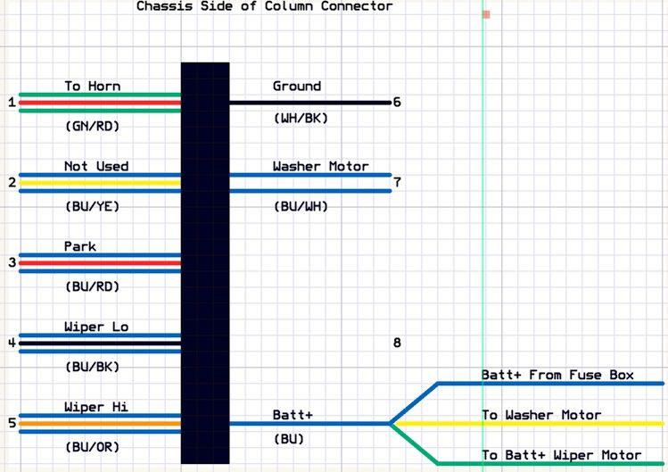
Here is the Wiper Motor Wiring Diagram that worked for me. There is no relay in this setup. I'm still working on the turn signal switch and will post after I test it.
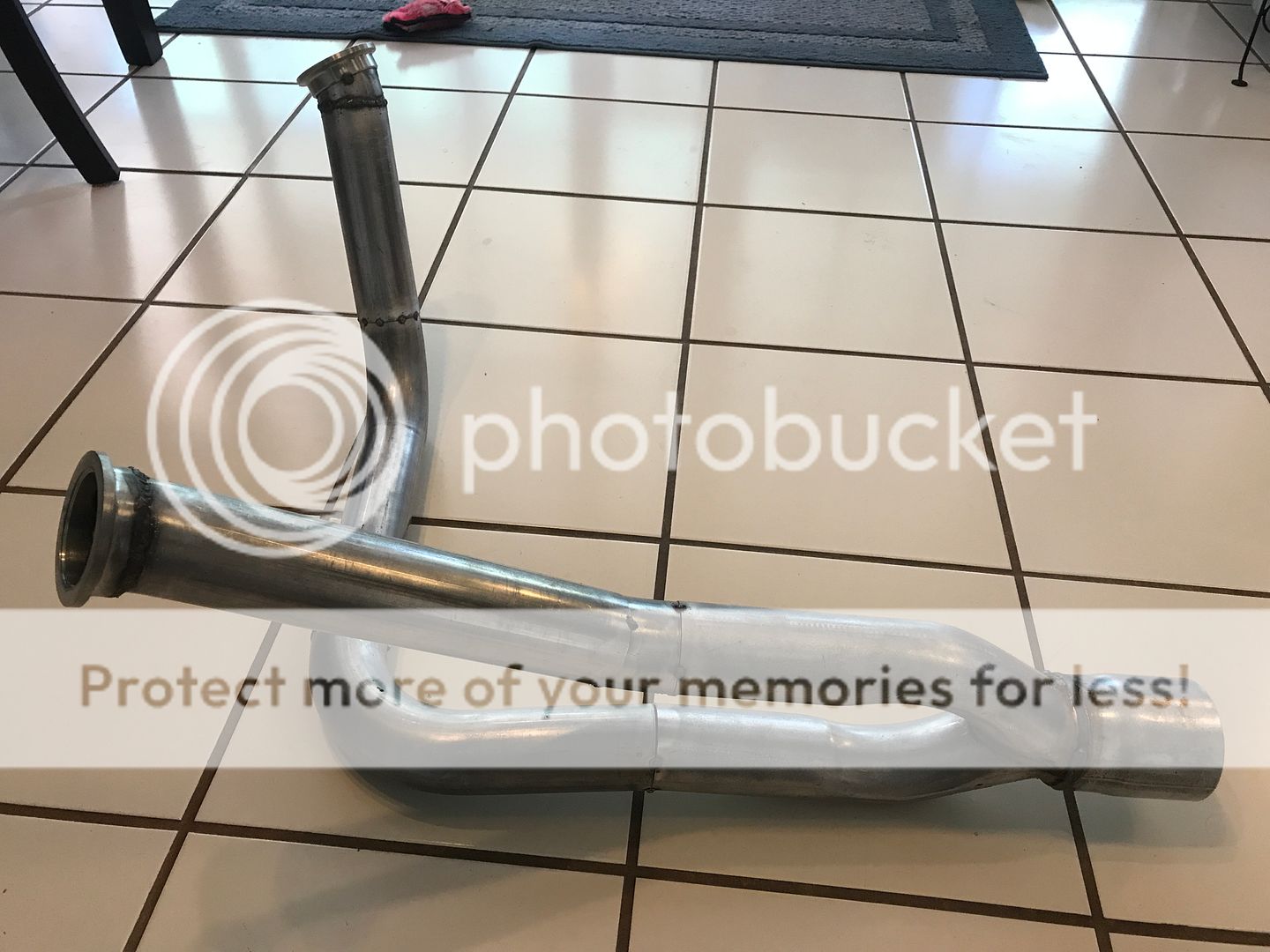
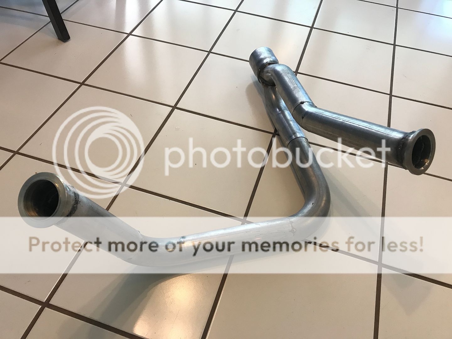
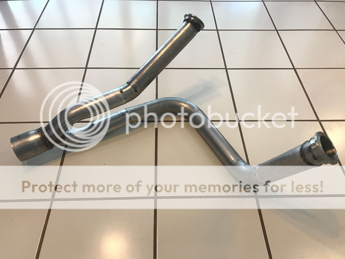
I started working on the exhaust manifold. I've been posting relative information on the LS1Tech forum about motor stuff but some might find this part interesting. The exhaust manifold on these motors are cast steel instead of cast iron. Weldable. The LS1 guys modify them for turbo setups. So, why couldn't I do it for a normal application? Cut the flange off and grind flat to the angle you need. I used schedule 40 steel pipe. Those are two 45 degree sections to make the necessary bends to clear the frame.
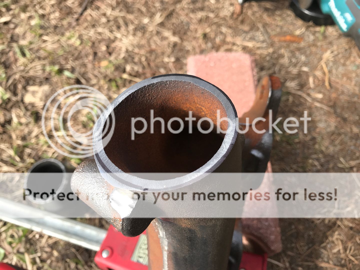
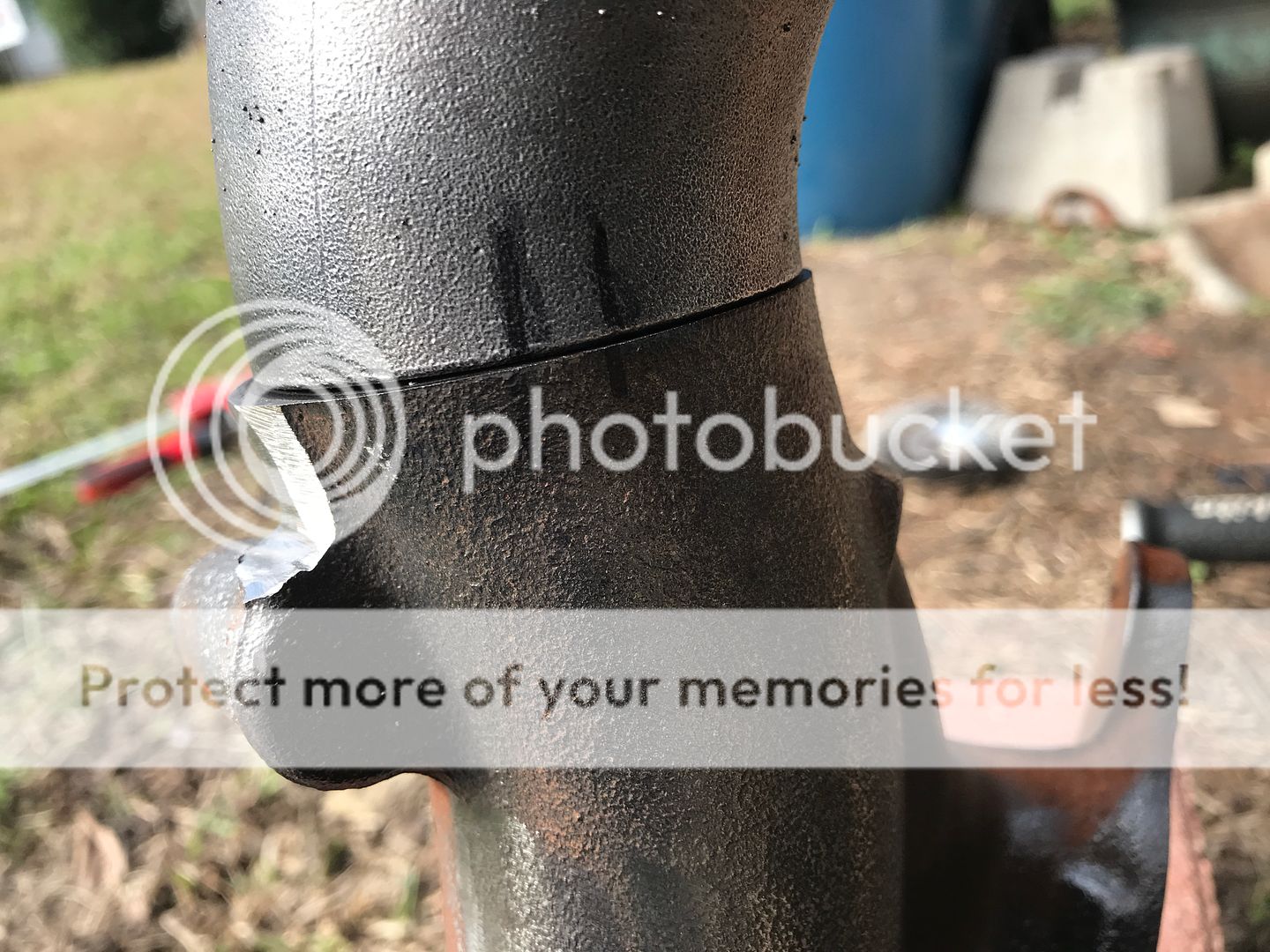
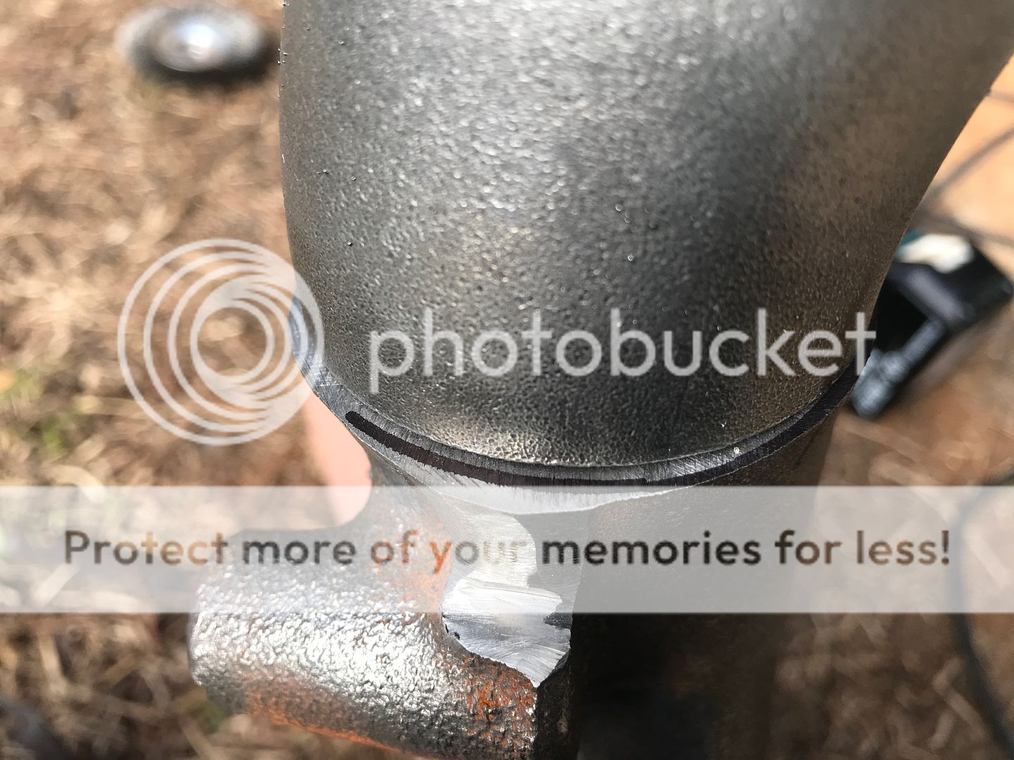
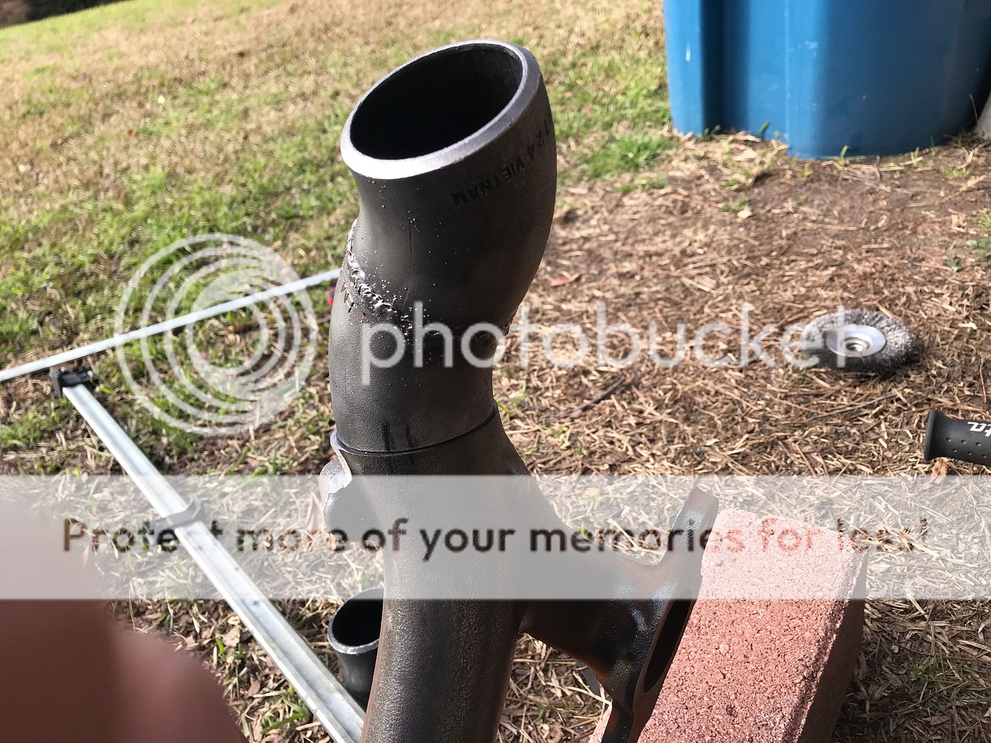
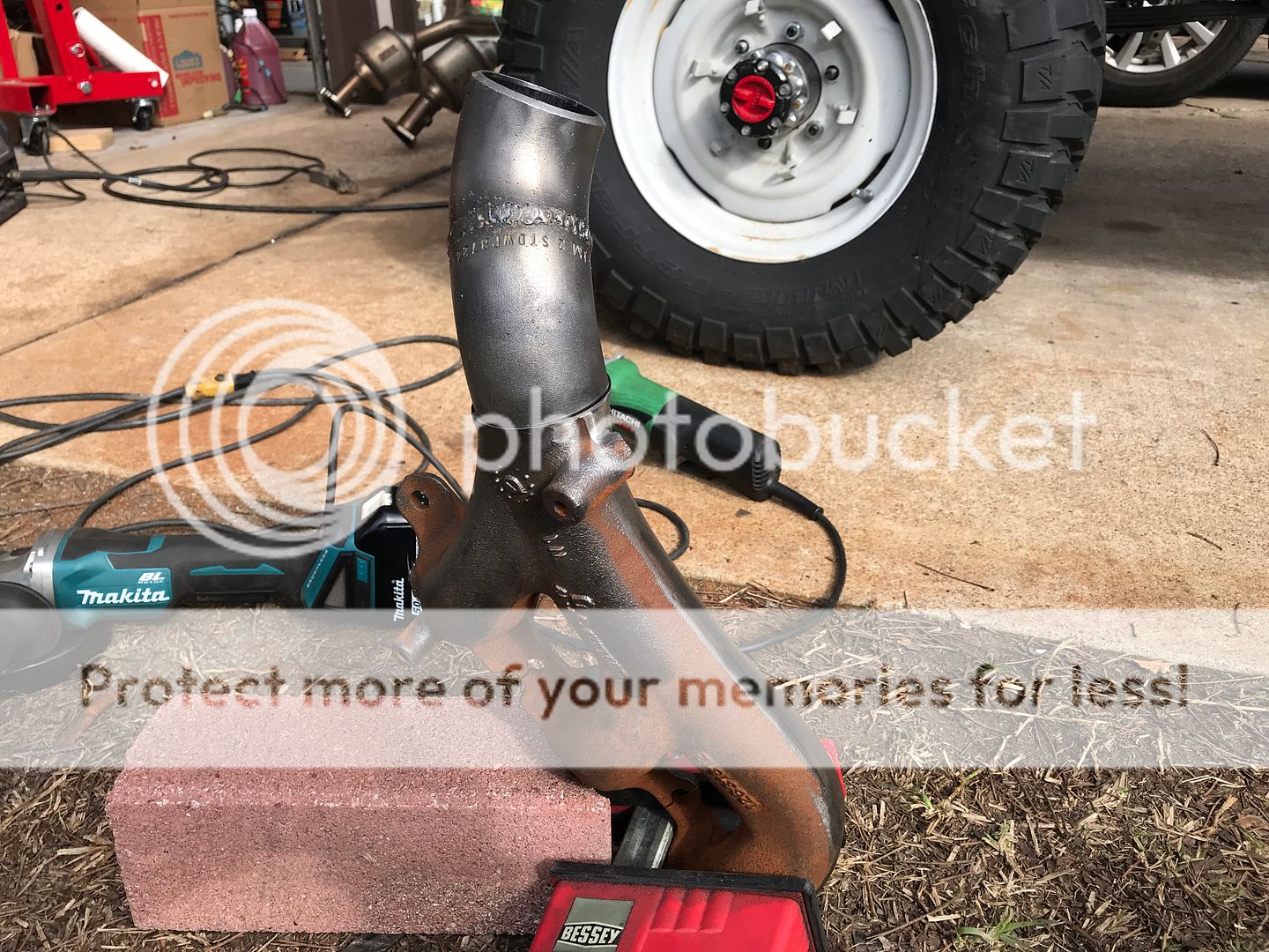
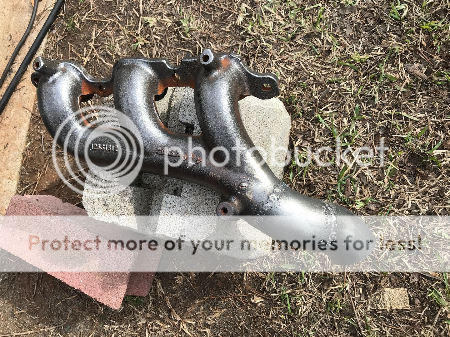
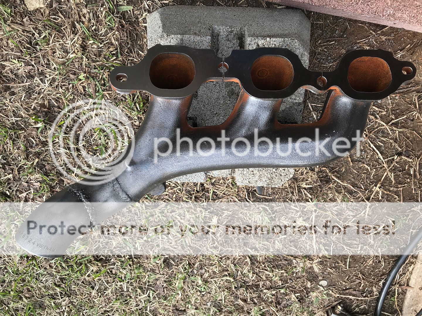
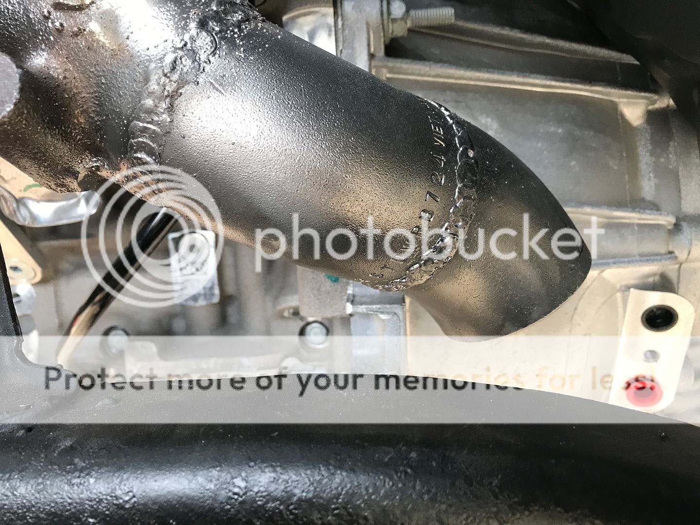
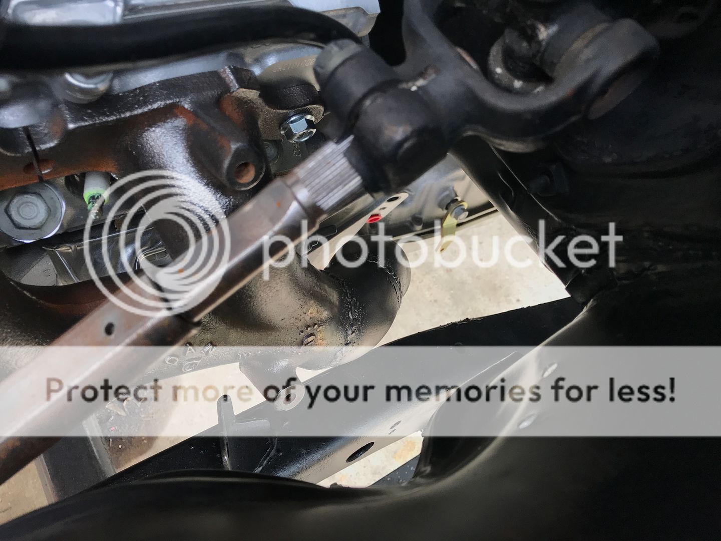
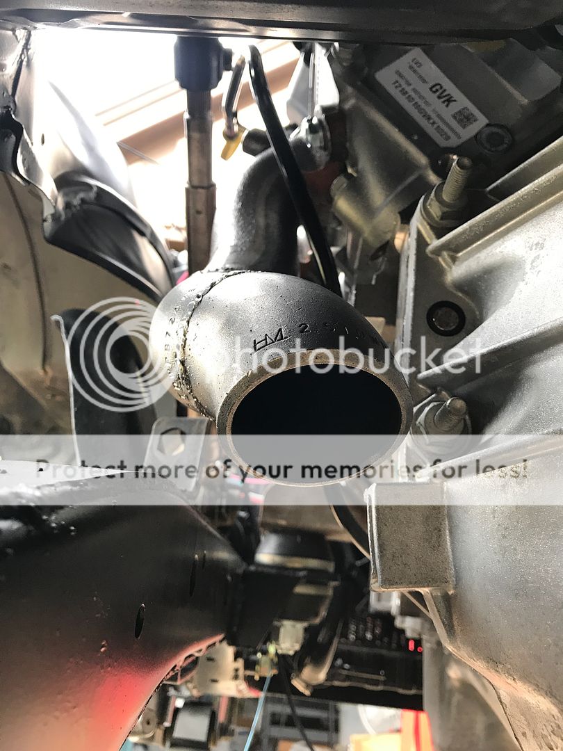
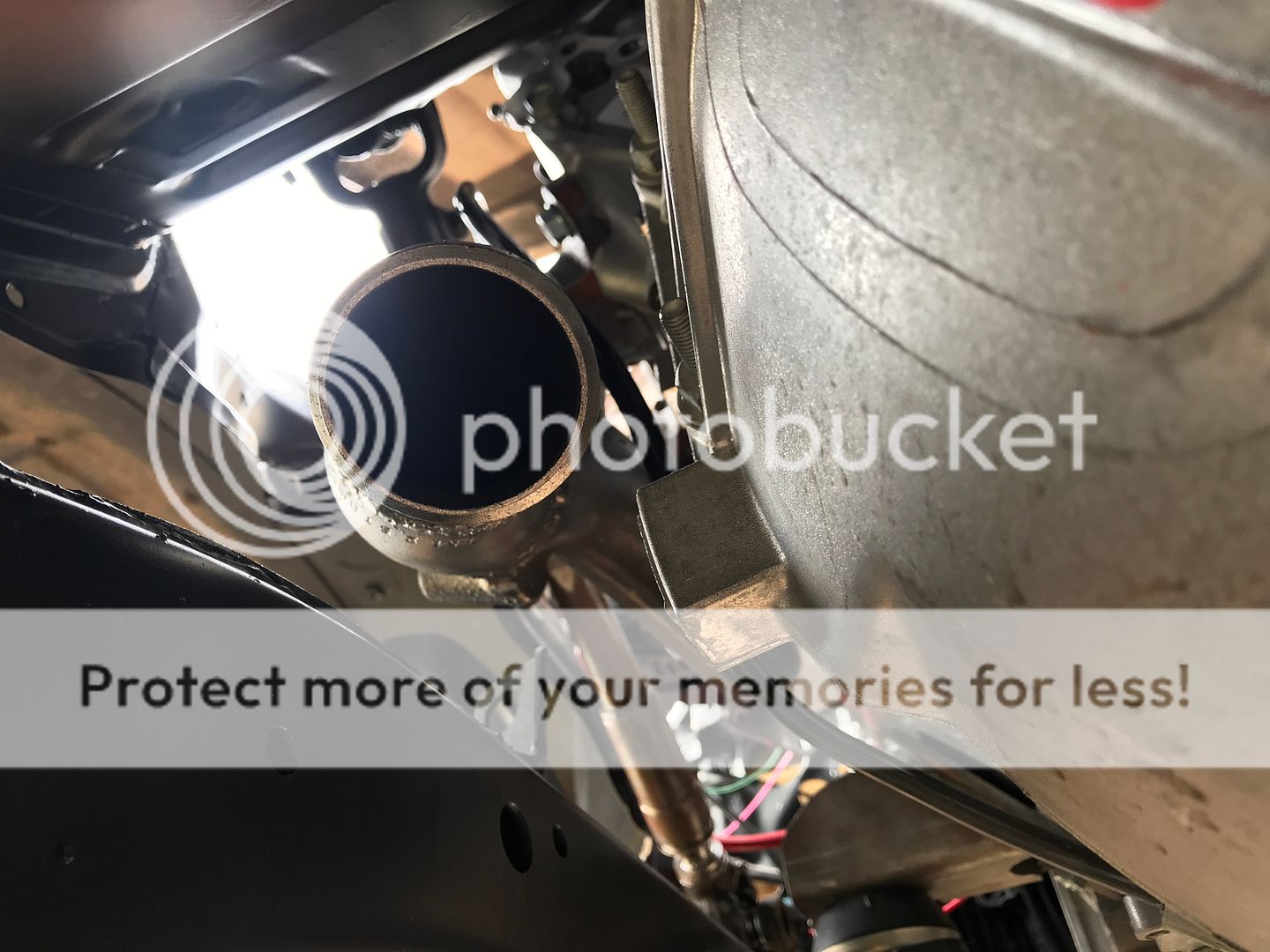

I started working on the exhaust manifold. I've been posting relative information on the LS1Tech forum about motor stuff but some might find this part interesting. The exhaust manifold on these motors are cast steel instead of cast iron. Weldable. The LS1 guys modify them for turbo setups. So, why couldn't I do it for a normal application? Cut the flange off and grind flat to the angle you need. I used schedule 40 steel pipe. Those are two 45 degree sections to make the necessary bends to clear the frame.


 Jul 7, 2019 | 02:21 PM
#46
Thread Starter
Registered User
Joined: Dec 2017
Posts: 96
Likes: 24
From: Flower Mound, Texas
Howdy to everyone following this craziness. It's been a while since my last update. I'll try to post everything I did in order of completion. I'll start with the Vintage Air A/C. It's the Gen 2 Compaq unit. I bought everything for it at SACHSE ROD SHOP
3904 MILES RD , SACHSE, TX, 75048. I called them first and had a great talk about Vintage Air and he answered all of my newb questions. I drove over and he worked with me in putting a kit together for my truck. I have not seen service from any establishment like this since I was very young. They are just super to work with and extremely knowledgeable about everything. In fact, I originally bought the Mini version and when I got home and took it out of the box, one of the wires was severed. It looked like it happened during the boxing of the unit. I called right away and he said bring it back and I'll give you a different one. It wasn't their fault at all. It is shipped to them in the box from the factory. Anyway, he took the time to show me how to cut all of the hoses and mark them so I could bring them back for them to crimp. Viola, custom length hoses! There are still a few hoses I have to mark and get crimped, but that's just because I'm not sure how the plumbing to the condenser is going to go.
Vintage Air Gen2 Compaq
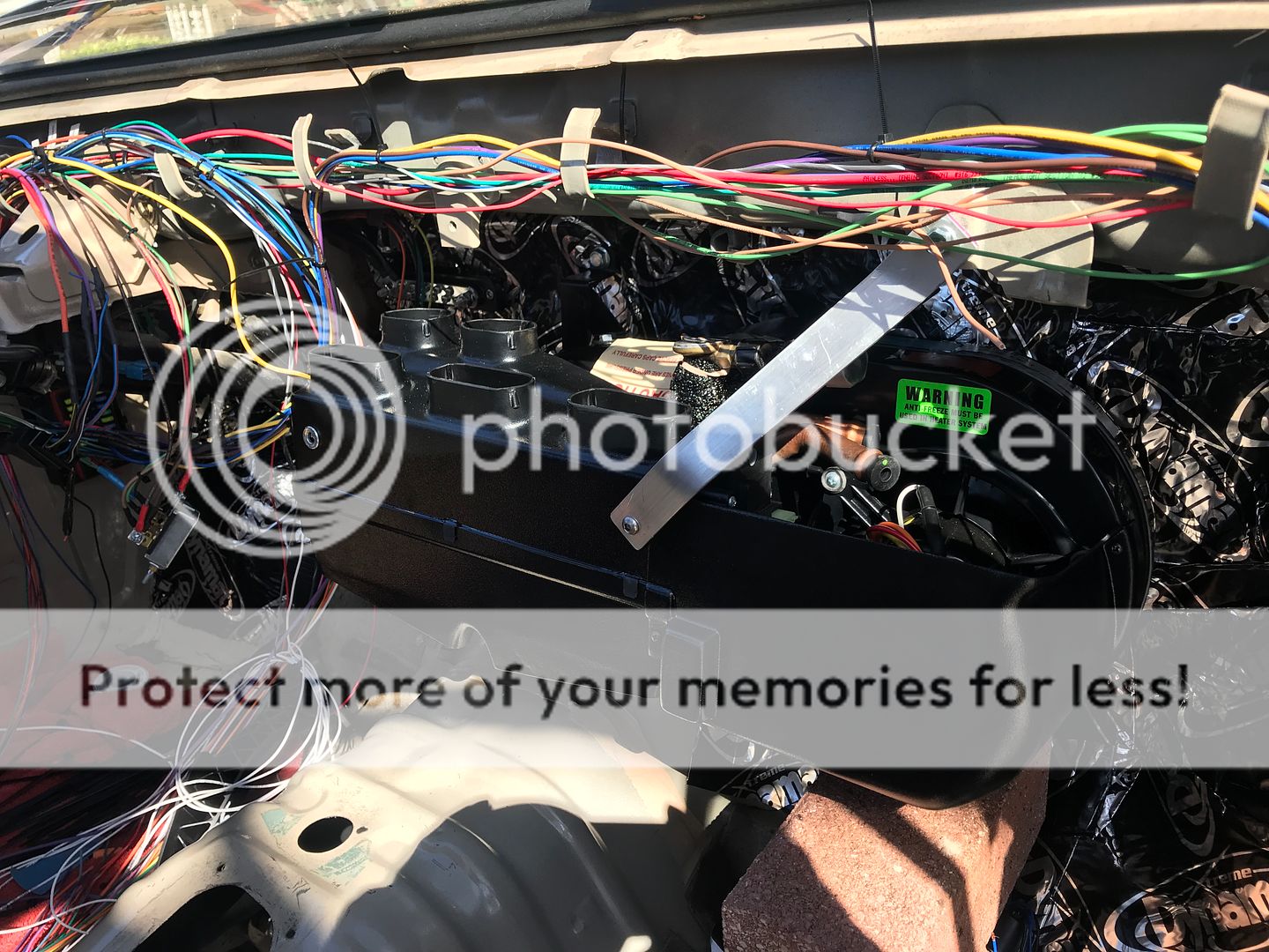
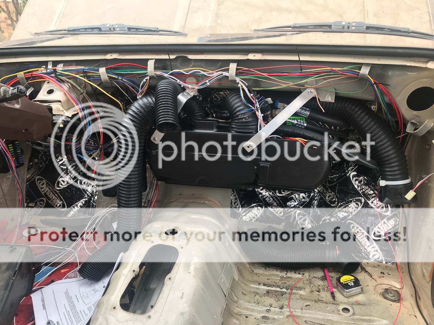
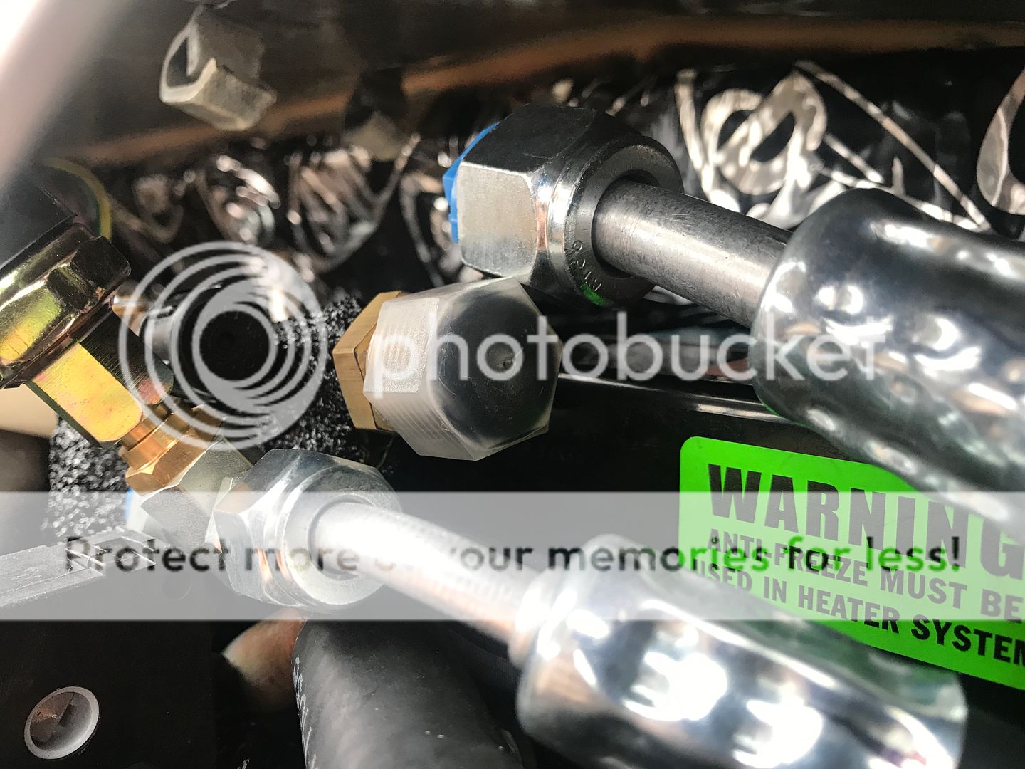
Heater and A/C lines going through the firewall to the engine bay
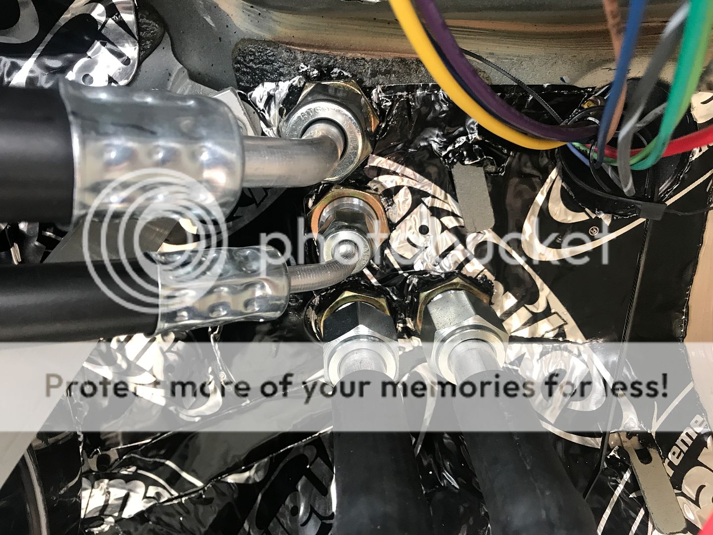
From the engine bay side
Make sure not to connect the lines to the unit until you are ready to have it charged.
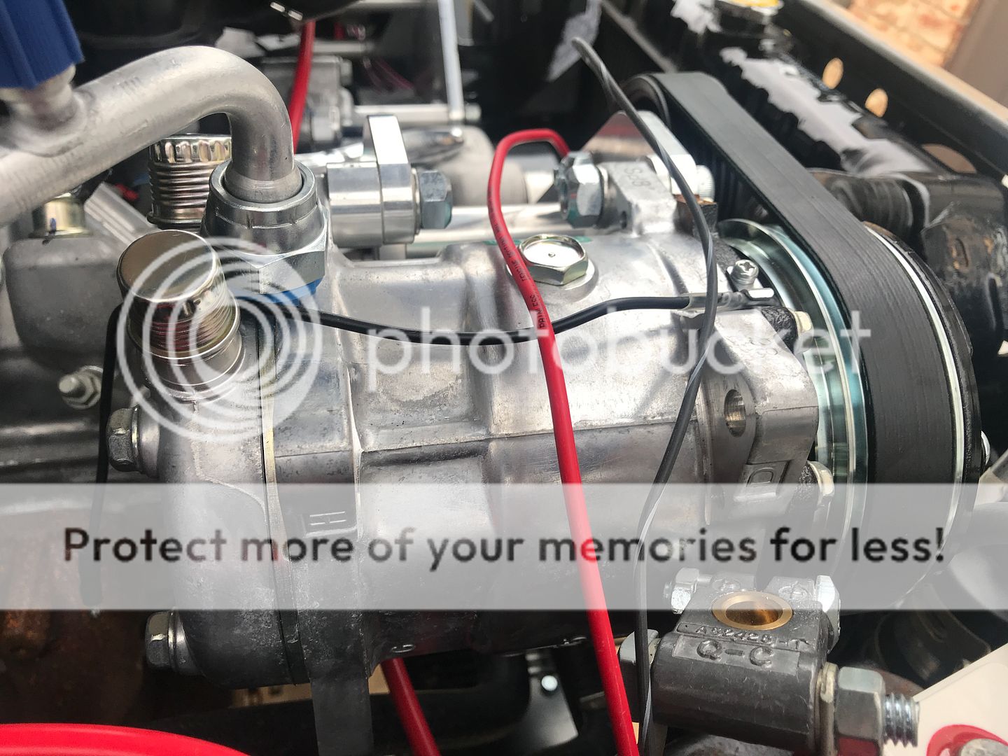
Same with the compressor
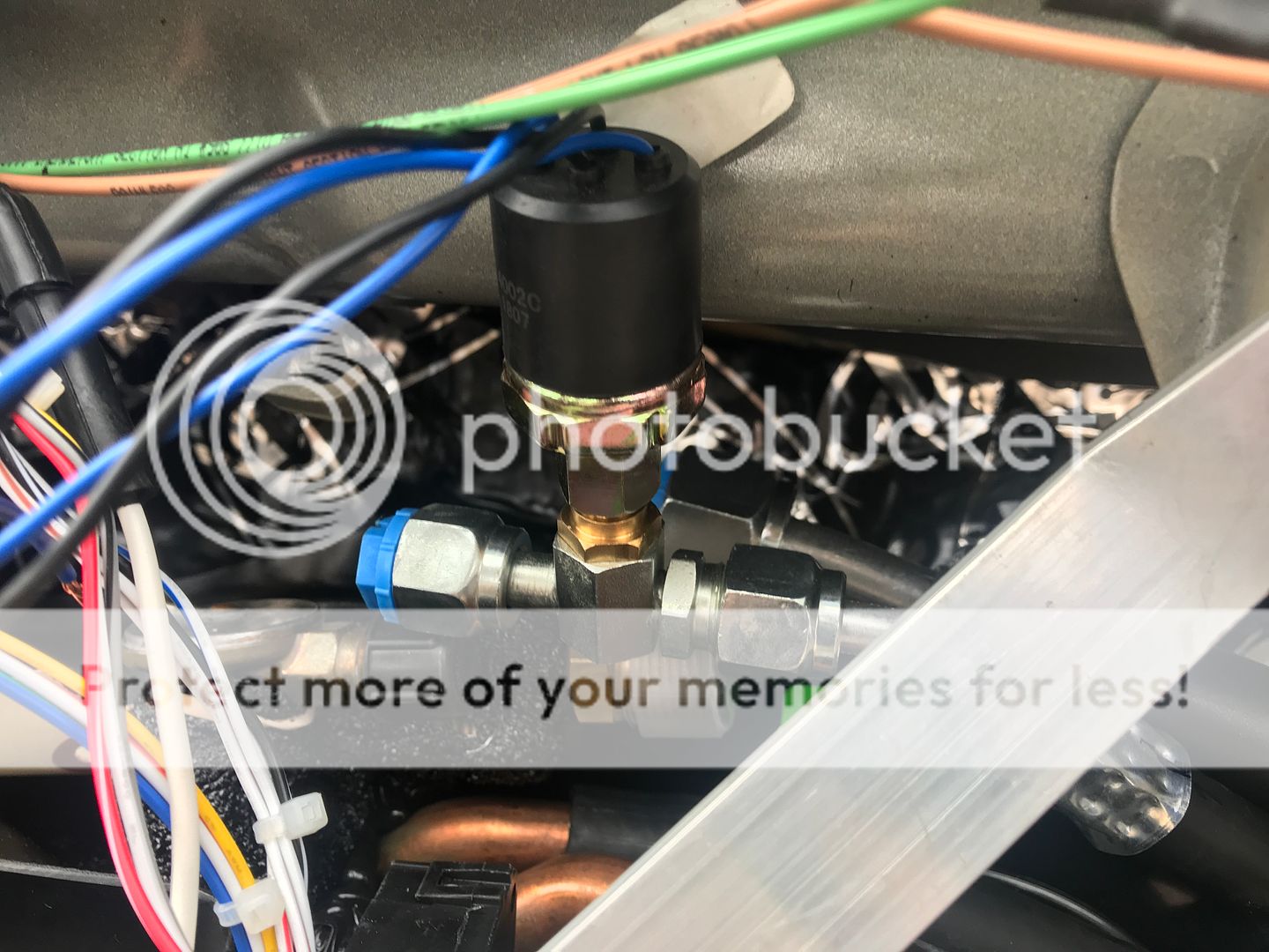
This is the trinary switch. I protects your compressor from getting damaged if there is too low or too high of pressure. The third part of the "tri" is a circuit that engages the PWM fan controller when the A/C is powered on.
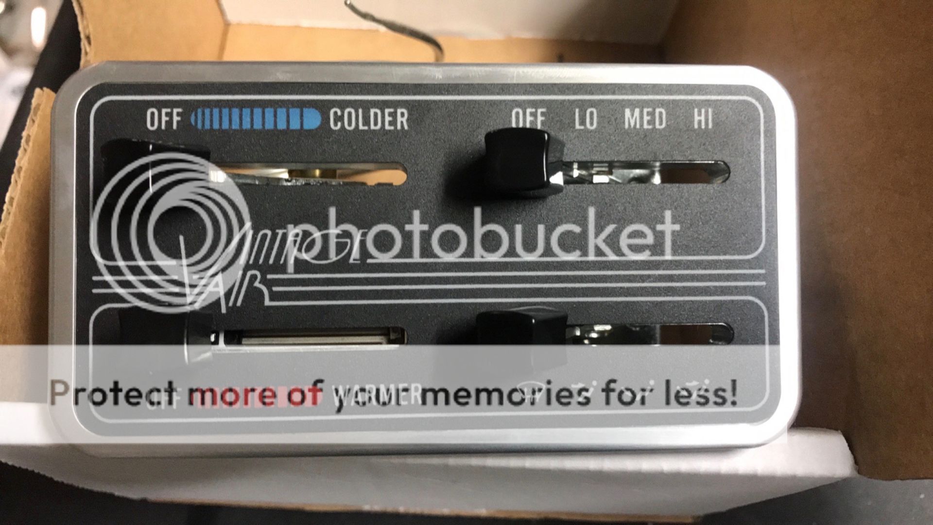
I chose this controller. It looks pretty vintage for an early 80's vehicle
3904 MILES RD , SACHSE, TX, 75048. I called them first and had a great talk about Vintage Air and he answered all of my newb questions. I drove over and he worked with me in putting a kit together for my truck. I have not seen service from any establishment like this since I was very young. They are just super to work with and extremely knowledgeable about everything. In fact, I originally bought the Mini version and when I got home and took it out of the box, one of the wires was severed. It looked like it happened during the boxing of the unit. I called right away and he said bring it back and I'll give you a different one. It wasn't their fault at all. It is shipped to them in the box from the factory. Anyway, he took the time to show me how to cut all of the hoses and mark them so I could bring them back for them to crimp. Viola, custom length hoses! There are still a few hoses I have to mark and get crimped, but that's just because I'm not sure how the plumbing to the condenser is going to go.
Vintage Air Gen2 Compaq


Heater and A/C lines going through the firewall to the engine bay

From the engine bay side

Make sure not to connect the lines to the unit until you are ready to have it charged.

Same with the compressor

This is the trinary switch. I protects your compressor from getting damaged if there is too low or too high of pressure. The third part of the "tri" is a circuit that engages the PWM fan controller when the A/C is powered on.


I chose this controller. It looks pretty vintage for an early 80's vehicle

Last edited by Trueblue93; Jul 7, 2019 at 02:27 PM. Reason: delete a picture
Jul 7, 2019 | 02:43 PM
#47
Thread Starter
Registered User
Joined: Dec 2017
Posts: 96
Likes: 24
From: Flower Mound, Texas
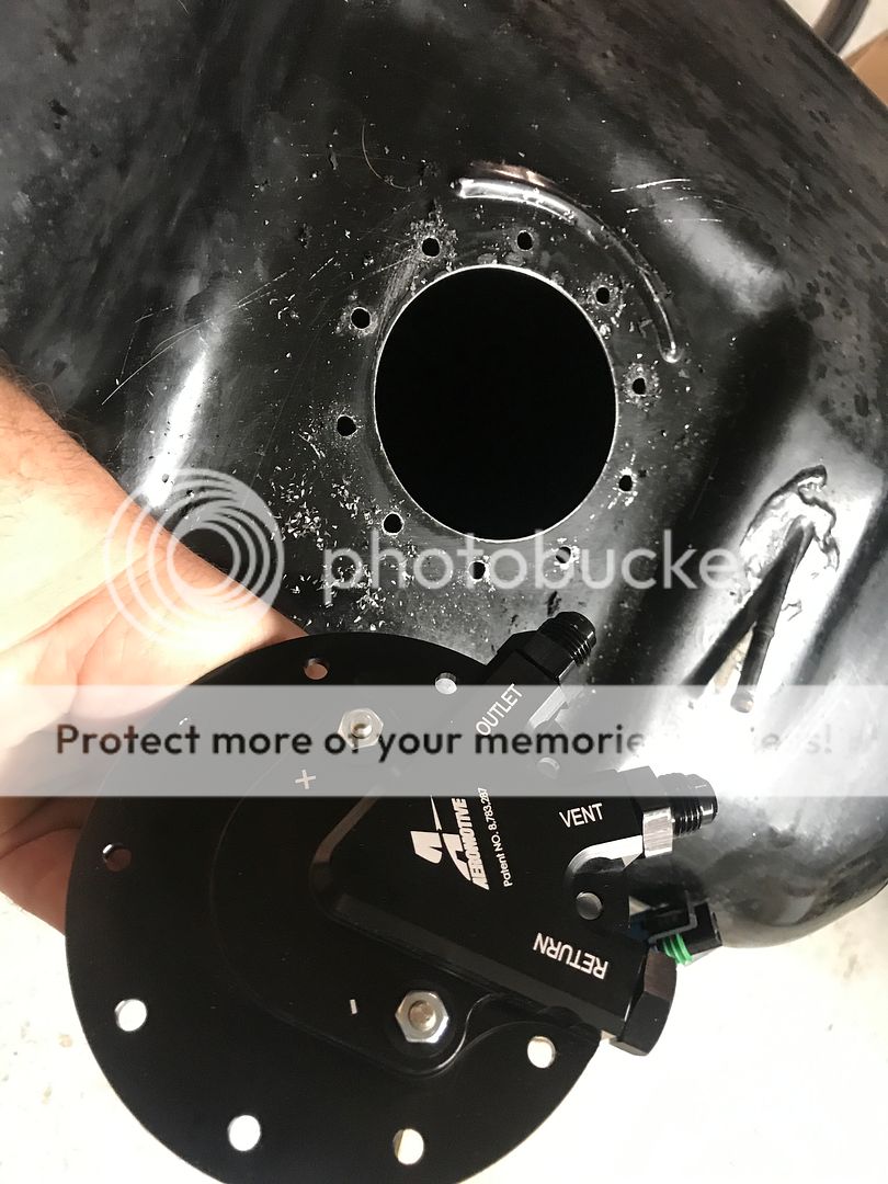
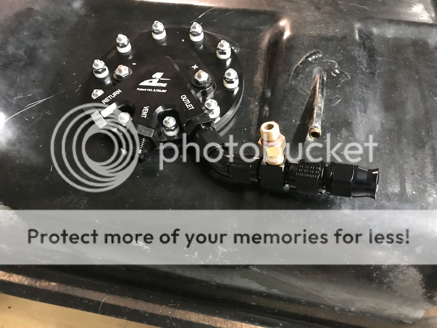
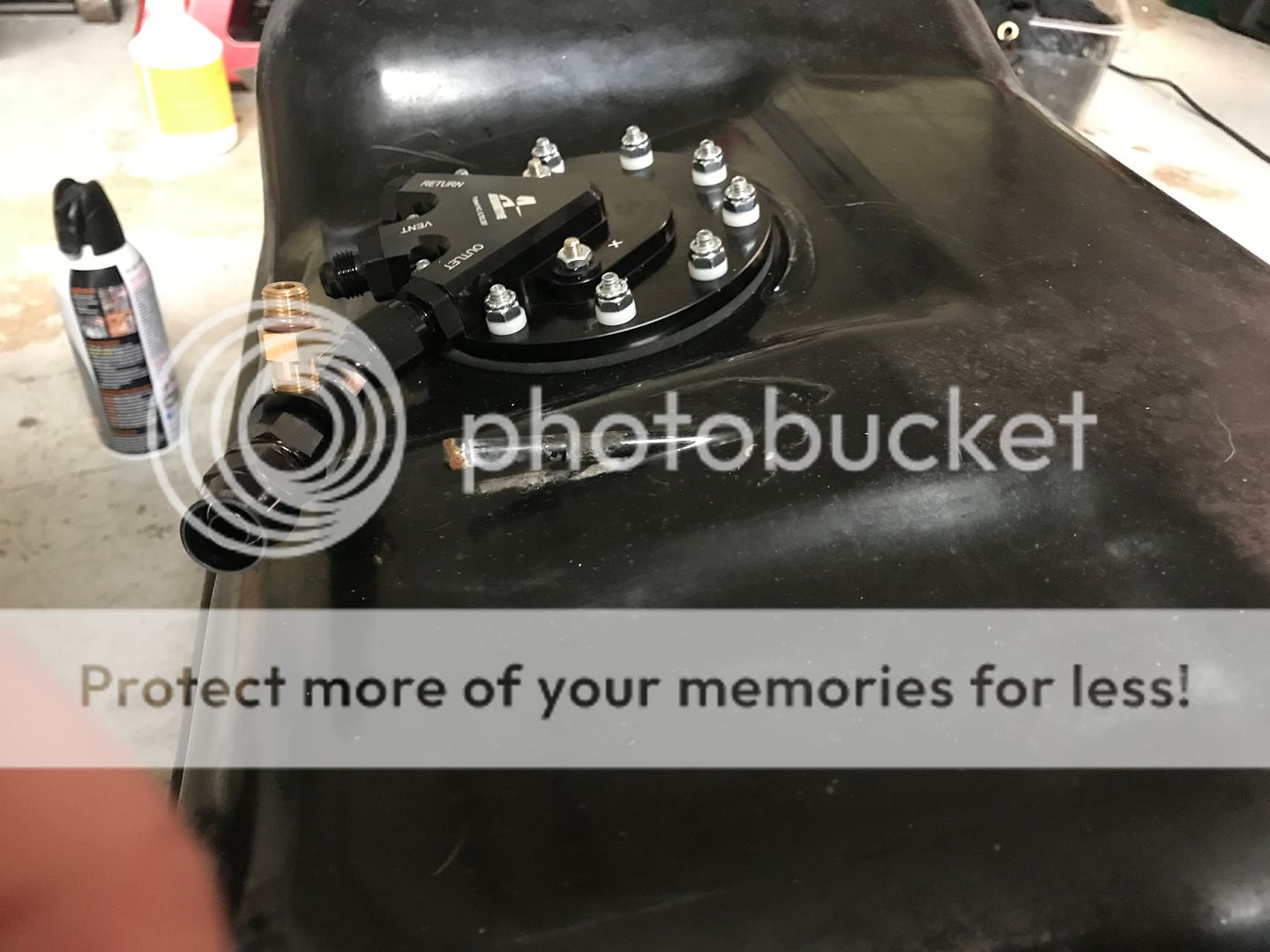
I worked on the gas tank next. I didn't get many pics of the process. I pulled it, emptied it, cleaned it, and drilled it for my new in tank fuel pump. It's one of the few aftermarket pumps that can handle a pwm controller. I stayed with the GM original equipment fuel delivery system. Since it's a direct injection motor, it needs a lot of pressure to run properly. It's a very complicated system. The in tank pump provides anywhere from 45 to upwards of 65 psi of pressure to a second, camshaft driven pump that increases psi to between 2000 and 2900 psi. Crazy! Anyway, it uses an inline fuel sensor that the computer reads and then sends a signal to the fuel pump modulator which in turn sends a pwm signal to the in tank pump. This keeps the line psi where it needs to be according to engine demand. There is no return line in this system. The pump is the Aeromotive Stealth 340 or something like that. It's a pretty neat kit that you can add to just about any fuel tank. You'll need an after market fuel sensor adaptor to install this. I got mine from Vaporworx. The sensor plug doesn't match the harness plug, but more on that later. I'm going to have to call Mitch at SwapTime.
I can take more pictures and post if requested. Those are the only ones I have taken as of now.


I can take more pictures and post if requested. Those are the only ones I have taken as of now.
Jul 12, 2019 | 01:39 PM
#49
Thread Starter
Registered User
Joined: Dec 2017
Posts: 96
Likes: 24
From: Flower Mound, Texas
The next thing I worked on was the brake system.
It seems I may have lost some of the photos but I'll try to explain what I did. A lot of this information can be looked up on Youtube. Things like making brake lines.
I decided to go with the GM 7" dual diaphragm. I'm pretty sure this is the one I bought, I can't quite remember.
https://www.summitracing.com/parts/tff-2121nb-1
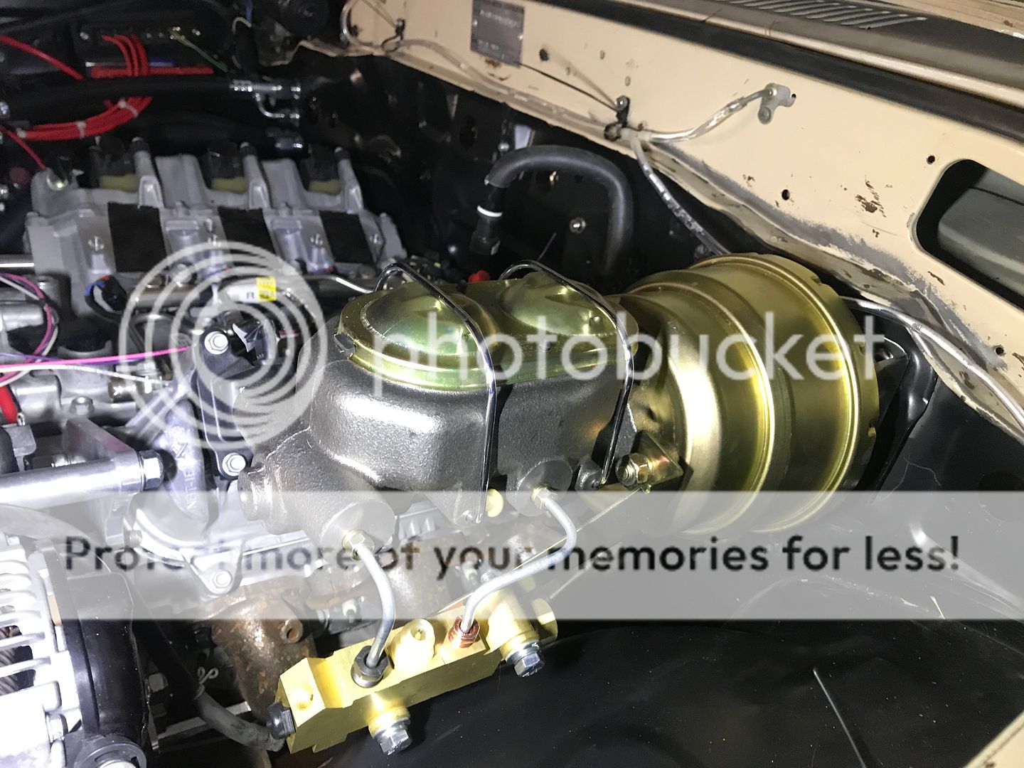
I made a adaptor bracket buy cutting a piece of 1.5"x 3" rectangular tubing in half long ways. I rounded the ends over to kind of match the booster. This was necessary because the bolt patterns for the GM booster and Toyota booster are different.
Here is the back side of the booster under the dash. You can see the steering column in the lower right hand corner.
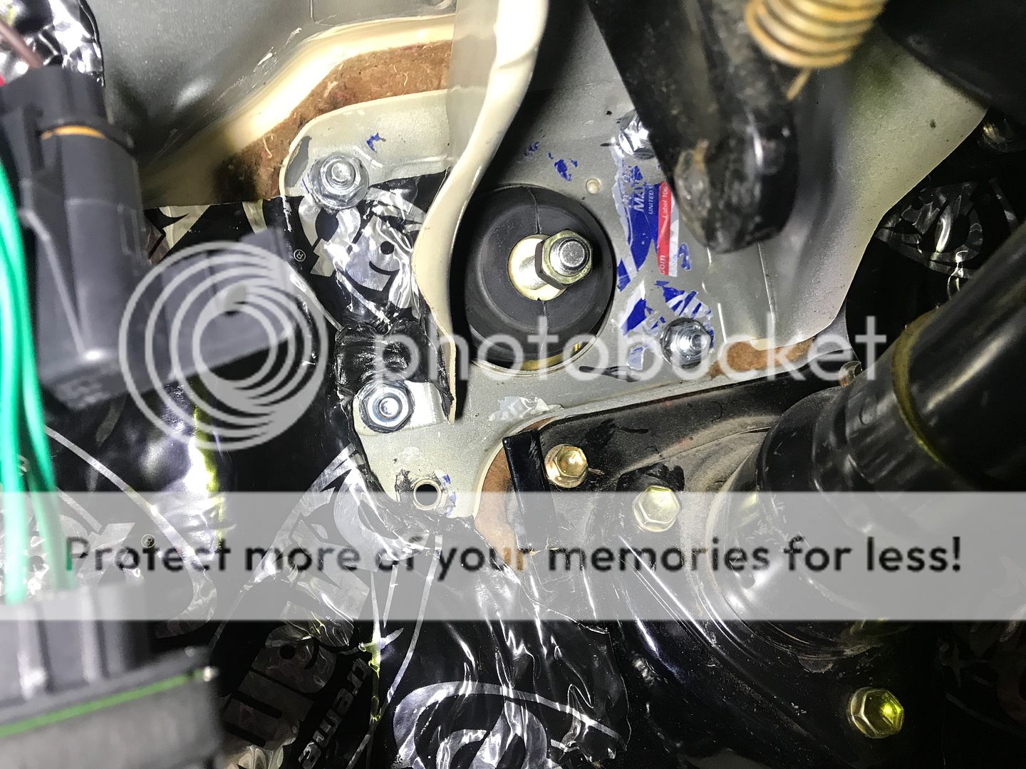
In the picture above you can see a return spring attached to the brake pedal lever. I had to buy a brake pedal to booster adaptor for this. It is a clevis type attachment on the brake pedal and screws onto the brake booster.
It looks something like this. This kit will service a few different type of brands:
https://www.summitracing.com/parts/sum-760125?rrec=true
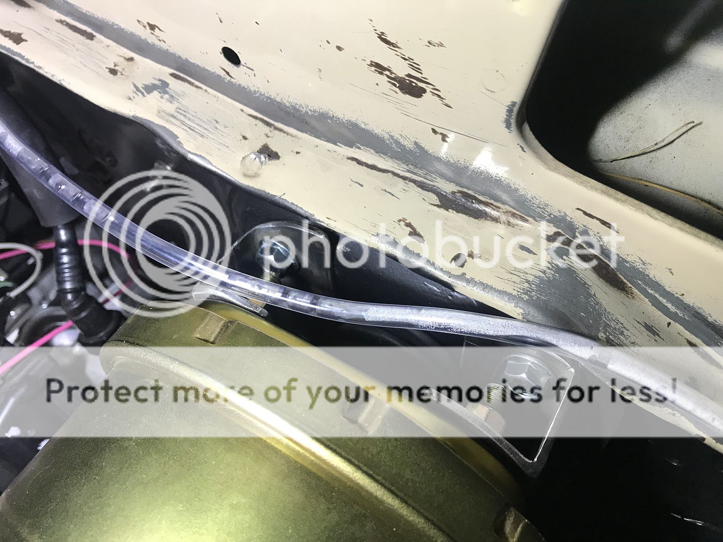
A few more random pics
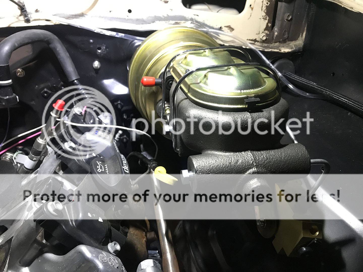
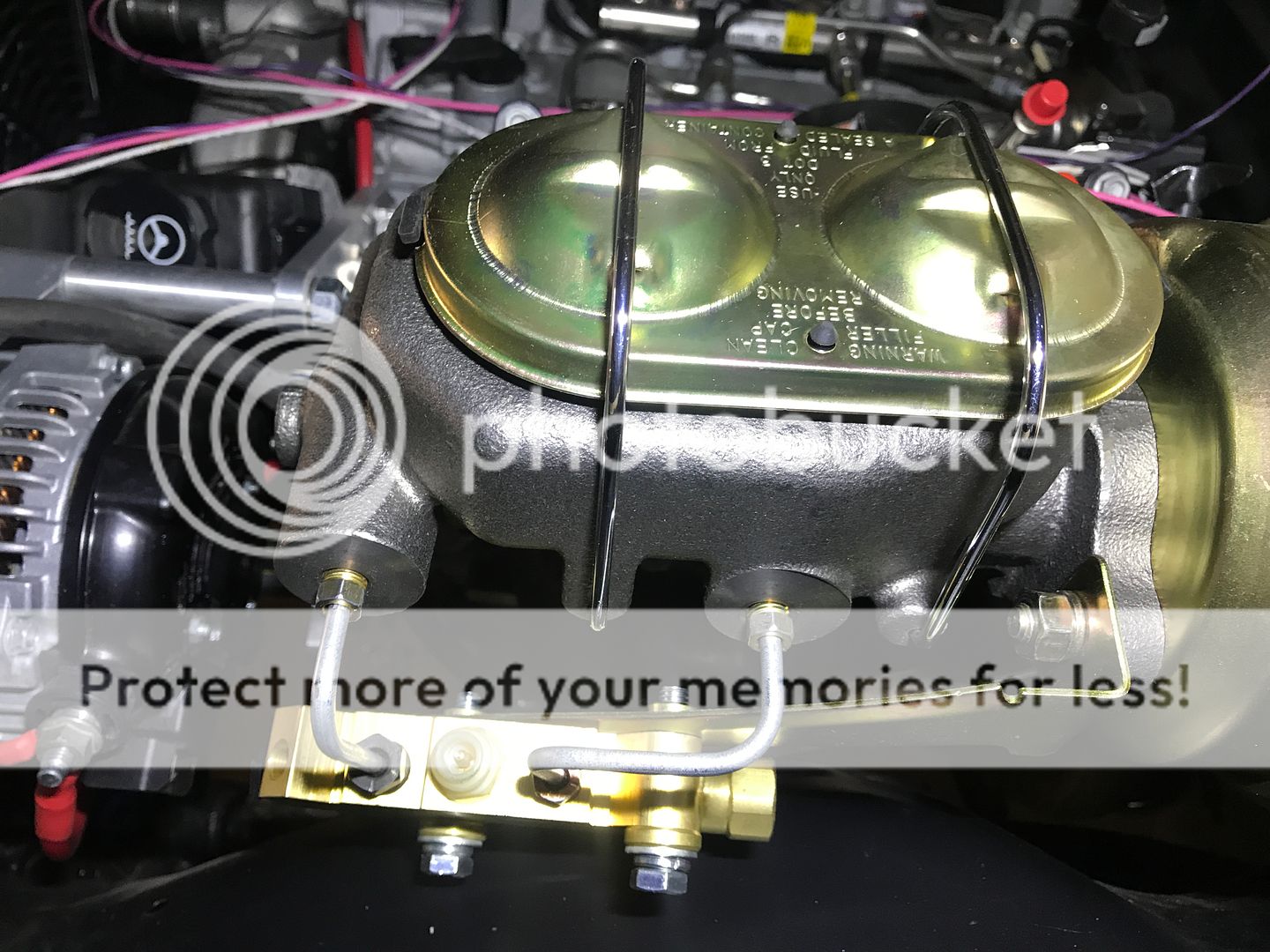
I've been told by a few individuals that these GM master cylinders are notorious for leaking. I hope that's not the case. I took a 3/8" piece of flat ground steel and some awesome sandpaper, made specifically for metal, that I had left over from my knife making days, and used that to "flat sand" the mating surface where the lid attaches. On these remanufactured master cylinder units, quality is not much of a priority for making money it seems. It didn't take long until I had a nice even, flat surface. Hopefully, this will solve any potential leak issues.
Next up were brake lines. You can look up videos on Youtube on how to make your own brake lines. I bought the Fragola 6000 series PTFE -3an hose with their brand of fittings made for this hose. This is my only experience making brake hoses but from all of the information I read about them, definitely stick to hose and fittings from the same company. Even then, make sure those fittings are made for whatever particular hose you choose. Having said all of that, here are some not very good pics.
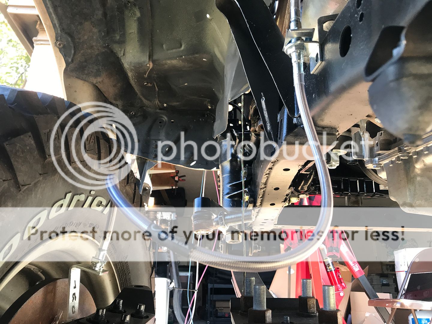
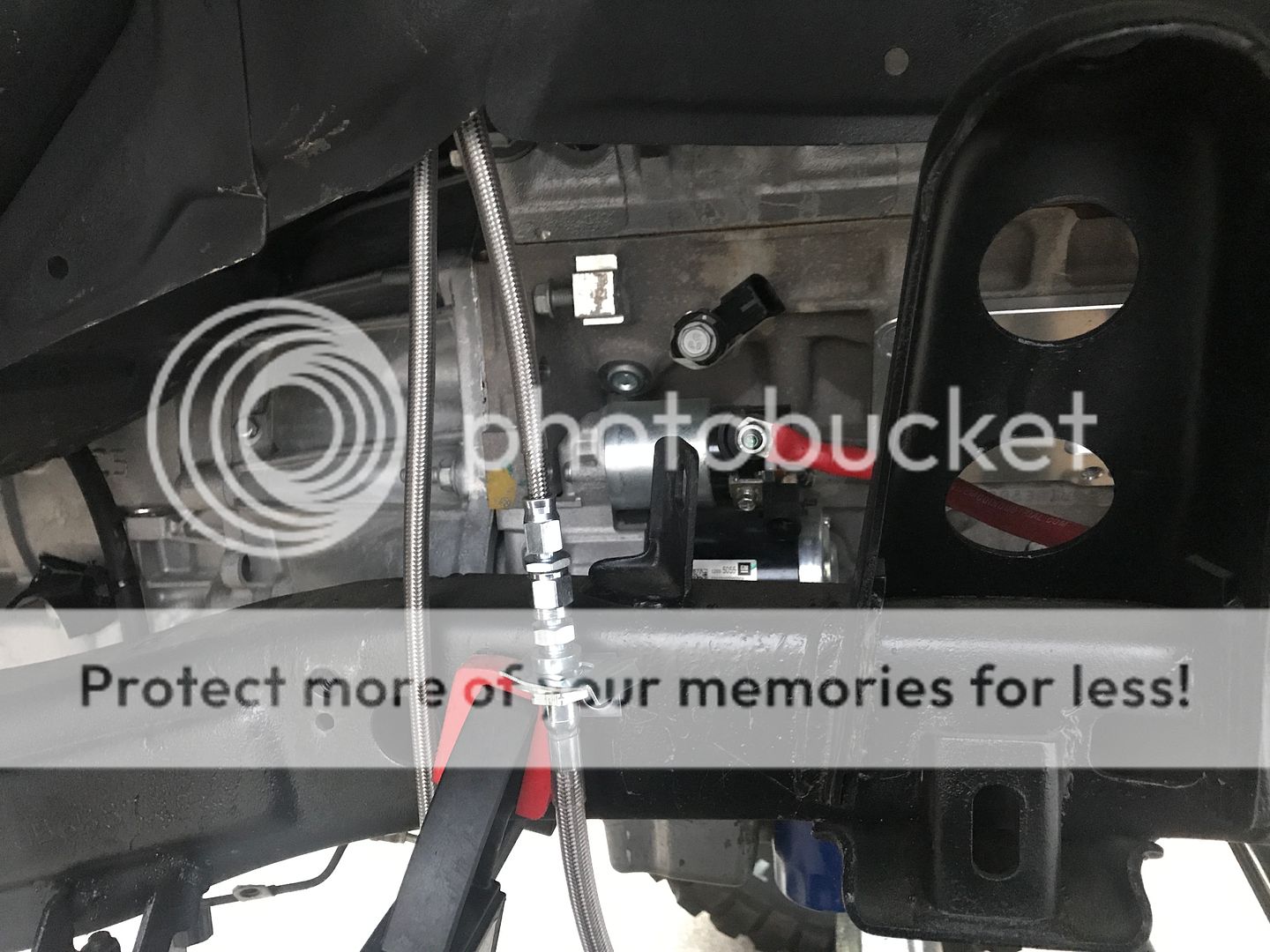
Well that was anti climatic. I l'll try to get some better pics. I thought I had more.
It seems I may have lost some of the photos but I'll try to explain what I did. A lot of this information can be looked up on Youtube. Things like making brake lines.
I decided to go with the GM 7" dual diaphragm. I'm pretty sure this is the one I bought, I can't quite remember.
https://www.summitracing.com/parts/tff-2121nb-1

I made a adaptor bracket buy cutting a piece of 1.5"x 3" rectangular tubing in half long ways. I rounded the ends over to kind of match the booster. This was necessary because the bolt patterns for the GM booster and Toyota booster are different.

Here is the back side of the booster under the dash. You can see the steering column in the lower right hand corner.

In the picture above you can see a return spring attached to the brake pedal lever. I had to buy a brake pedal to booster adaptor for this. It is a clevis type attachment on the brake pedal and screws onto the brake booster.
It looks something like this. This kit will service a few different type of brands:
https://www.summitracing.com/parts/sum-760125?rrec=true
A few more random pics


I've been told by a few individuals that these GM master cylinders are notorious for leaking. I hope that's not the case. I took a 3/8" piece of flat ground steel and some awesome sandpaper, made specifically for metal, that I had left over from my knife making days, and used that to "flat sand" the mating surface where the lid attaches. On these remanufactured master cylinder units, quality is not much of a priority for making money it seems. It didn't take long until I had a nice even, flat surface. Hopefully, this will solve any potential leak issues.
Next up were brake lines. You can look up videos on Youtube on how to make your own brake lines. I bought the Fragola 6000 series PTFE -3an hose with their brand of fittings made for this hose. This is my only experience making brake hoses but from all of the information I read about them, definitely stick to hose and fittings from the same company. Even then, make sure those fittings are made for whatever particular hose you choose. Having said all of that, here are some not very good pics.


Well that was anti climatic. I l'll try to get some better pics. I thought I had more.
Jul 12, 2019 | 02:04 PM
#50
Thread Starter
Registered User
Joined: Dec 2017
Posts: 96
Likes: 24
From: Flower Mound, Texas
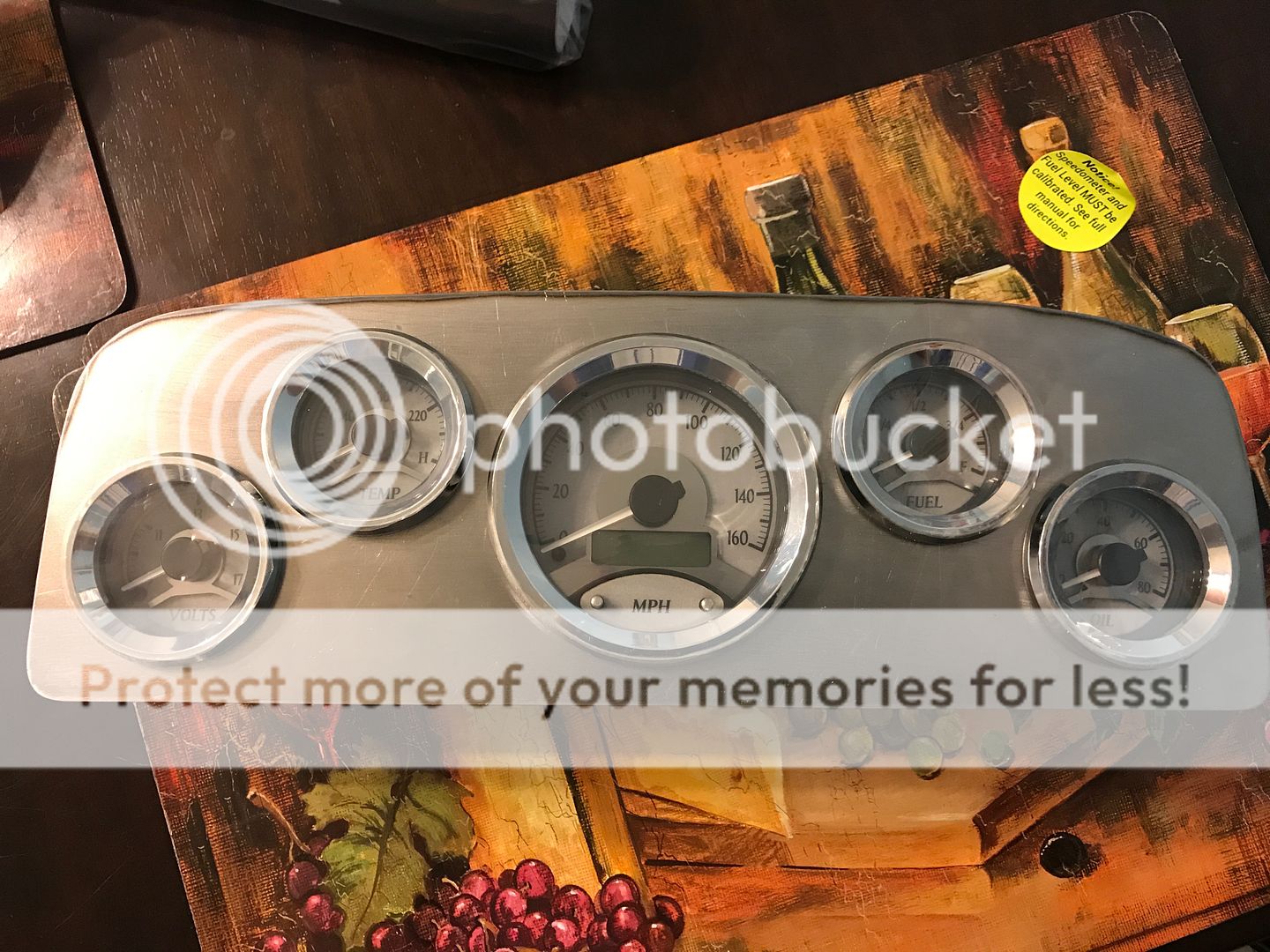
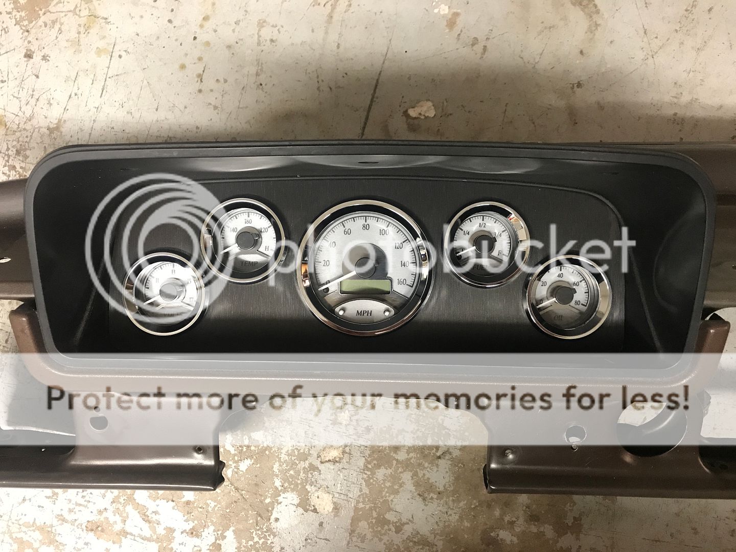
Next up was the dash and gauges. I followed in Lons81's footsteps on this one. He set the bar and I was just trying to get up there to meet expectations. Thanks Lons81. I went with the 5 gauge universal set from Dakota Digital. I arranged the gauges on a computer drawing according to how much (or little) space there was inside the gauge pod. I'll not go into detail about everything I did. I'll just urge you to check out Lons81 build as to how I accomplished everything. Anyway, I started with a printed piece of paper that I glued to a piece of cardboard. I set the gauges in and put the pod on top of it.
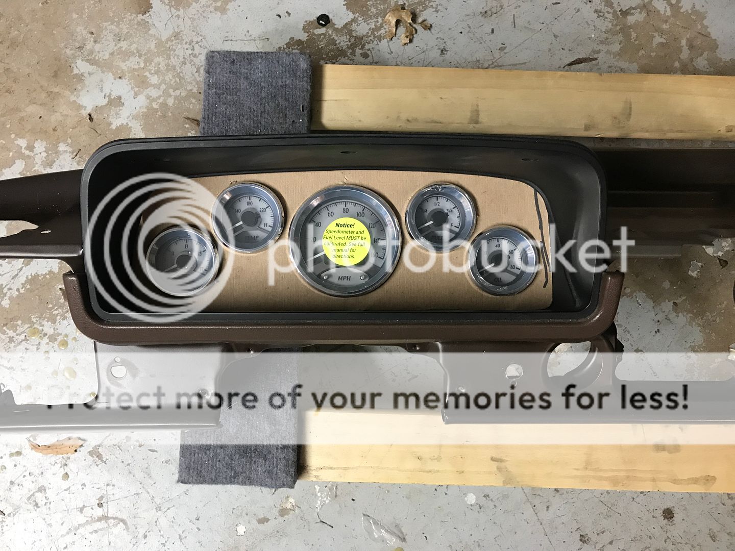
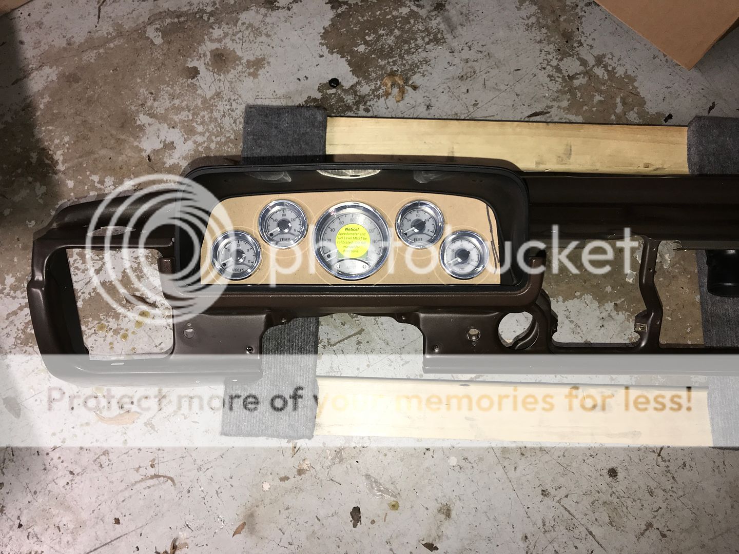
Satisfied, I used that as a template to make one out of 18 gauge sheet metal. I then covered it with a wrap I bought on Amazon. I was trying to get the same gray color that was close to original. It has a brushed look to it though. I think it turned out nice.
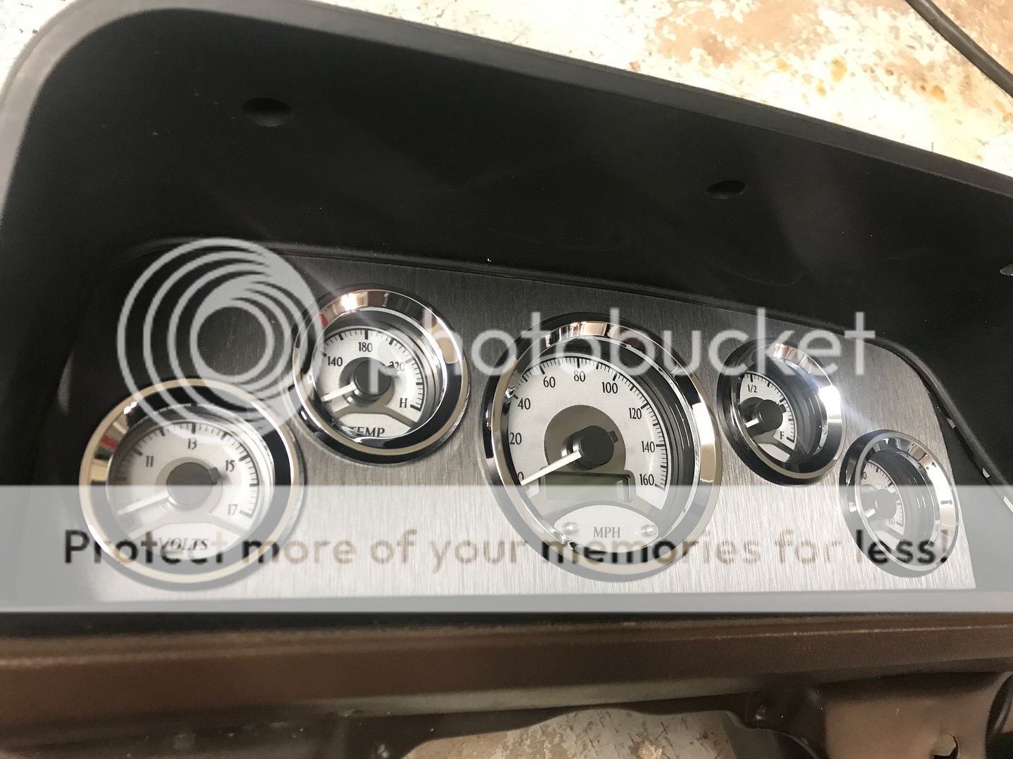
Depending on the angle, it looks darker or lighter.
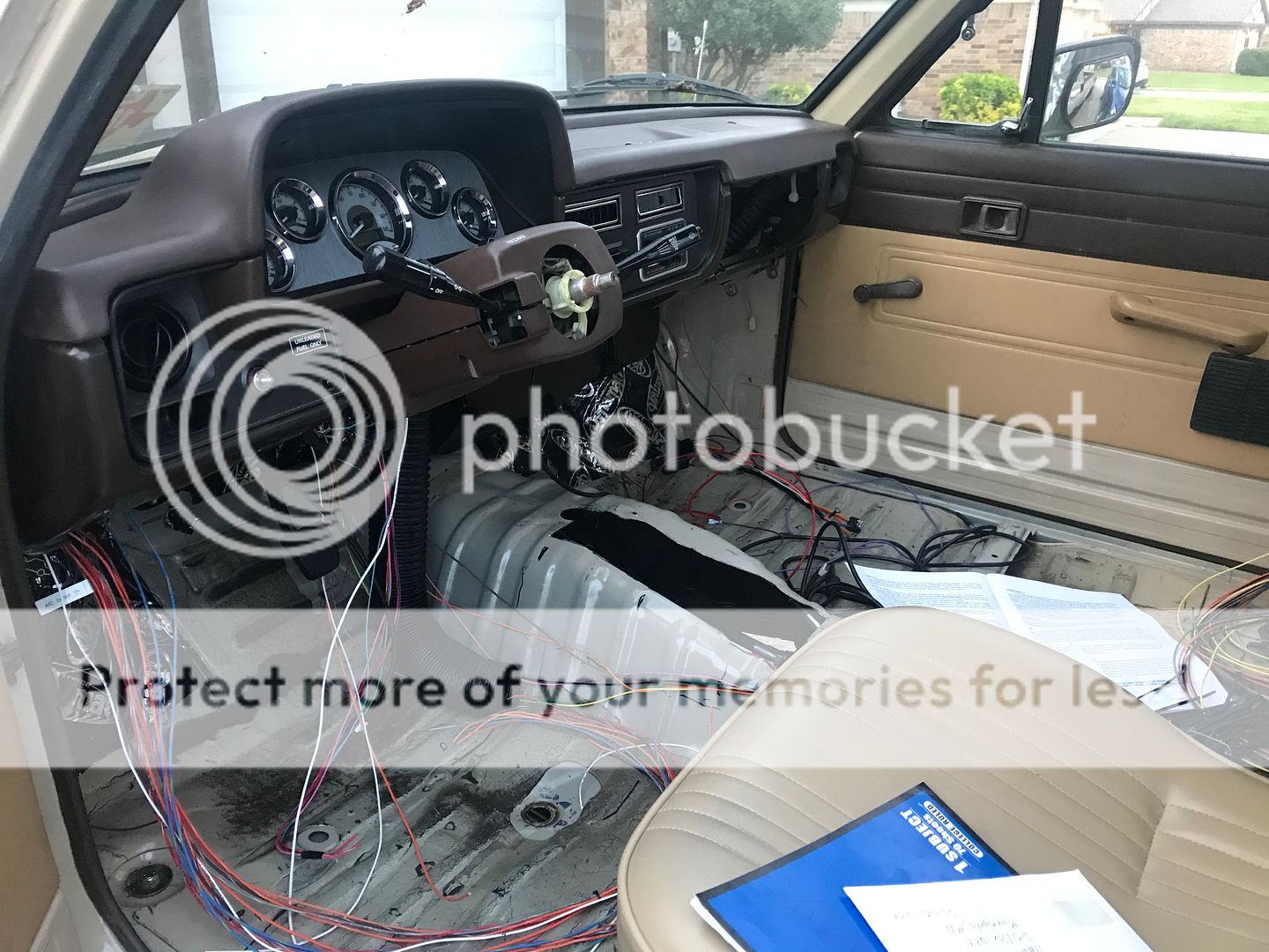
I did the same thing with the console area. I put in two vents at the top and the blue tooth amplifier speaker controller. The Infinity blue tooth amp is a pretty minimal setup. It has an amp under the seat that will have two 6x9 speakers in the doors. It has a low pass out that leads to a second amp/woofer under the driver seat. It's a slick one piece unit from Infinity. An 8" woofer and amp together. It just barely fits under there. I don't listen to music much, but when I do, I like it clear and loud. This system also serves as a hands free system for your cell phone. Bonus. And of course the Vintage Air controller. I like that particular one. It seems early 80ish in design.
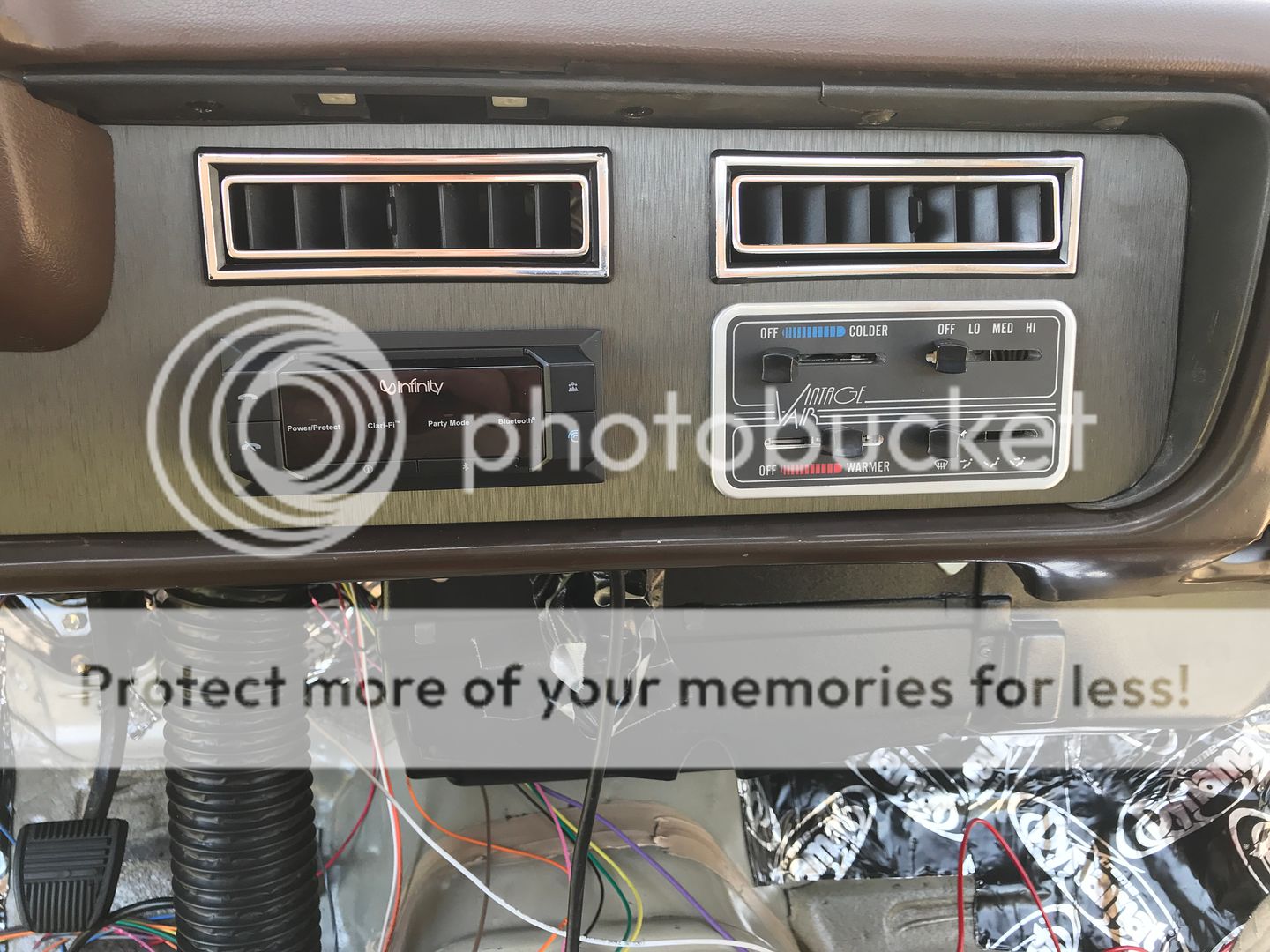
You can see from this photo the gauge background and the console background look different. Its the same wrap.
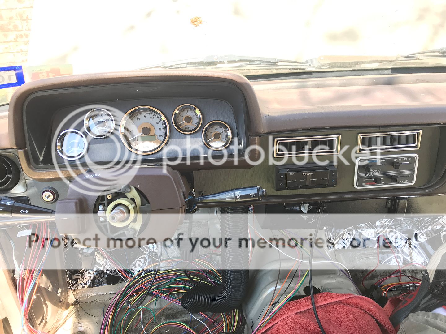
One more pic from the side.


Satisfied, I used that as a template to make one out of 18 gauge sheet metal. I then covered it with a wrap I bought on Amazon. I was trying to get the same gray color that was close to original. It has a brushed look to it though. I think it turned out nice.


Depending on the angle, it looks darker or lighter.

I did the same thing with the console area. I put in two vents at the top and the blue tooth amplifier speaker controller. The Infinity blue tooth amp is a pretty minimal setup. It has an amp under the seat that will have two 6x9 speakers in the doors. It has a low pass out that leads to a second amp/woofer under the driver seat. It's a slick one piece unit from Infinity. An 8" woofer and amp together. It just barely fits under there. I don't listen to music much, but when I do, I like it clear and loud. This system also serves as a hands free system for your cell phone. Bonus. And of course the Vintage Air controller. I like that particular one. It seems early 80ish in design.

You can see from this photo the gauge background and the console background look different. Its the same wrap.

One more pic from the side.
 Jul 14, 2019 | 12:13 PM
#51
Thread Starter
Registered User
Joined: Dec 2017
Posts: 96
Likes: 24
From: Flower Mound, Texas
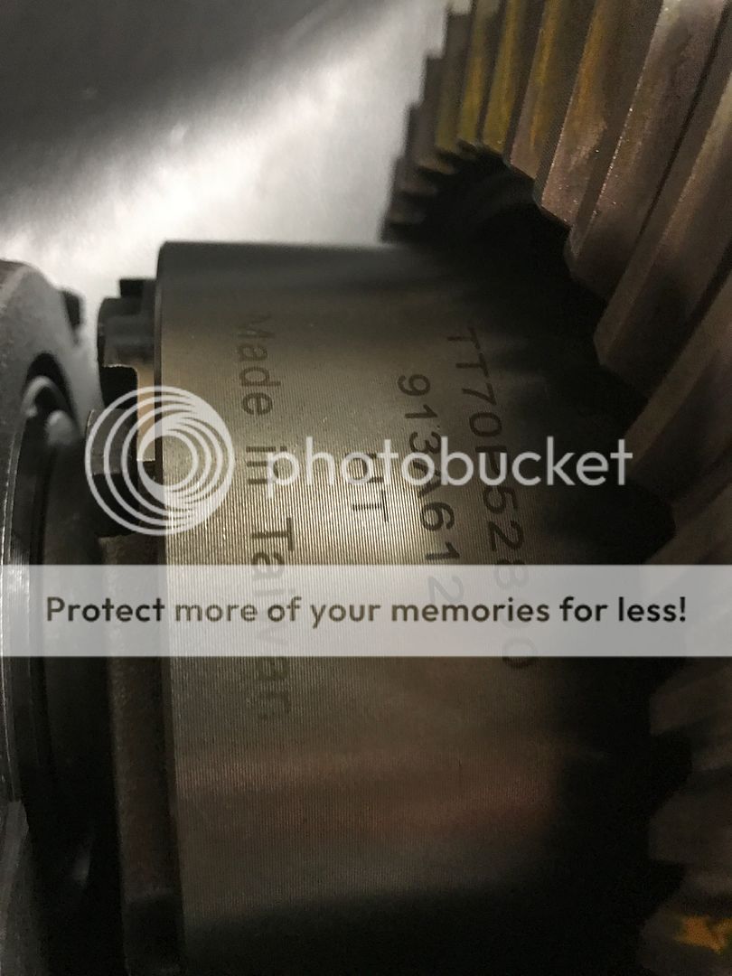
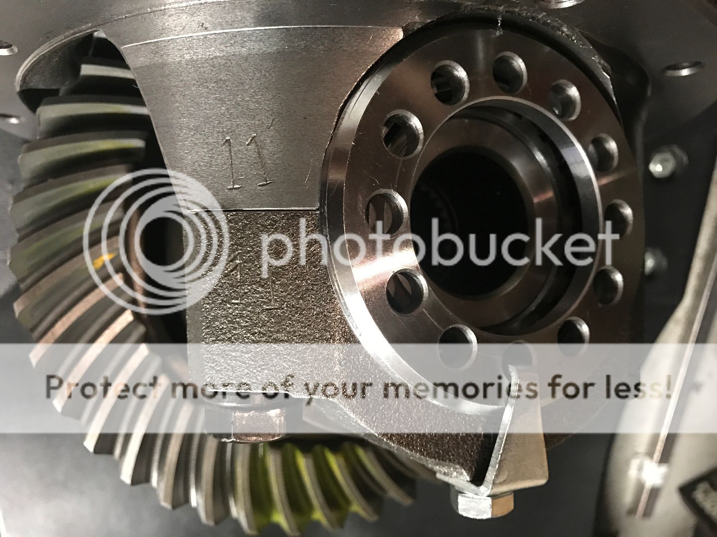
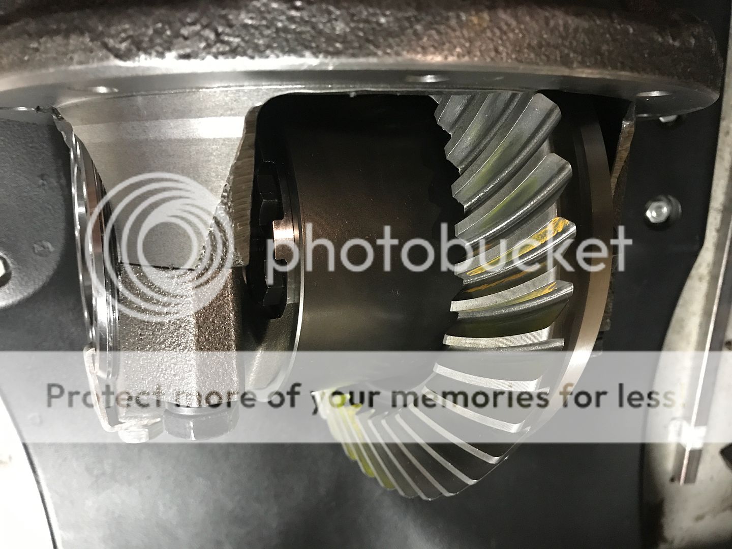
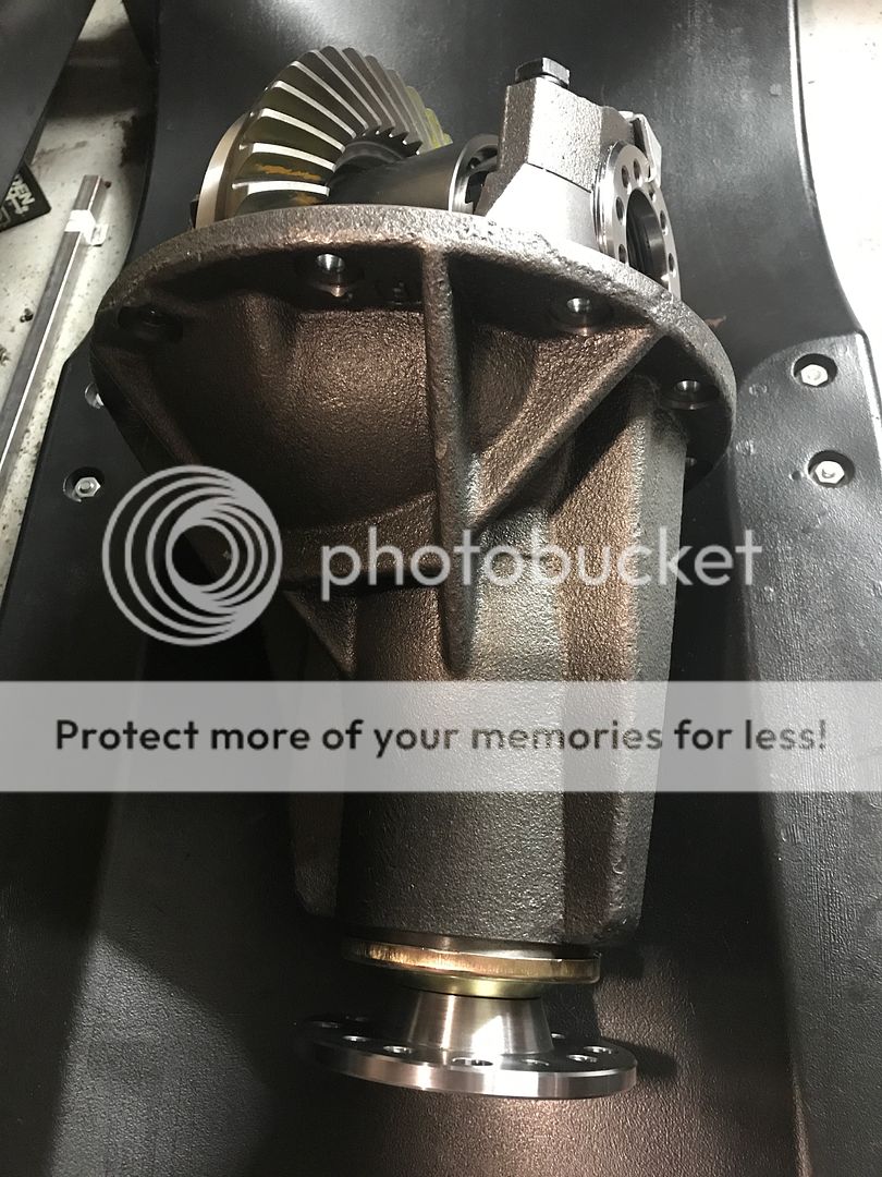
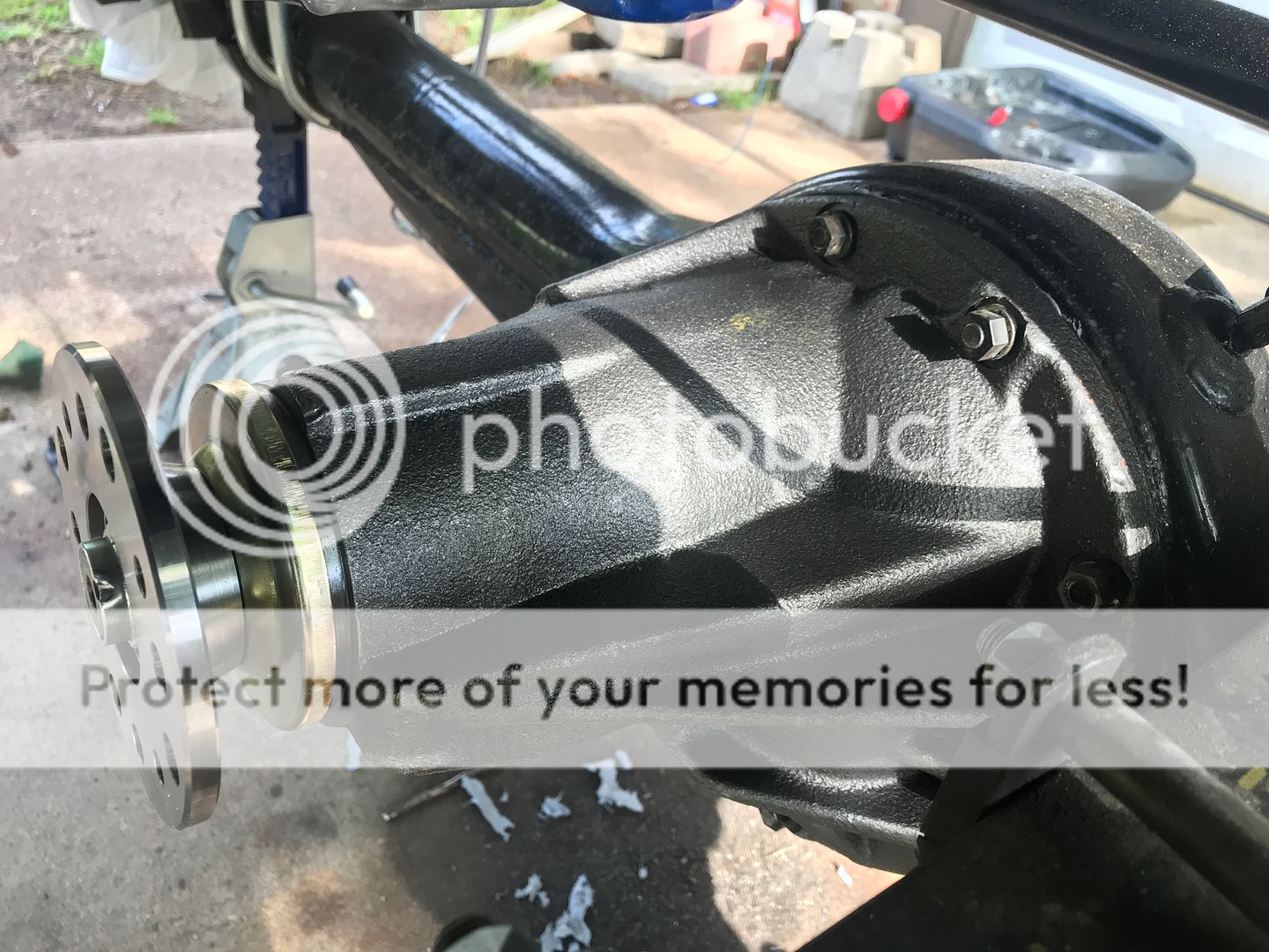
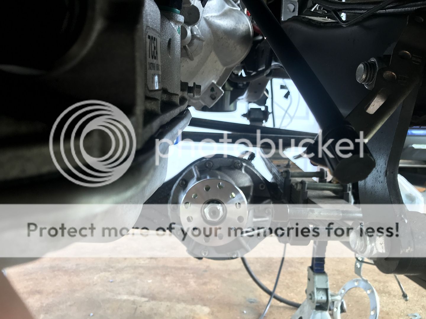
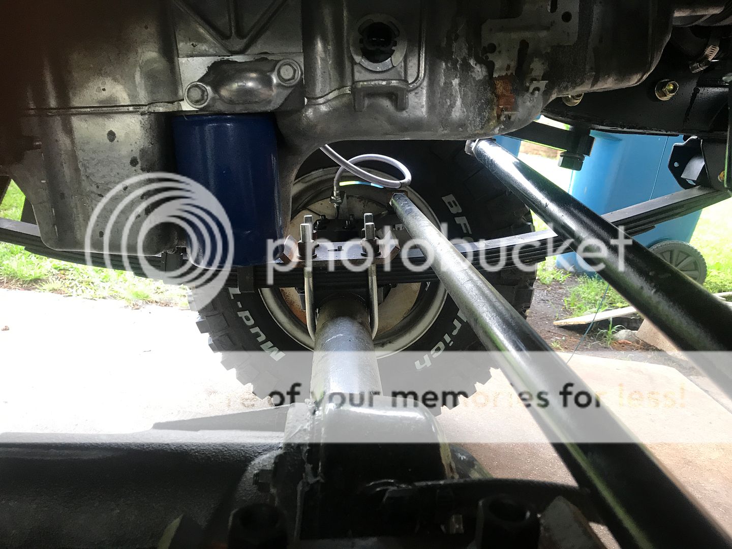
So I started measuring for driveshafts, which lead me to a call to Tom Wood's @ http://www.4xshaft.com. I forgot the gentleman's name (its been a few months now), but he was very helpful and patient. This should really be the last step in any build. You want everything to measure out just as you want it when ready to drive. I didn't have a front bumper or winch on the front, so my angles and stuff would have been off a bit. I'm glad I waited. I ended up doing rear springs up front (future update) to move my axle forward to clear the oil pan. This brought the height up quite a bit. So then, of course, I had to bring up the rear to match it. I know, life is rough. I ended up going with 89-95 rear Toyota springs (if memory serves). So all of that to say, my angles are way different. I need to remeasure and then call Tom Wood's back and let him determine if I need to change my pinion angles, if at all, with leaf wedges. At any rate, we knew right away that my front angles were too steep. What better way to sell myself on a high pinion!?!! A call to Marlin and a lot of money later, a brand new high pinion case with new Eaton TrueTrac with 4.11's was at my door step in a few days.
I was surprised to see the carrier was made in Taiwan.

I was surprised to see the carrier was made in Taiwan.


 Jul 14, 2019 | 12:36 PM
#52
Thread Starter
Registered User
Joined: Dec 2017
Posts: 96
Likes: 24
From: Flower Mound, Texas
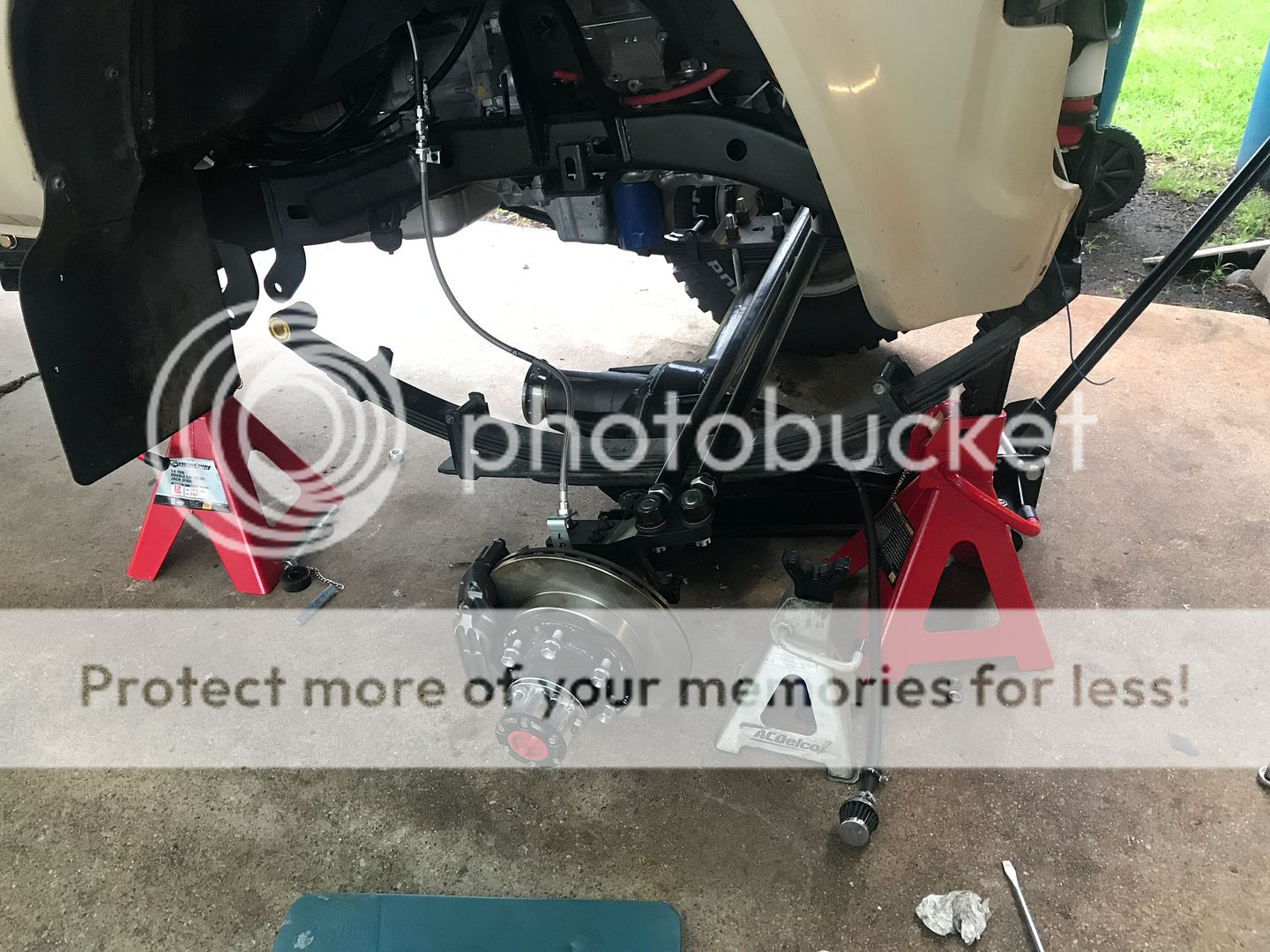
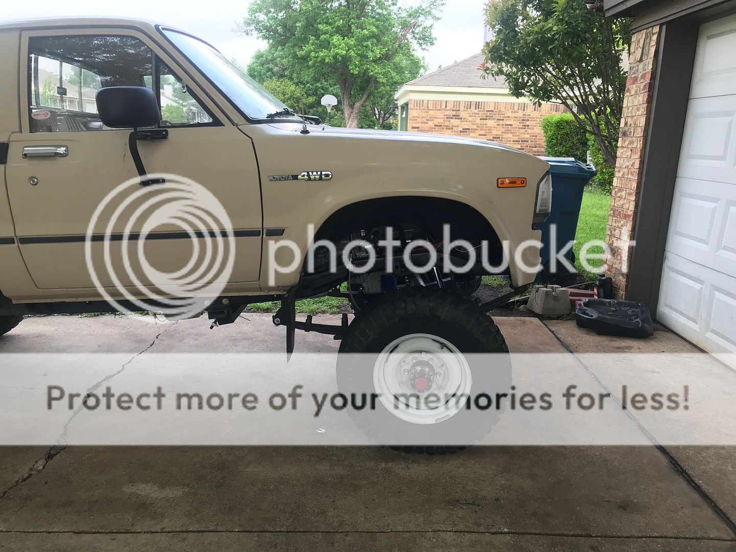
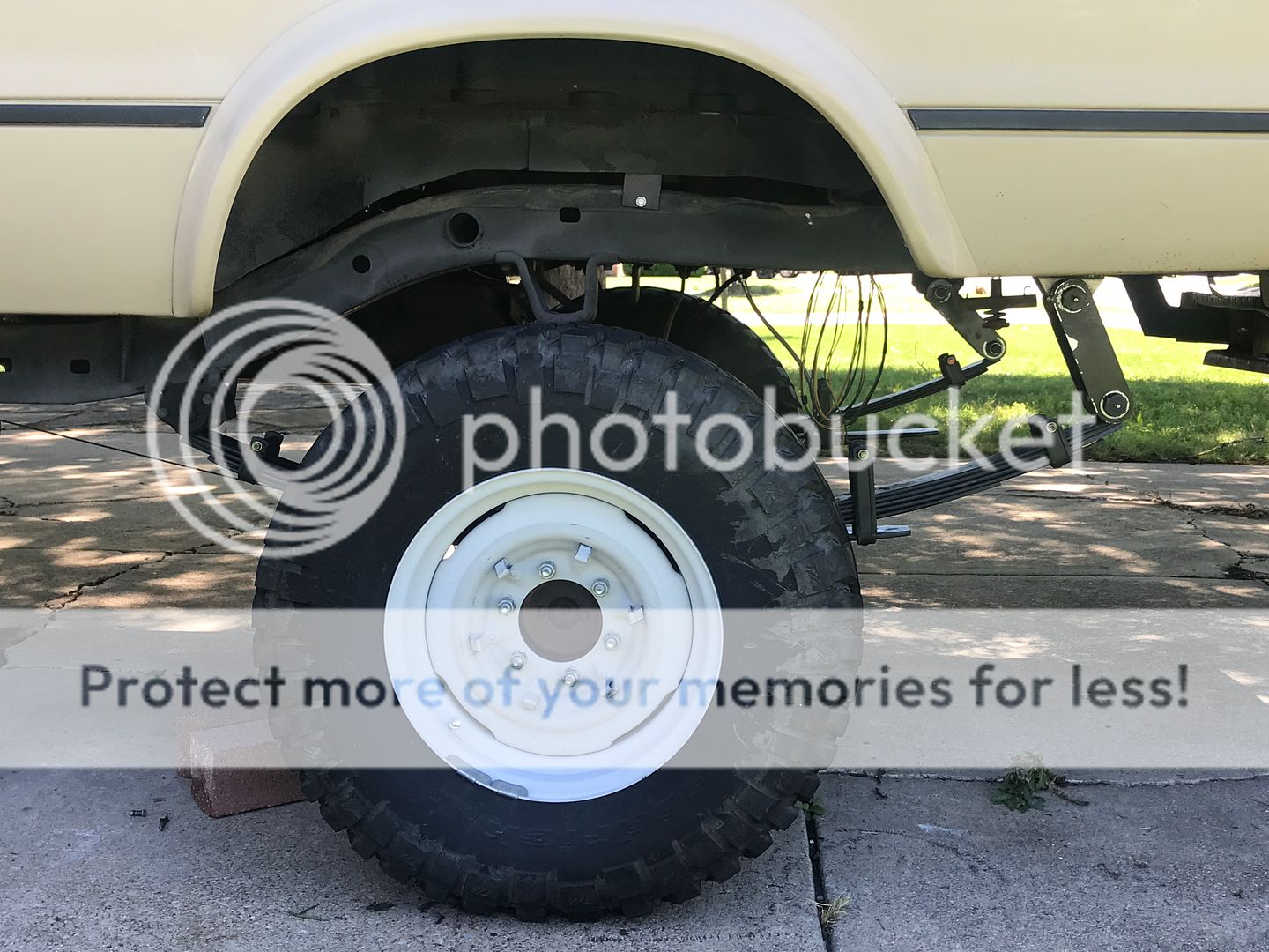
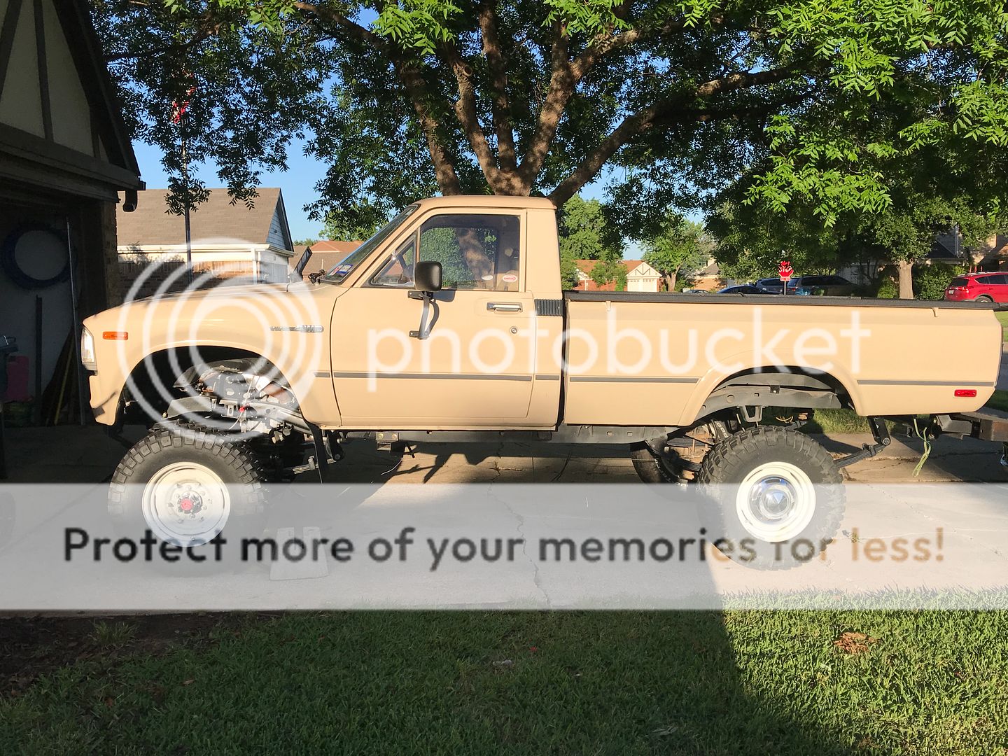
I guess I'll tackle the suspension now. All of my springs are OME. I started with the correct year OME springs for my 1982. I moved the rear springs up front and ordered the CS019r's for the rear. I should have ordered the CS020's. I ended up getting an add-a-leaf to throw into the pack. I removed one or two of the overflew springs. I can't remember all of the changing I did. I pulled the springs on the front and rear and added and took away leafs until I was satisfied. That took about two weeks worth of evenings a a couple of days off. What a pain. It might end up being a little stiff, but I can pull a spring from each spring all the way around if I need to. As you will see, I'll need bigger tires. I know, life is rough! I'm thinking Super Swampers in 34x10.5x15. After putting the new rear springs on, it was evident that I'd have to move the spring shackle. I ordered up some from Marlin and cut the old ones off. I moved them about 1.5" to the rear.
Bad angle
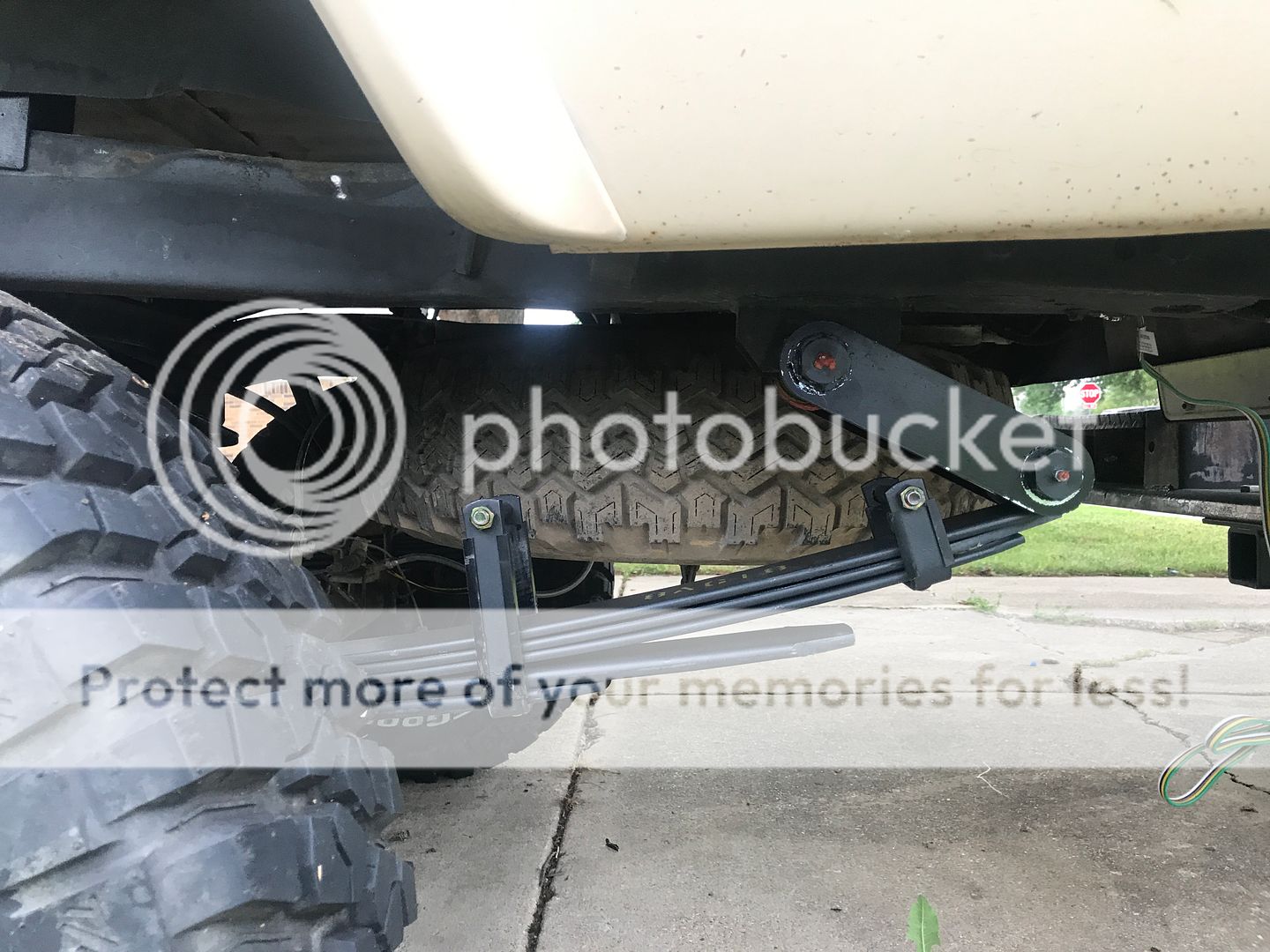
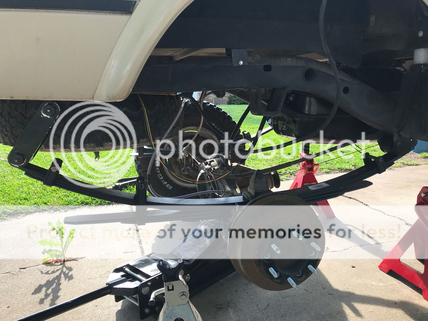
Driver side, rear finished
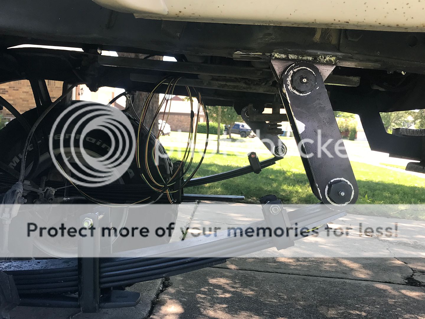
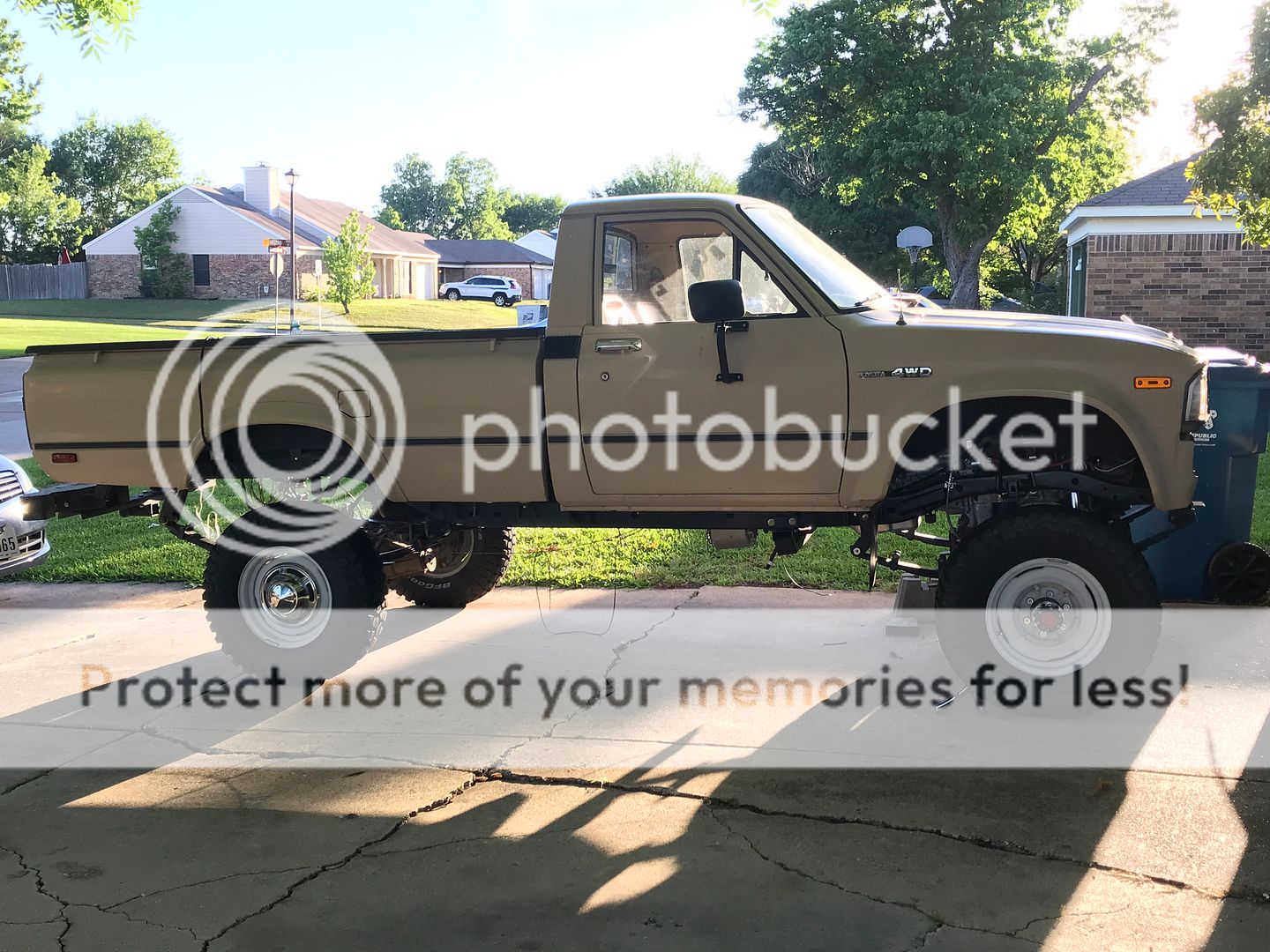
The front came down a little after getting a bumper and winch back on. I'm still not happy with the stance, but I'll work on it more after its running.
Bad angle


Driver side, rear finished


The front came down a little after getting a bumper and winch back on. I'm still not happy with the stance, but I'll work on it more after its running.
 Jul 14, 2019 | 01:06 PM
#53
Thread Starter
Registered User
Joined: Dec 2017
Posts: 96
Likes: 24
From: Flower Mound, Texas
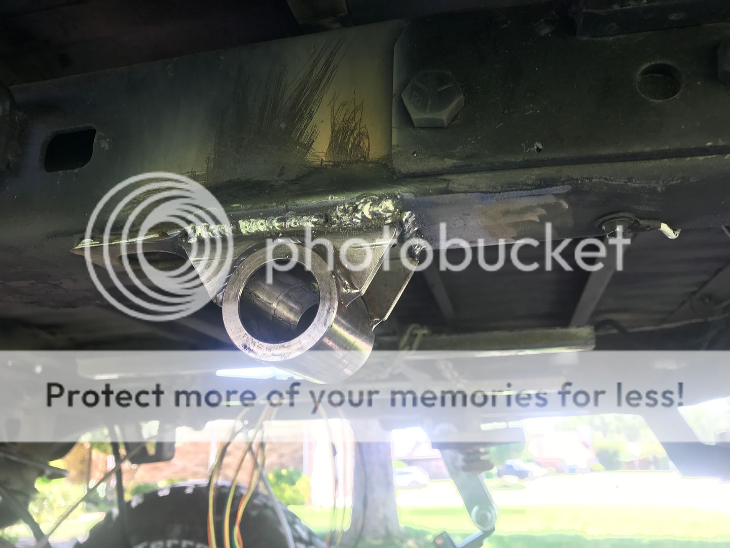
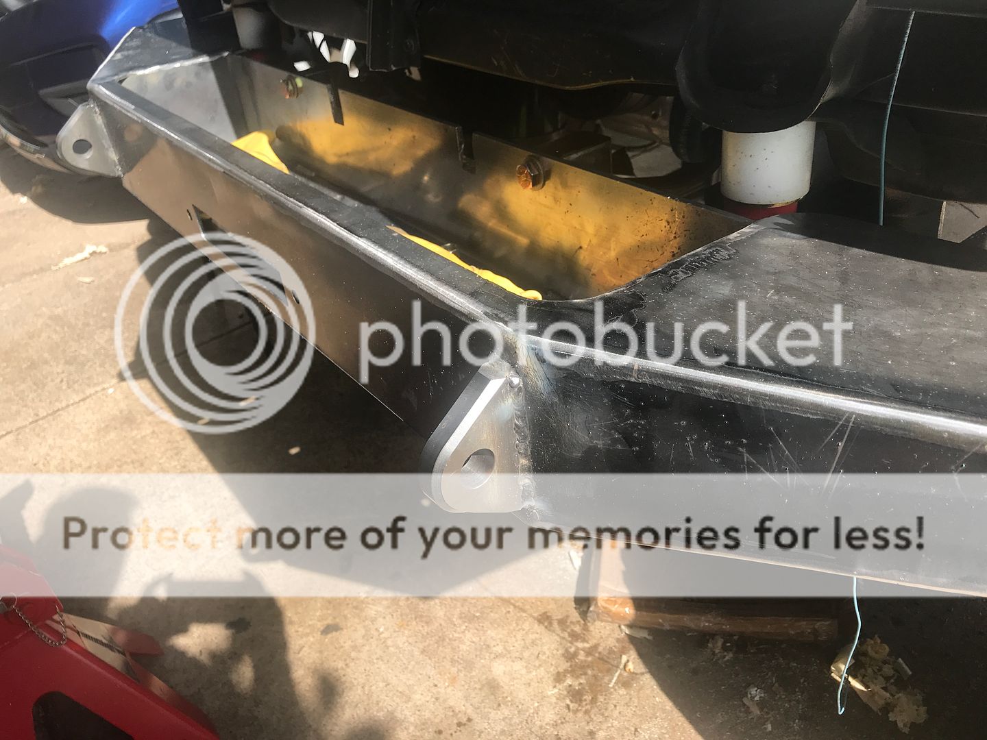
Bumper time! I found this kit online and then cheaper on an eBay auction. https://www.jcroffroad.com/product/DIY-XJ-F-WN.html. It's for an older Jeep SUV. It's a pretty simple kit that I could modify to fit my truck.
I started with this

Cut off the original bumper mounting tabs
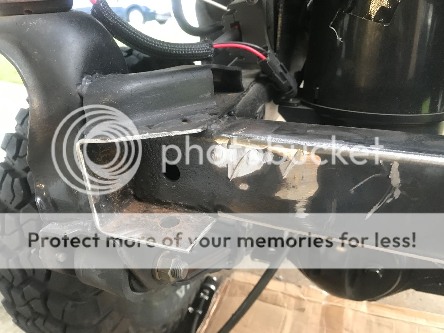
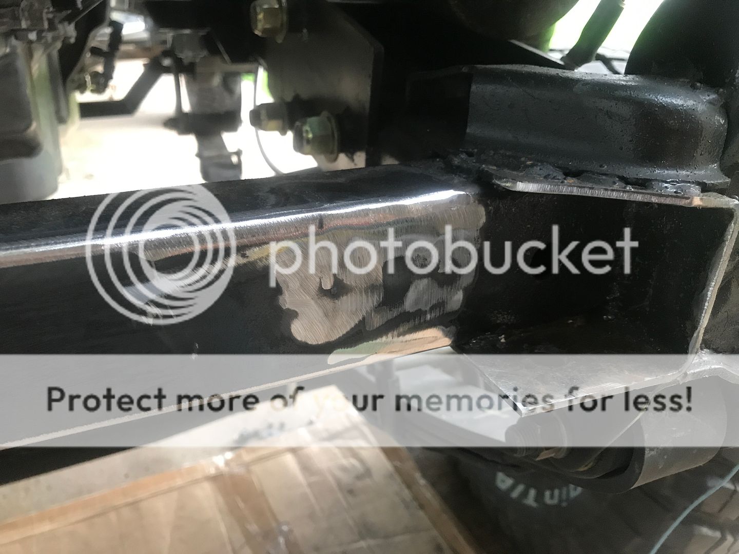
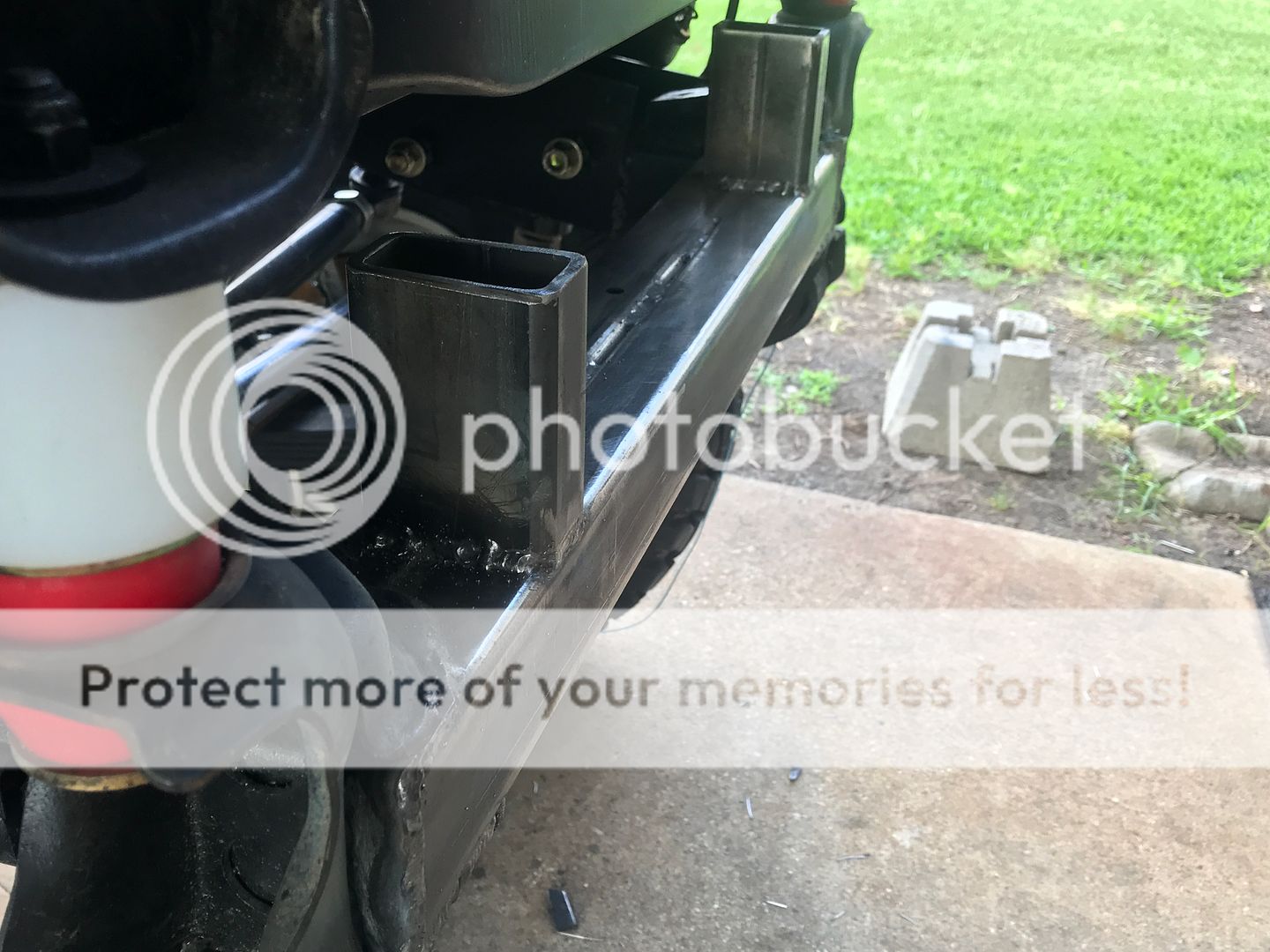
Found a piece of 1.5" x 2.5" x 3/16" thick rectangle tubing on ebay to well in to the "pockets" of the frame end. This made everything flush.
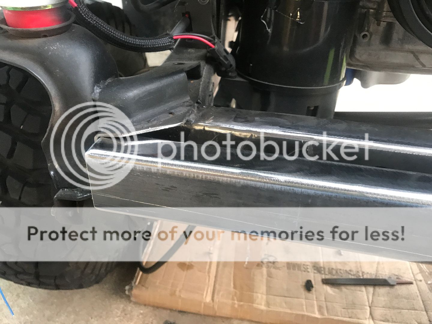
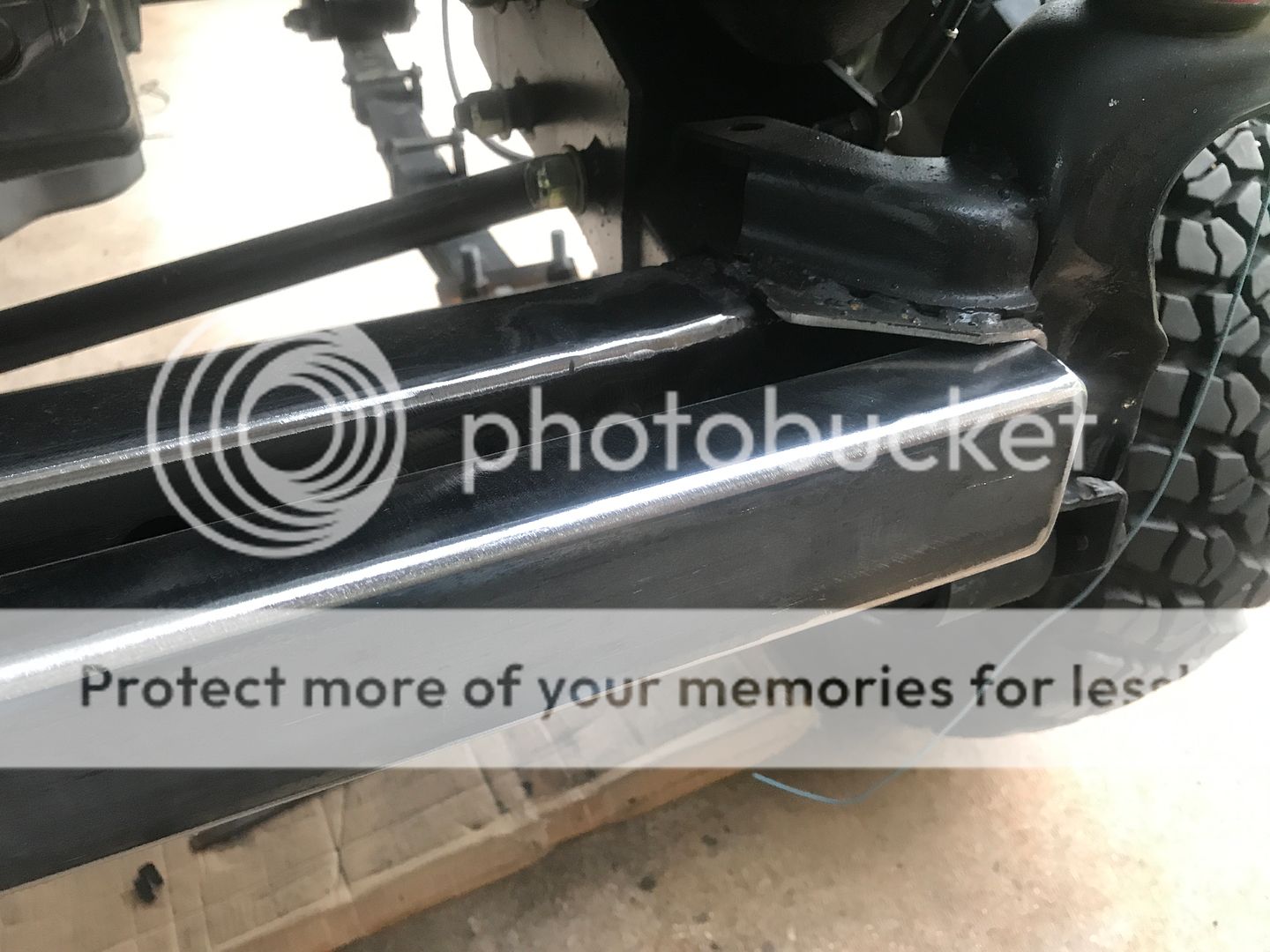
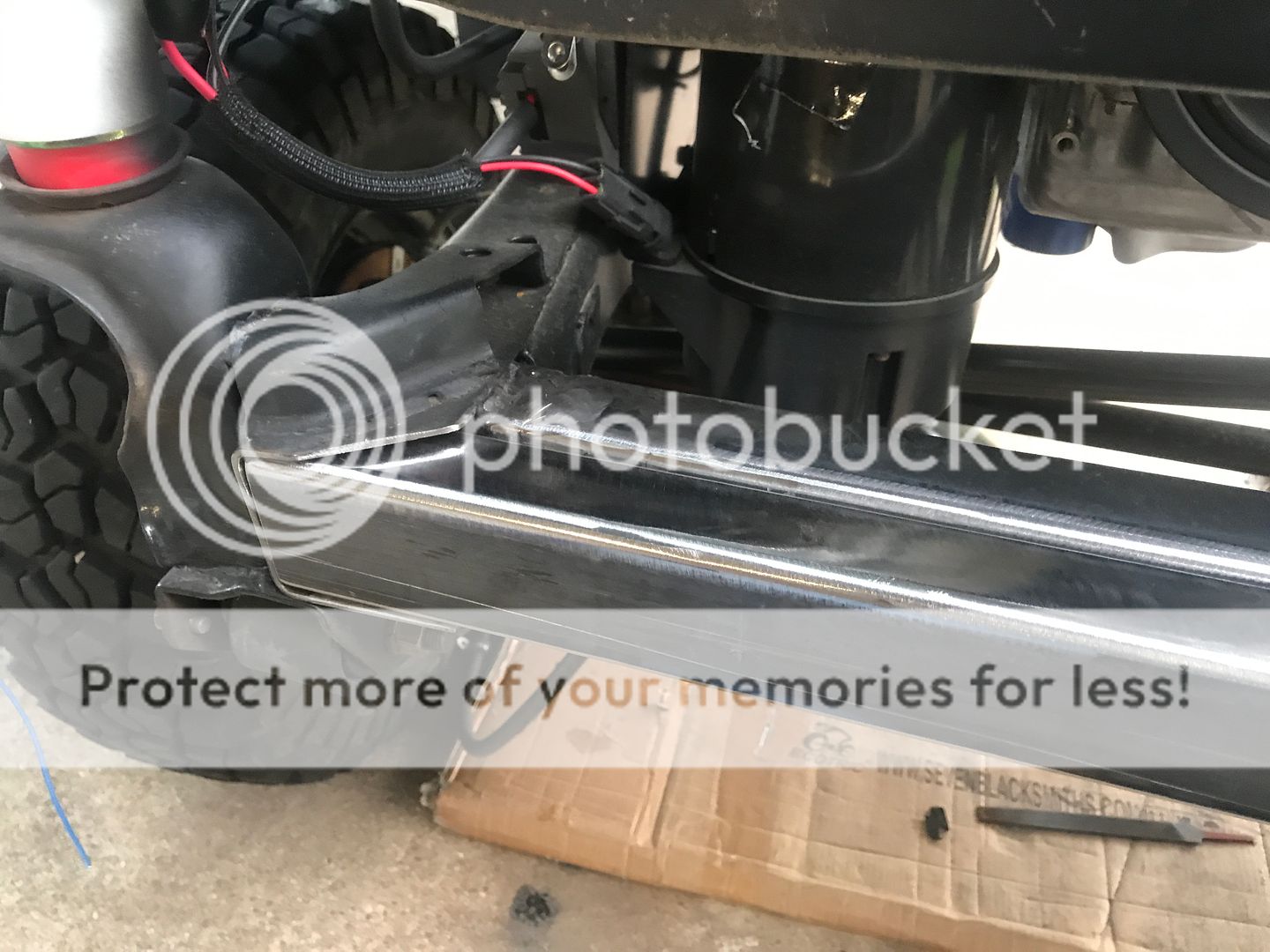
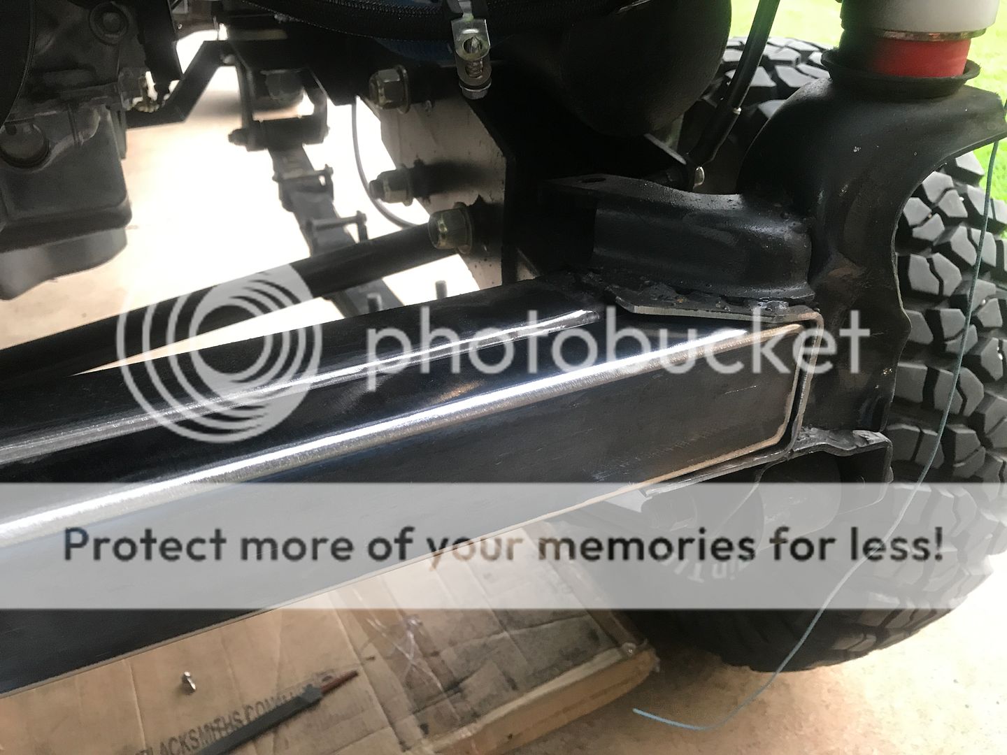
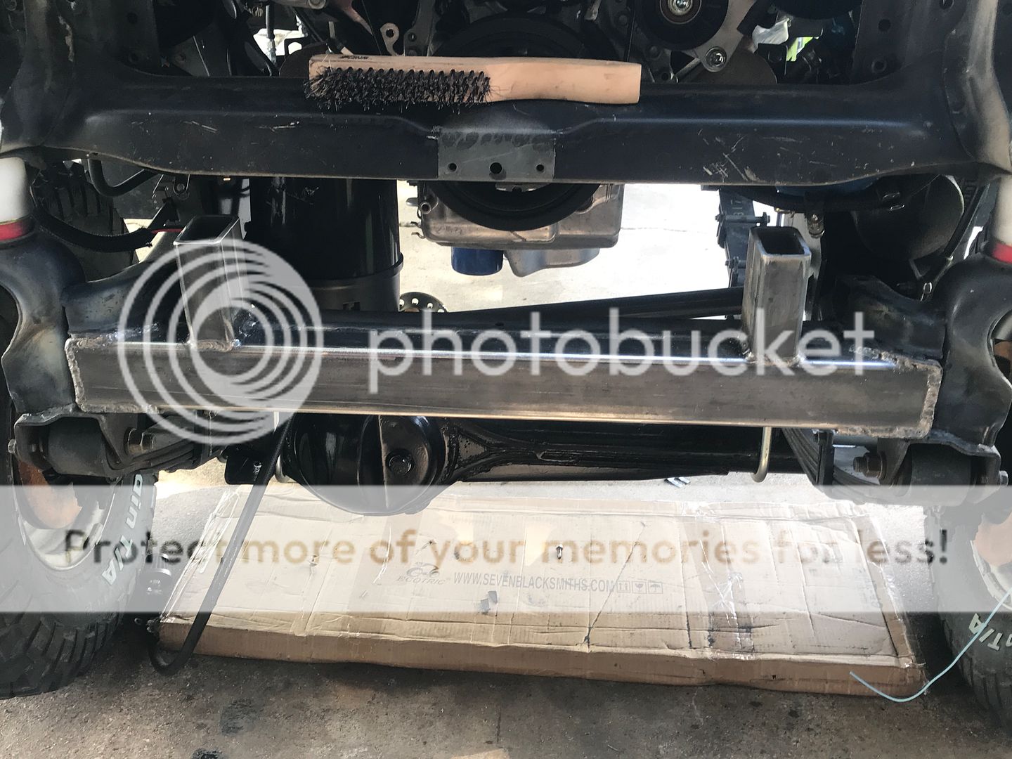
I tack welded that in and then used the left over piece to make some vertical mounting surfaces, which I tack welded to the top of the piece I had previously tack welded
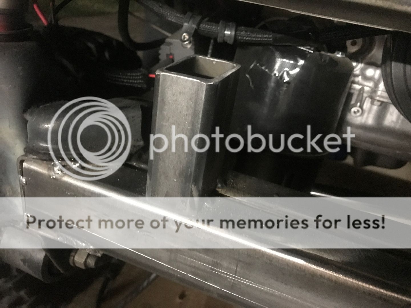
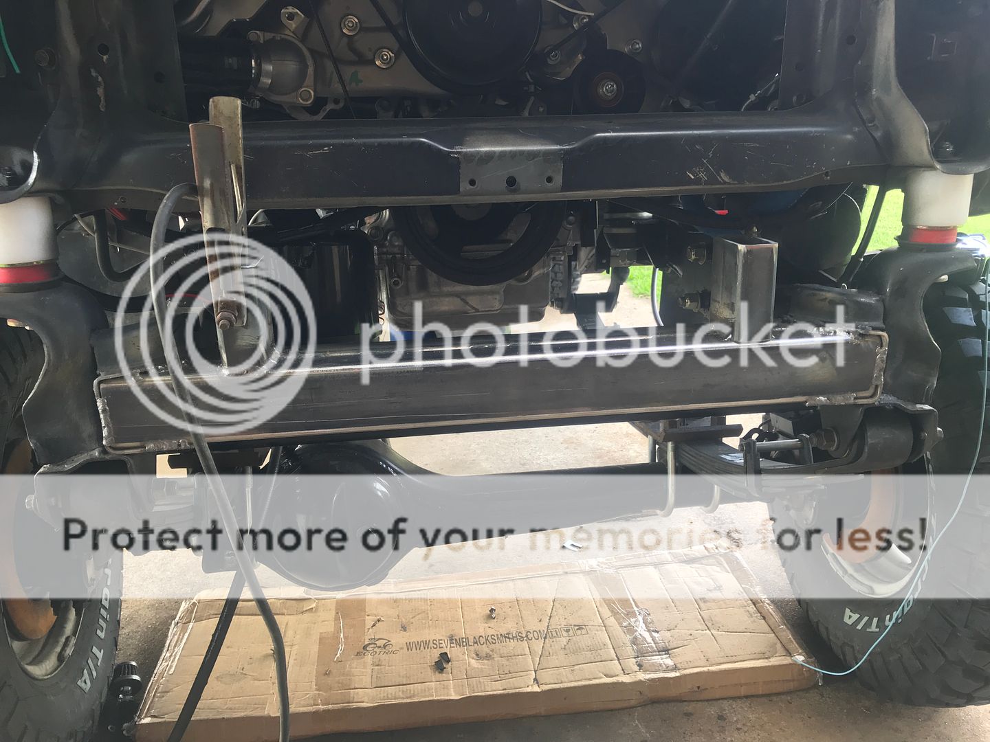
After I was satisfied, I finished welding everything up. It is damned solid
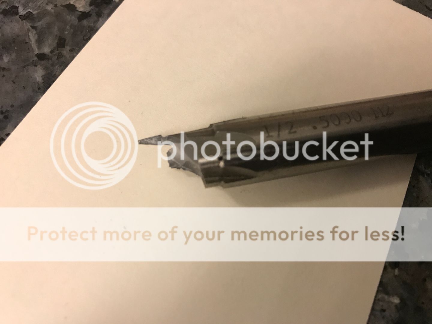
A quick word of caution: this is what's left of a .500" reamer! Always wear safety goggles. Even if you use the "shut your eyes while drilling" method, if a piece of this hit your eye it would go right through your eye lid. It shattered and flew in a thousand different directions. Those edges are razor sharp.
I'm not going to give a tutorial on how I welded this bumper up. There are some videos on youtube that show this very bumper being tabbed up. I tacked everything and drilled mounting holes for 1/2" bolts in the bumper supports I welded onto the end of the frame.
I didn't like the shackle mounts that came with the kit. They were really rough. Like cut out of plate with a plasma torch rough. I found these on eBay and welded them in instead.
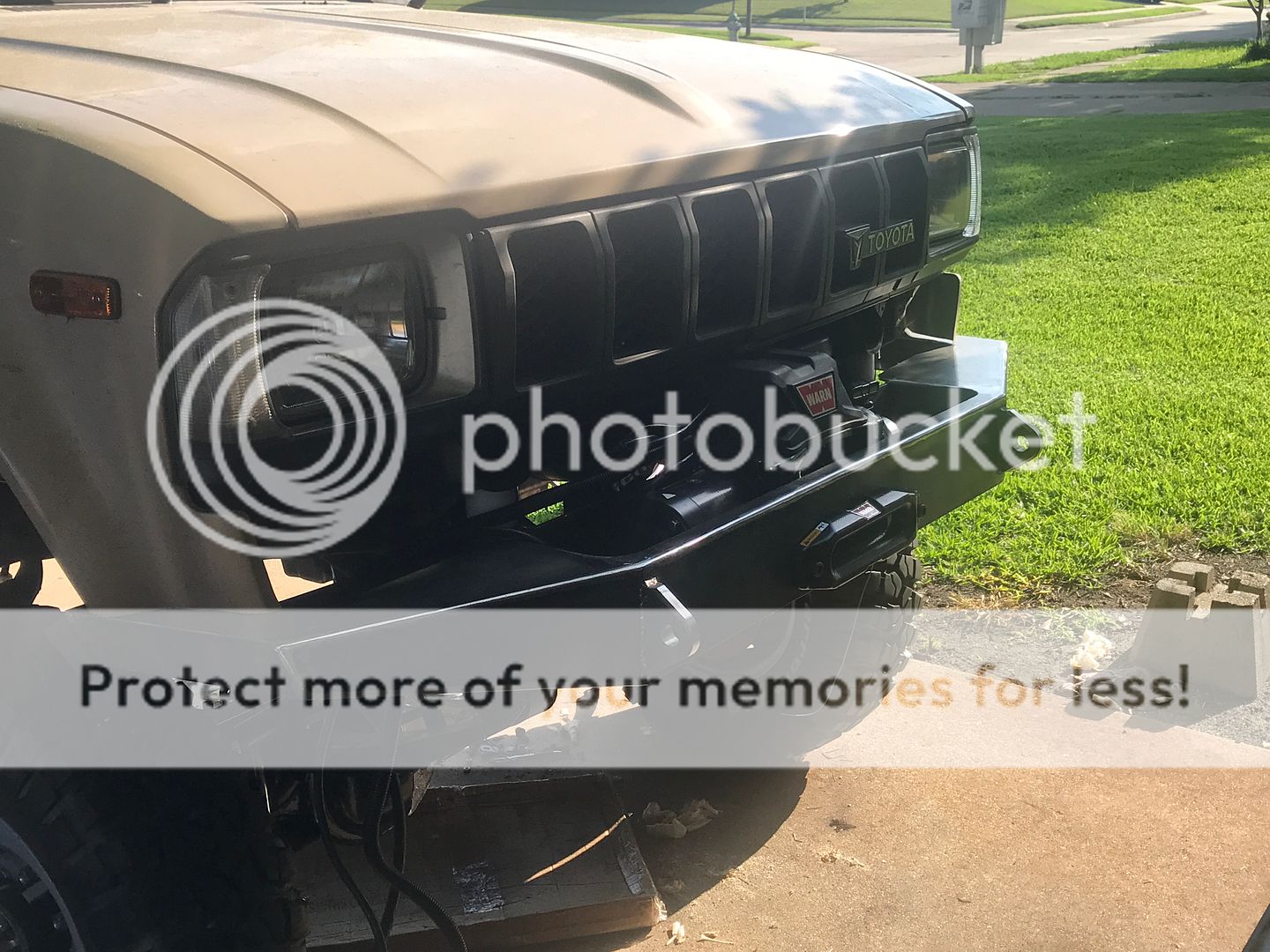
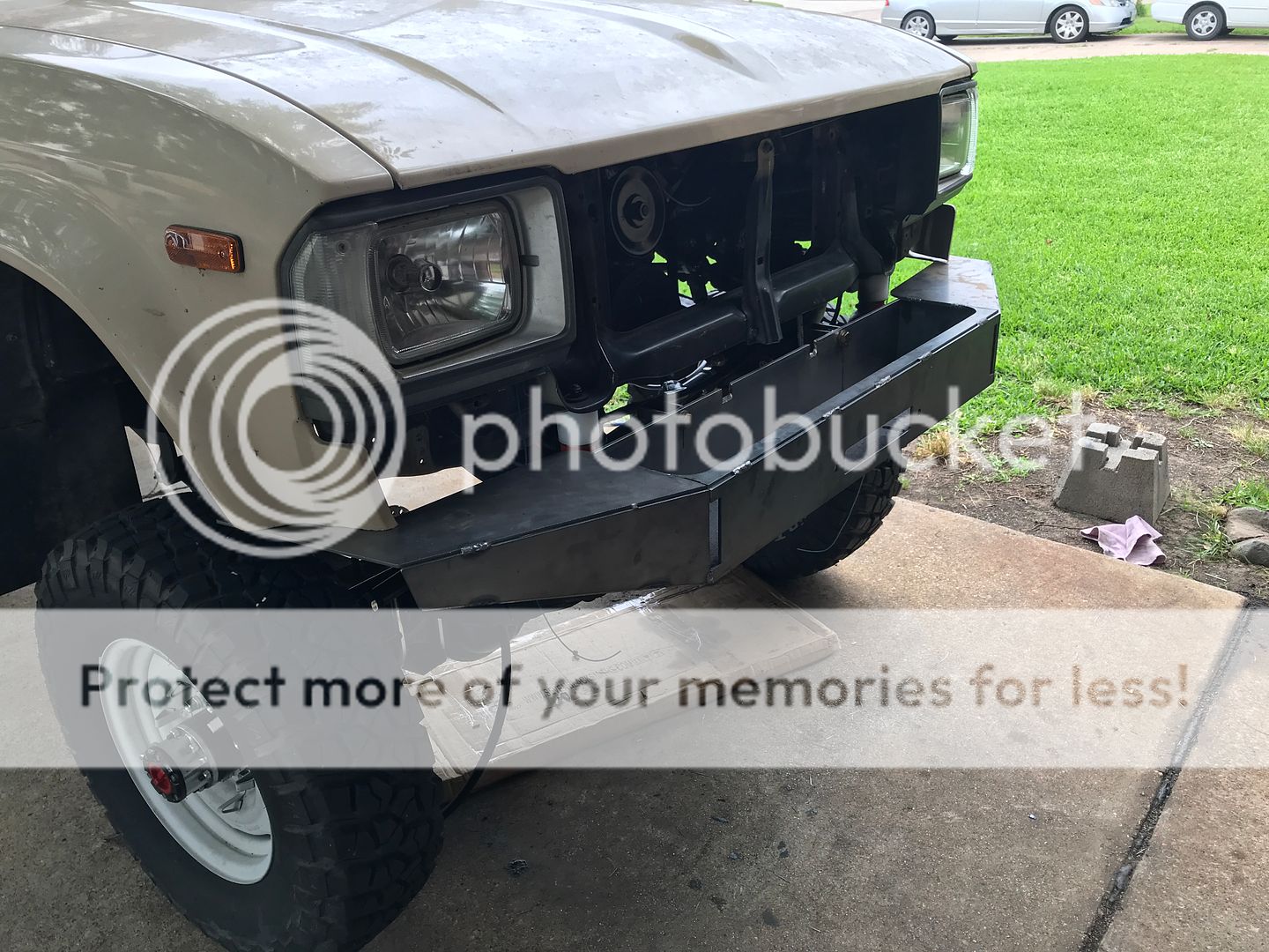
With some paint
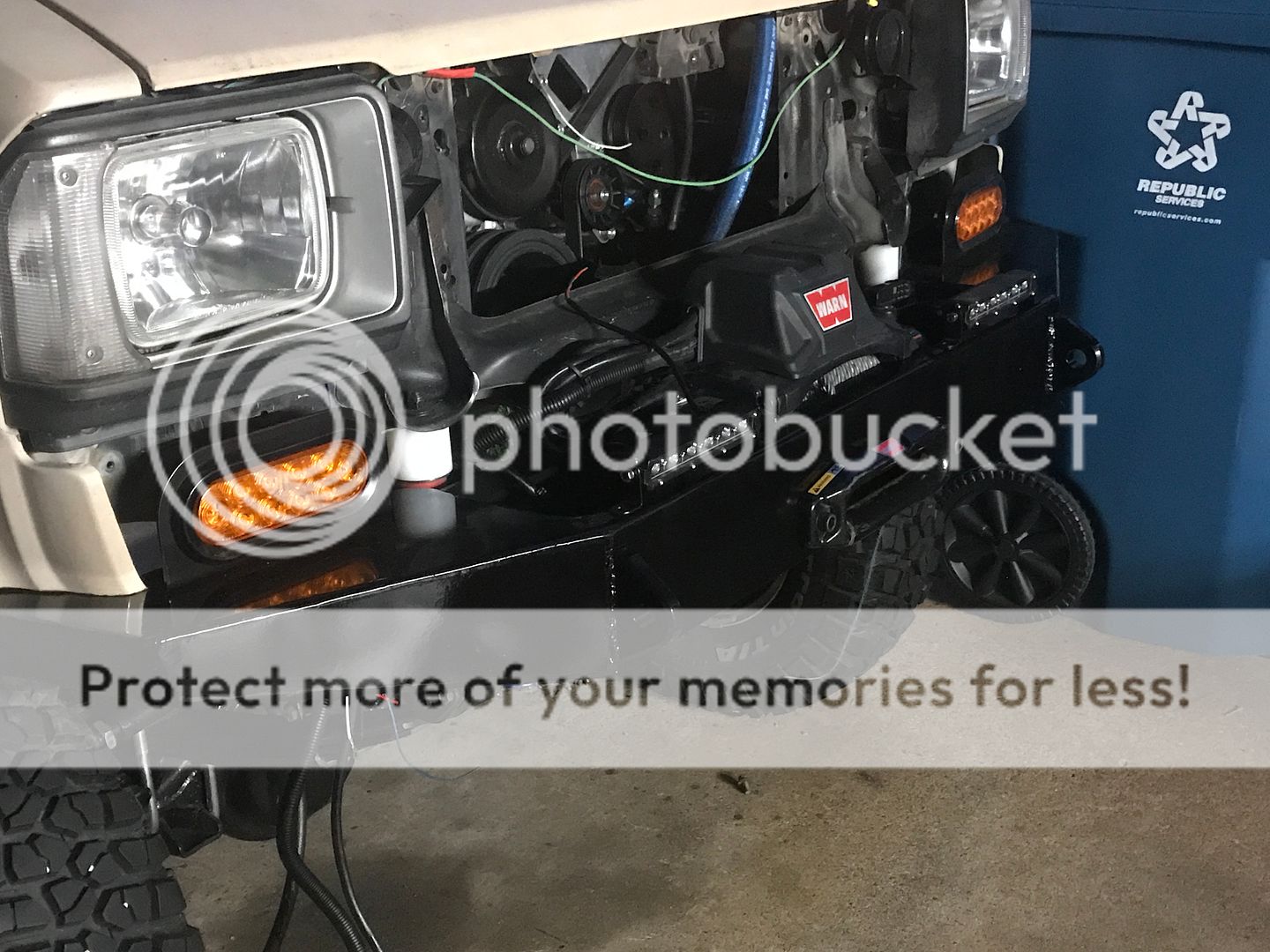
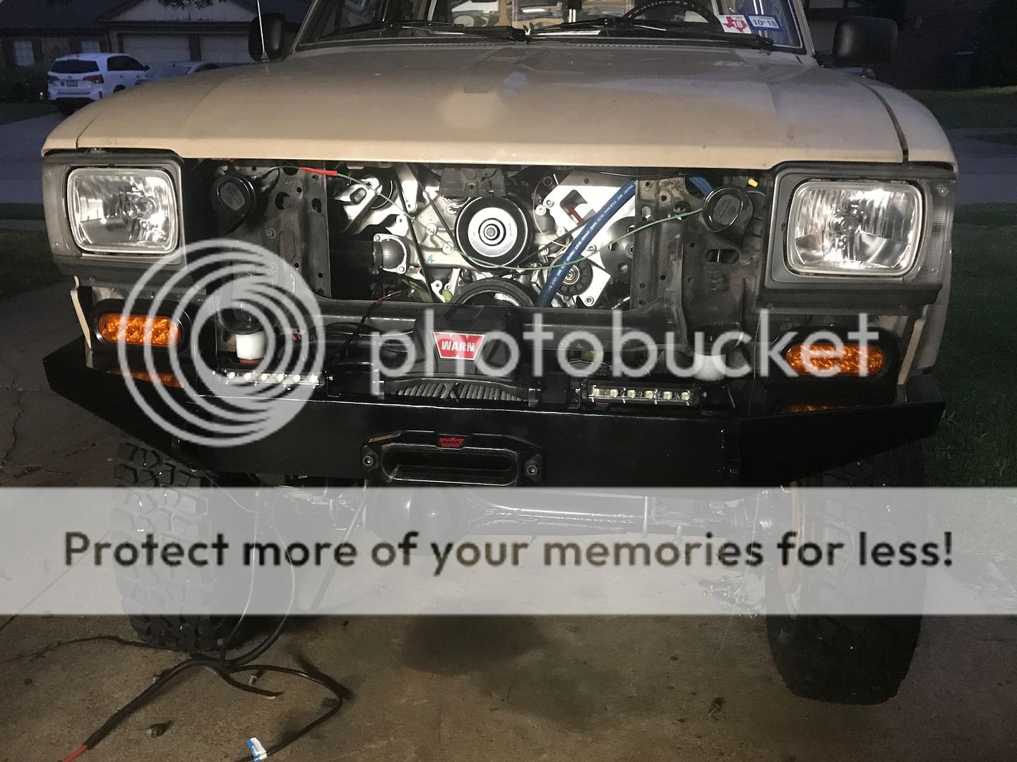
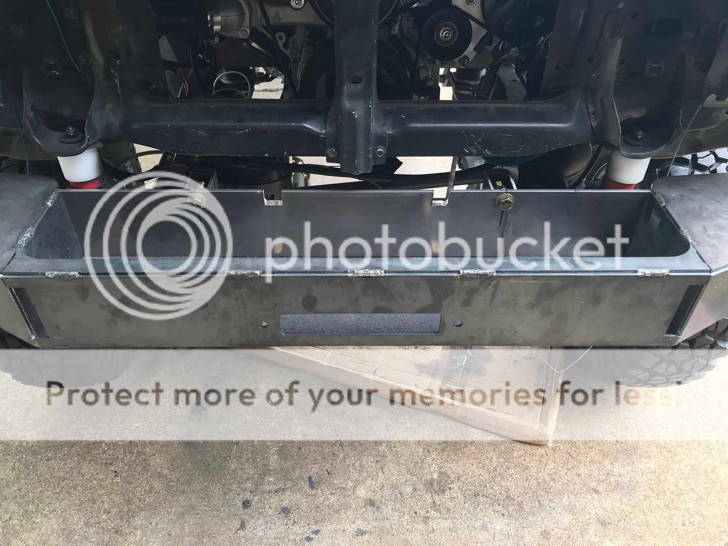
Some bracing on the bottom that ties it into the frame at another point. It bolts into the same hole as the original rock guard location. I lifted the entire front of the truck with a hi-lift jack and this bumper didn't budge. Later I'm going to weld a 3/16" plate to the angled part of these braces for a rock guard. I'm also thinking about mounting the A/C condenser behind it at an angle with a separate electric fan. I'll have o measure once it's on there to find out if it will fit.
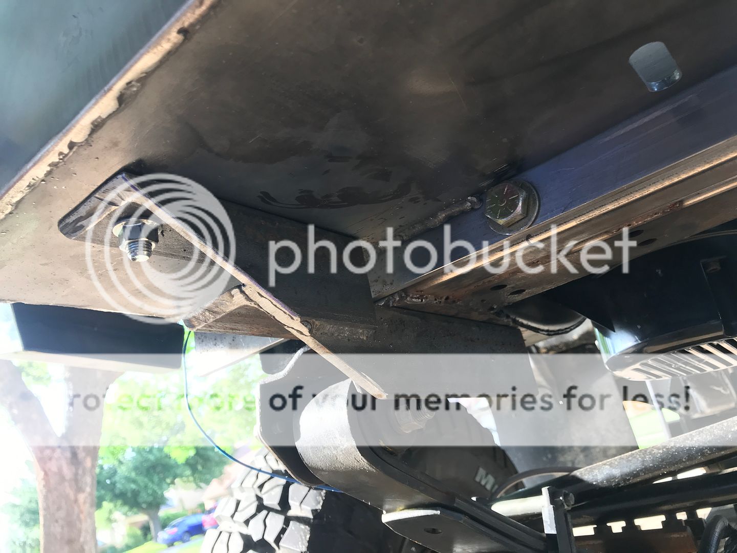
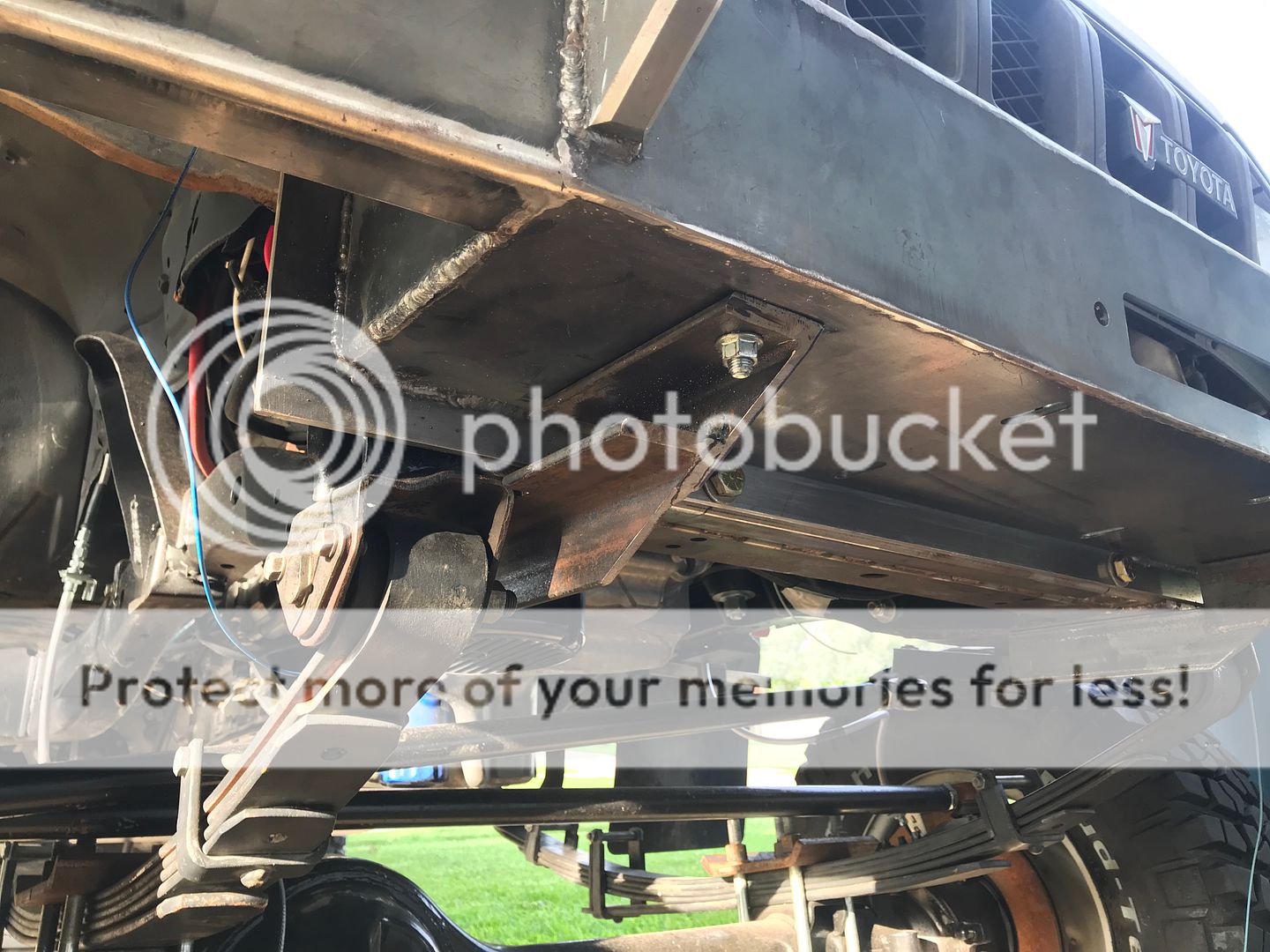
There are a total of (6) 1/2" hardened bolts holding this bumper on.
I started with this

Cut off the original bumper mounting tabs


Found a piece of 1.5" x 2.5" x 3/16" thick rectangle tubing on ebay to well in to the "pockets" of the frame end. This made everything flush.


I tack welded that in and then used the left over piece to make some vertical mounting surfaces, which I tack welded to the top of the piece I had previously tack welded


After I was satisfied, I finished welding everything up. It is damned solid


A quick word of caution: this is what's left of a .500" reamer! Always wear safety goggles. Even if you use the "shut your eyes while drilling" method, if a piece of this hit your eye it would go right through your eye lid. It shattered and flew in a thousand different directions. Those edges are razor sharp.

I'm not going to give a tutorial on how I welded this bumper up. There are some videos on youtube that show this very bumper being tabbed up. I tacked everything and drilled mounting holes for 1/2" bolts in the bumper supports I welded onto the end of the frame.


I didn't like the shackle mounts that came with the kit. They were really rough. Like cut out of plate with a plasma torch rough. I found these on eBay and welded them in instead.


With some paint


Some bracing on the bottom that ties it into the frame at another point. It bolts into the same hole as the original rock guard location. I lifted the entire front of the truck with a hi-lift jack and this bumper didn't budge. Later I'm going to weld a 3/16" plate to the angled part of these braces for a rock guard. I'm also thinking about mounting the A/C condenser behind it at an angle with a separate electric fan. I'll have o measure once it's on there to find out if it will fit.


There are a total of (6) 1/2" hardened bolts holding this bumper on.
Jul 16, 2019 | 07:56 AM
#57
I'm still working through the pain and setbacks from shoulder surgery, thanks for asking. May have to have a third surgery to fix it all. At 75, we old dudes don't heal so fast
 Jul 16, 2019 | 10:11 AM
#58
Thread Starter
Registered User
Joined: Dec 2017
Posts: 96
Likes: 24
From: Flower Mound, Texas
Thanks Bump530! It was difficult to cut up a perfectly good gauge pod, but at some point you have to throw caution to the wind and trust your planning. That’s what I did anyway. If you are decent with fabricating it’ll be a piece of cake. I dislike fab work. When somethings not turning out the way I planned I’ll just put it down until a solution presents itself. Sometimes that weeks!
Lons81, 75! I feel old at 47, lol. You’ll get there. I hope you won’t need a 3rd surgery.
Lons81, 75! I feel old at 47, lol. You’ll get there. I hope you won’t need a 3rd surgery.
 Jul 29, 2019 | 08:03 PM
#60
Thread Starter
Registered User
Joined: Dec 2017
Posts: 96
Likes: 24
From: Flower Mound, Texas
FDXMD11C, I do have some things to update, its just finding the time to actually write this stuff up has been difficult lately. Lots of irons in the fire around here.
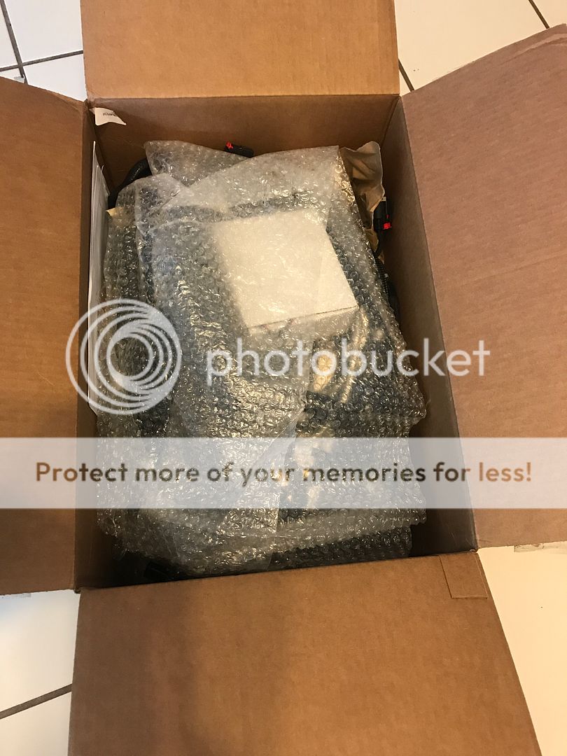
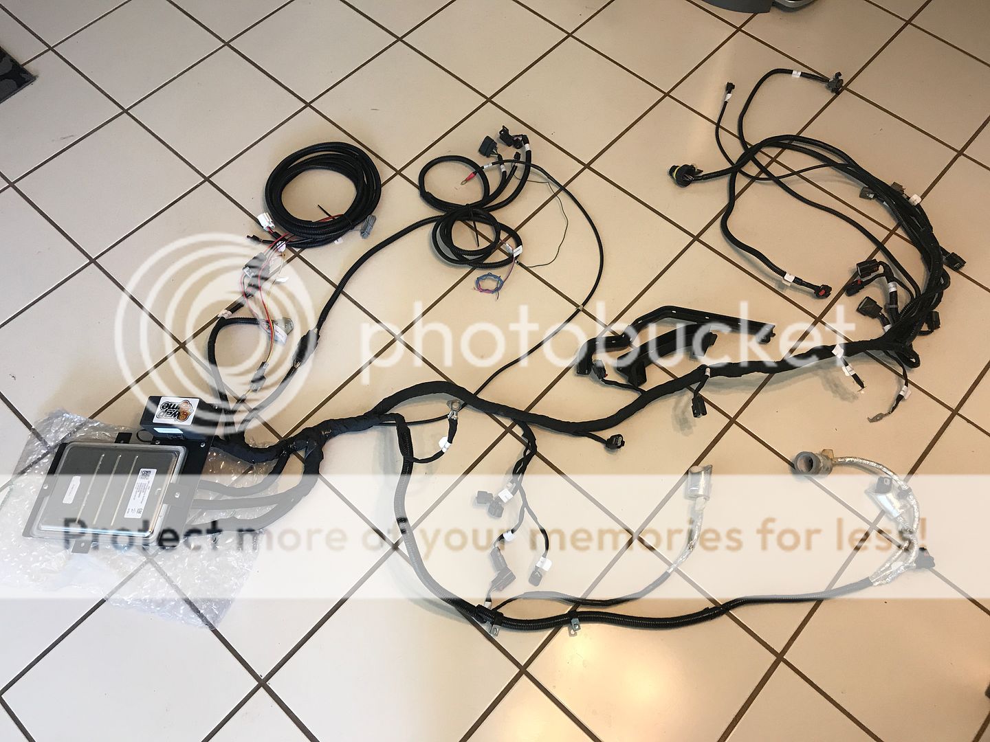
I received my engine harness back from SwapTime. It was well packaged and I think he did a very good job with it. I don't have "normal" layout for a Gen 5 and he worked with me on placing certain circuits in different places.
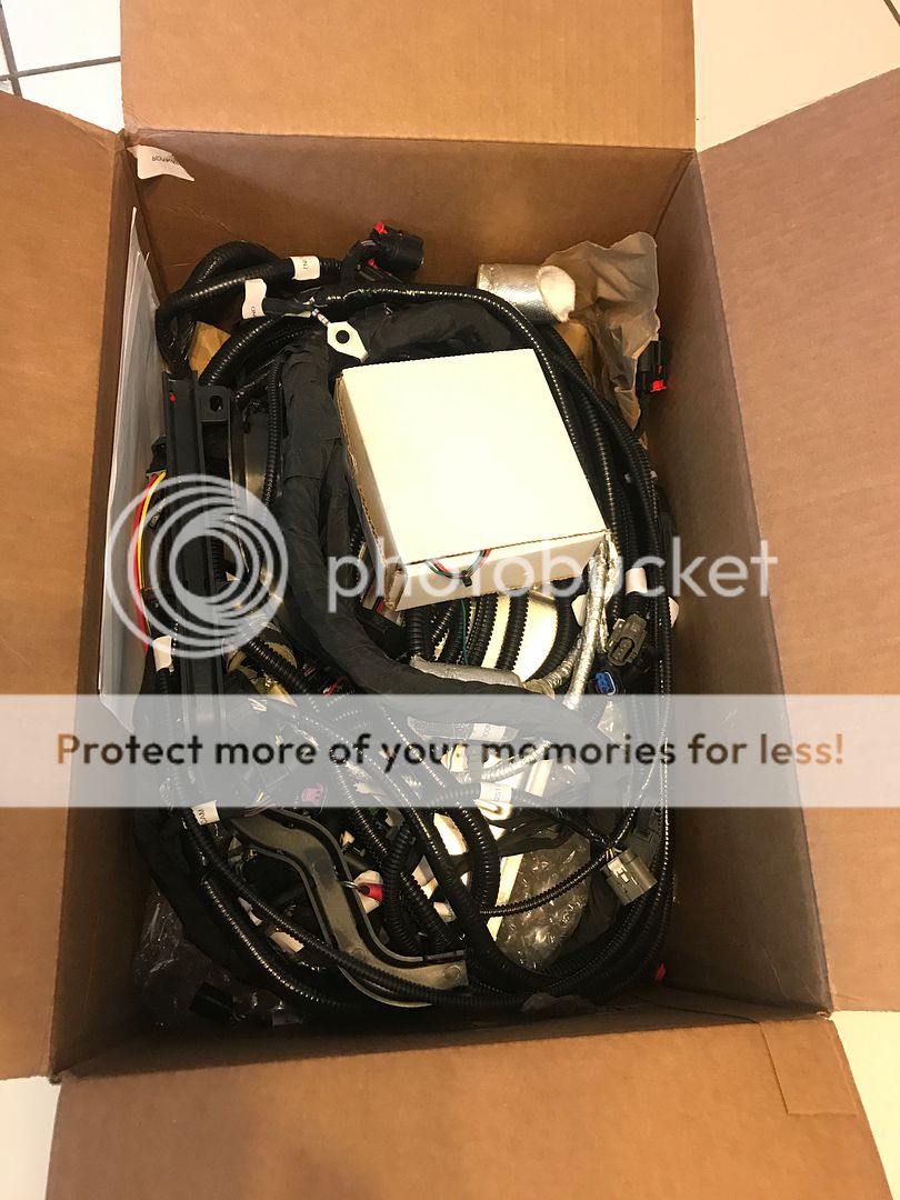
I opted for the BIM-01-2 OBD2 interface from Dakota Digital to run my gauges (also Dakota Digital). He hardwired it into the harness so I won't have to take up the OBD2 port using this module.
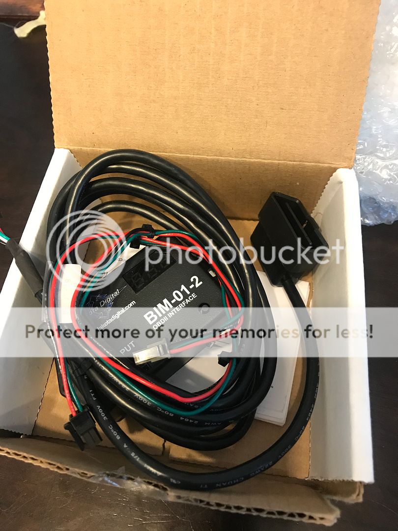
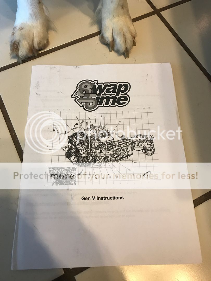
My dog, Ruger, helping me get everything out of the box. It came with some easy to follow instructions on how to wire everything up.
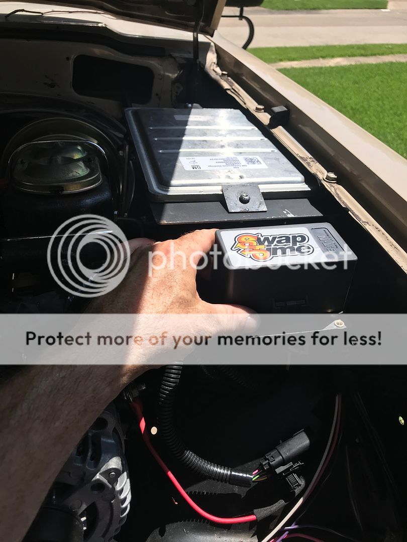
The harness comes prewired with a fuse box (right next to the computer). You basically wire it in like a relay. There's a turn on wire that hooks to the "key on" ignition and cranking, a ground, and a power wire that hooks directly to the alternator. I'm unclear if this particular circuit is fuse protected in the fuse box or has a fuse link where it attaches to the alternator. I'll call him about that. But if you are following this Mitchell, maybe you could clear that up.
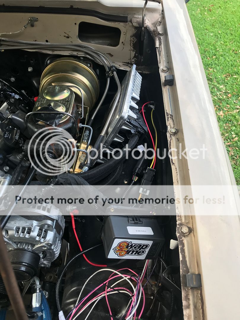
This is me trying to find room in my already cramped engine bay. I had to separate the fuse box from the computer in order to fit everything.
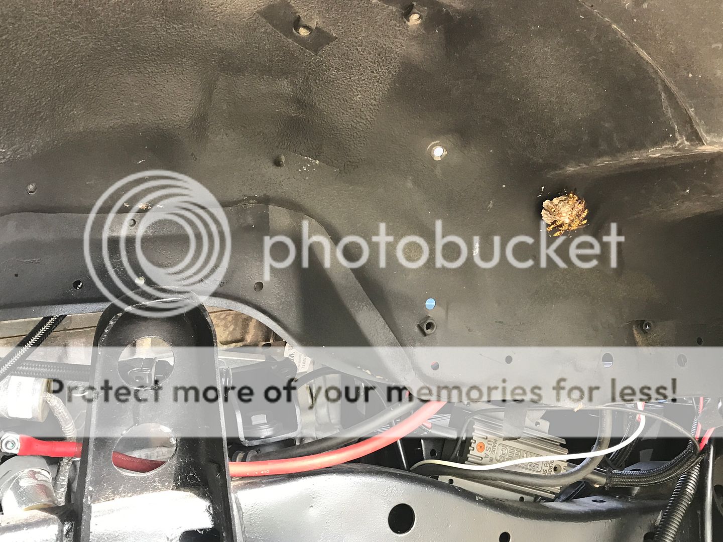
I had been working in and around the engine bay for about an hour before I noticed my guests inside the passenger wheel well. They didn't seem to mind me working in close proximity with them.

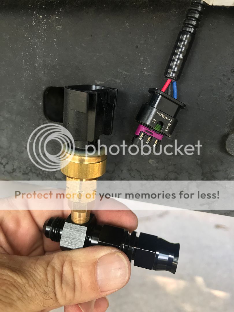
I didn't communicate to Mitchel that I'd be running a stock oem low pressure fuel sensor and he had it wired for a different kind of switch. One phone call away and I had a pigtail in the mail along with my new "strait" gas pedal. I wired it in easily enough.
just a random shot
The computer and fuse box ended up in these positions
I have a laundry list of things to finish before I can start it up.
rebuild the exhaust manifolds
build an exhaust all the way to a muffler (minimum)
fab a bracket for the power steering reservoir and run lines to it
tighten and secure the fuel lines
fill with transmission and engine oil
possibly prime the oil system
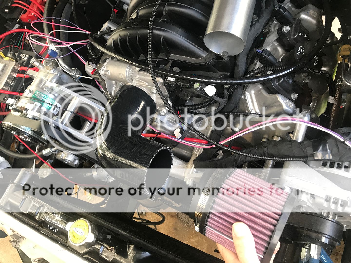
finish the intake tube with the MAF sensor
air intake mock up
exhaust y-pipe
The anticipation is building on how well all of this hardworking is going to pay off. Hopefully, it will start without any issues or something easy to fix. I'm going to purchase his Muscle Car Module next month. It should take care of a few other issues I've been worrying about. Namely: the reverse light and the neutral safety switch. I will also allow me to move into the manual mode to use the bump switch feature.
I received my engine harness back from SwapTime. It was well packaged and I think he did a very good job with it. I don't have "normal" layout for a Gen 5 and he worked with me on placing certain circuits in different places.


I opted for the BIM-01-2 OBD2 interface from Dakota Digital to run my gauges (also Dakota Digital). He hardwired it into the harness so I won't have to take up the OBD2 port using this module.

My dog, Ruger, helping me get everything out of the box. It came with some easy to follow instructions on how to wire everything up.

The harness comes prewired with a fuse box (right next to the computer). You basically wire it in like a relay. There's a turn on wire that hooks to the "key on" ignition and cranking, a ground, and a power wire that hooks directly to the alternator. I'm unclear if this particular circuit is fuse protected in the fuse box or has a fuse link where it attaches to the alternator. I'll call him about that. But if you are following this Mitchell, maybe you could clear that up.

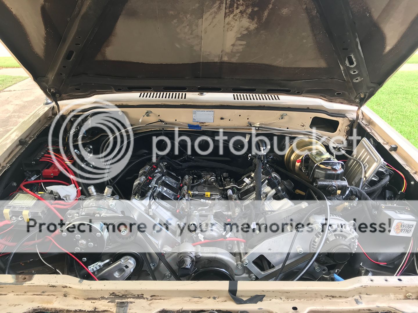
This is me trying to find room in my already cramped engine bay. I had to separate the fuse box from the computer in order to fit everything.

I had been working in and around the engine bay for about an hour before I noticed my guests inside the passenger wheel well. They didn't seem to mind me working in close proximity with them.


I didn't communicate to Mitchel that I'd be running a stock oem low pressure fuel sensor and he had it wired for a different kind of switch. One phone call away and I had a pigtail in the mail along with my new "strait" gas pedal. I wired it in easily enough.

just a random shot

The computer and fuse box ended up in these positions

I have a laundry list of things to finish before I can start it up.
rebuild the exhaust manifolds
build an exhaust all the way to a muffler (minimum)
fab a bracket for the power steering reservoir and run lines to it
tighten and secure the fuel lines
fill with transmission and engine oil
possibly prime the oil system
finish the intake tube with the MAF sensor
air intake mock up

exhaust y-pipe


The anticipation is building on how well all of this hardworking is going to pay off. Hopefully, it will start without any issues or something easy to fix. I'm going to purchase his Muscle Car Module next month. It should take care of a few other issues I've been worrying about. Namely: the reverse light and the neutral safety switch. I will also allow me to move into the manual mode to use the bump switch feature.


