When you click on links to various merchants on this site and make a purchase, this can result in this site earning a commission. Affiliate programs and affiliations include, but are not limited to, the eBay Partner Network.
Looking for 81, 82, 84, 85, and 89 Truck Engine Wire Diagram books. The ebay prices are crazy for these, hoping someone has some kicking around for a reasonable price. Just needs to be readable and complete, not worried about how pretty they are. Below is a pic of my 86 book. Also missing 88 (might have a source already). I use these books for the pigtails I'm planning to make, sub harnesses, etc. I also use them to figure out interchanges between the years and generally help people with wiring issues. It's just not cost effective to buy them at $100+ each, but I know people need parts/help for this era.
I don't have any EWD's for you, but any chance you'd be willing to help me out with some pages out of the '86? The body-engine connectors are a mystery...
🍻
There's a couple different places where the harness hooks into a body/dash harness. Which connector you need pinout info on?
These diagrams aren't great for pinout data, I'm actually slowly working on a website for pinouts because of it. Main target will be things like ECU connectors, sensors on the engines and such, but interconnect (harness to harness) connections would be good to add too. Anyway, a couple photos of the connector works best and there's like 6 variations of the wiring for 86, so have to ask which engine, auto or manual, 2wd or 4x4, and 49 state or california emissions (emissions sticker under the hood says FED for 49 states). California emissions trucks came stock with an O2 sensor, not sure if there was much else different.
Legend! A website with all the pinouts would be so helpful. Doing a 3.4 swap into a first gen 4runner now.
These are the connectors. I believe they are N1 and N2 behind the passenger kick panel and were originally connected to the 22RE harness. (Auto 4x4, Fed) Thank you!
Looks like your initial research lines up with the wire diagram I have. These interconnect style connectors are already interesting to try to figure out a good name for each pin since it effectively connects two things together across the connector. I tried to label everything in the context of your truck and special notes like manual only for pins that should be empty in your connector. I'm just running off the connector drawings you sent and the fact the one is yellow.
The wire diagram has a conflict, I've found a few of these in this book. I guess this era of book was made by people and less automated so more mistakes, or I'm not reading it 100% perfect. I included the wire colors for the conflicts so you can identify which wire it is, reporting back which you have would help the site once I get something put up online.
N1
1 - Auto oil temp sensor pin 4 to auto oil warning computer
2 - SP2 trans speed sensor
3 - S4 (trans shift solenoid 4)
4 - 4wd indicator in cluster
5 - Backup light switch to Connector H1 pin 5 for reverse lights
6 - AC clutch signal from AC Amp
7 - Neutral signal from neutral start switch
8 - 4wd indicator switch
9 - 2L signal (2nd gear) signal from neutral start switch
10 - S3 (trans shift solenoid 3)
11 - S2 (trans shift solenoid 2)
12 - S1 (trans shift solenoid 1)
13 - IDL signal (from TPS)
14 - Eng fuse to backup light switch (for reverse lights)
14 - +B to neutral start switch (red wire)
15 - Engine coolant temp signal for gauge
16 - Low oil pressure light in gauge
17 - AC Idle up VSV from AC Amp
18 - IDL to ECT Computer (trans)
18 - AC Idle up VSV from AC Amp (White/red on female side, Black/red on male side)
19 - Auto oil temp sensor pin 5 to auto oil warning computer
20 - Low (1st gear) signal from neutral start switch
N2 (Yellow)
1 - VCC ECU pin 12 Connector W to Pin 3 of Hac Sensor (White wire)
1 - ECU pin 17 connector W to Pin 4 connector F of gauge cluster (Green/Blue wire)
2 - Manual Only - ECU pin 17 connector W to Pin 4 connector F of gauge cluster
2 - Auto oil temp sensor ground (green/black)
3 - ECU NSW Connector X pin 1 to Cold start injector, Neutral start switch pin 2, and N2 pin 7
4 - ECU connector W pin 13 to O2 sensor pin 1
5 - ECU VF connector X pin 2 to Check connector P pin 4
6 - Circuit opening relay (pin 1, switched power/output) to Air Valve pin 2
7 - Manual only - Starter relay
8 - Manual only - E2 Ground to TPS pin 4 and Hac sensor pin 2
8 - Auto oil temp sensor signal (green/yellow)
9 - ECU Connector W pin 7 to Check Connector U pin 1 labeled as "T"
10 - +B from EFI relay to VSV for fuel pressure pin 1
11 - E1 ECU ground connector X pin 7 to Ground point D (Intake Manifold)
12 - From ignition switch (ST1 pin) to Neutral start switch, ultimately this wire gets +12v and kicks the starter on.
12 - NS signal to ecu (neutral start) - Brown/Red wire
13 - E2 Ground to TPS pin 4 and Hac sensor pin 2 (Brown/Black wire)
13 - Manual only - E1 ECU ground connector X pin 7 to Ground point D (Intake Manifold) (Brown wire)
14 - ECU pin 8 Connector W "W" signal (warning) to Check engine light in gauge cluster, connector G pin 4
Can't really guarantee those pinouts are right, but that should get you something to start with. The newer diagrams from around 1990 are much easier to read and follow, but they also don't have a simple pinout table. Ironically GM actually does make pinout tables.
I think ideally I'd get a list of wire colors for each connector and which pin they relate to on your truck would be great so I can validate which signal is actually used in the conflicted items. Having more books might help too, if there's a mistake, fair chances they are fixed in another year if nothing changed.
Amazing, thank you so much! I can get started on mating the harnesses now.
Of course, the diagrams and the harness never quite line up but it's close.
Here's a link to a spreadsheet with my colours on both M and FM sides of the plugs. Hope it helps with your pinouts.
(For the N2 connector, my EWD colours are going off an Alldata drawing, I don't trust them.)
Yea I have alldata too, their diagrams are from Toyota books, so the diagrams are good, but their system of finding the right page sucks. I know they are trying to hide the fact that their system is just book scans and they tried to make all manuals fit into the same format to match their system and it just doesn't work all that well. I wish they just made the manuals accessible as the books were designed with hotlinks to the sections basically like a well made PDF file. The Toyota TIS diagrams are laid out so much better than Alldata and much much higher quality (source docs instead of low quality scans). The amount of money Alldata gets for their system, you would think they would recreate the wire diagrams and such in a standardized format so their system actually would make sense and they could make it fit their system design better.
Wire diagrams are probably beyond my scope for my projects, but I think for vehicle wiring it would make sense to make an interactive wire diagram (modernize the concept of a wire diagram). Basically there's 2 ways to look a wire diagrams, one is the physical layout of the harness, wire colors, pinouts, etc, and the other is the actual circuit design layout. If the same source data could populate both views of the diagram and gave solid pinout data, connector views, maybe some specs if it's a testable component, etc. I was working on a system for atv wiring diagrams that followed that concept. The actual building the diagram/source data is the hardest part. If I can make it work for atv's though, then ideally I could make it for cars as long as I can understand the OEM diagrams well enough to port the data. Conflicting data is where it kind of breaks down though lol.
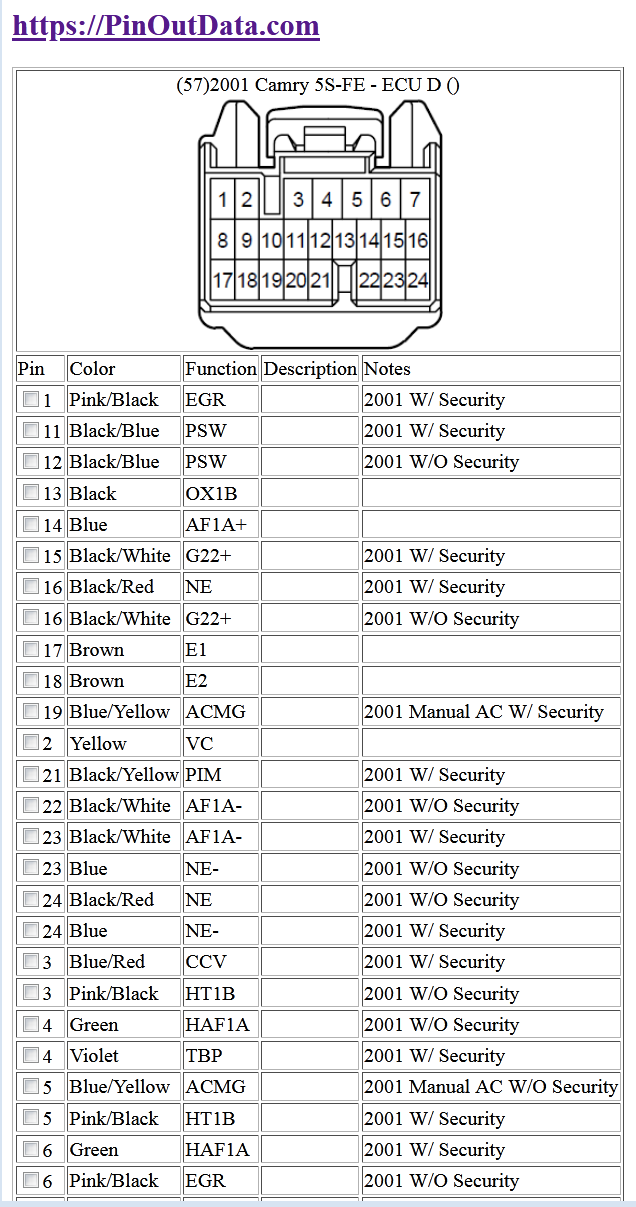
The whole concept of my pinout website idea came from people wanting to do engine swaps. I also know it's insanely useful to have pinouts of sensors and such too. Here's a small sample of my local version of the site. No fancy formatting really and this is the admin side of it so I added check boxes and such so as I cross ref to other years I can check to see if there's any changes, if not I can just add the fitment info to the existing pinout, if it's different then I get to add all the pins for the new fitment. Very manual process currently lol.
One thing to note is I need to break it down a bit farther so the pinout only gives one variation of the vehicle instead of all for the given year. Like in that table, 2001 camry with security, manual ac which would hide all the W/O security lines. Some of these options gets really confusing fast. Like 2002+ camry the date of production, country of origin (usa vs japan), 5 speed auto vs 6 speed auto all can effect the wiring/pinouts.
I haven't really thought too hard on how to monetize it to pay for hosting and my time assembling the data into pinout tables, my default idea is ads and make it free to access. Maybe make a compare system if I standardize the signal names somehow so it can show from and to connectors, which wire goes where, and which wires don't match up. It won't be a perfect system since I won't know if all of the signals are compatible, but it should be a solid starting ground I'd think. I also had an idea of allowing comments on those pages so people could post if the wiring worked out for them, and if they ran into any issues they could add notes for everyone else to reference. The compare system I'd think held behind a small paywall would be a reasonable way to monetize the site, but not sure if it would make enough with my standard of charging low prices. Like if I could charge everyone say $5/month for access to the whole site, it would probably make more than enough for me to make it a full time job, but that kind of goes against me wanting to make this data available for everyone.
To give a basic concept of what I've done in the past for the atv world, check out my atv website for tech specs and some tables like VIN lookup tables, OEM Carb ID, etc.
Anyway, what year/make/model/options was the 3.4L 5vz from? Once you get the wiring finalized I'd be interested in your notes to compare how my system does for this engine swap compare concept if/when I get the pinout system designed well enough to support that type of design.
I noticed you have some ?'s on the spreadsheet, I might be able to clear them up a bit.
Like SPD is a speed signal, generally speaking atleast for early wire based and cable based + efi speedometers get a VSS from the trans, and the gauge cluster converts the signal (or just passes it on) to the ECU. From my understanding it's mainly used for transmission shift points clearly for automatic.
I also build "simplified harnesses" for the derby guys, so if you need the bare min to make the engine atleast run, I can get you that data in a PM. I've already done it on a 97 4runner 5vz. It's just to make the engine run, no transmission or dash signals. Toyota's are setup generally so you physically shift into 1st gear and the trans is in 1st, same with reverse so for derby use no trans wiring is needed, and the simplified harness is more of a power adapter, it powers sensors that need 12v and the computer.
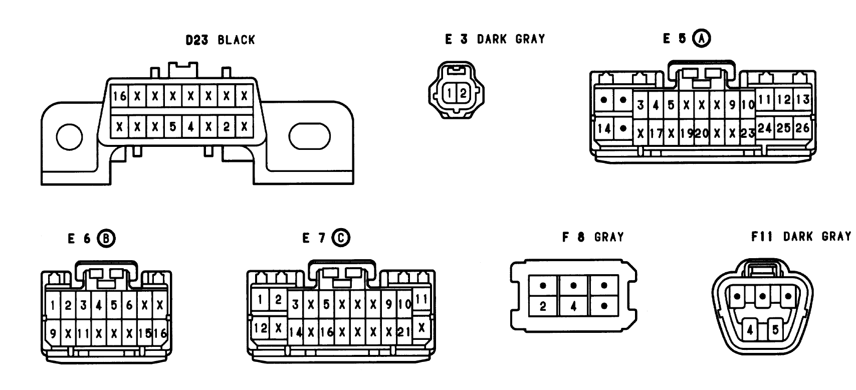
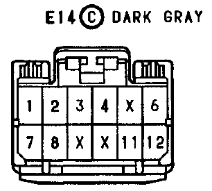
Your 22RE ECU connector image is Toyota's OLD connector drawings. Let me see if I can find a more modernized version in a newer manual. These are clearly the harness connector side. 22, 16, and 26 pin in this pic, I'm sure you can extract what you need from the image. Oh found the 12 pin too, manual camry's ran the connector in 94 =).
Anyway, I've done this pinout and pin swapping before on a 97 vs 98 T100 auto vs manual (auto ECU does work with manual harness with slight mods), both 5vz engines, that was my first experience with Toyota TIS. I think the best thing to start with is to take all of the connectors you have on the engine harness that aren't connected to anything and get the connector name in the wire diagrams and put all the wire colors from your harness on it so you know which pins aren't used. You've might have already done that but it looks like there's a bit missing. Don't depend on the wire diagrams when you have the physical wiring to compare since humans made those diagrams, it's always possible there's a mistake. I have found real mistakes in the Toyota books, but it's been really minor stuff, one was on a Camry ECU connector, pin 12 was labeled twice, one year off the wiring matched up and one was pin 12 while the other mislabeled pin was pin 2 lol.
I kind of like your concept of having male + female sides of the connector in the same spot, I might update my site to include both versions as well. It would fix one of the design issues where one side is one color, but the other side is a different color. Of course it doesn't fix the issue where one pin has 2 wires crimped together that are also 2 different colors.
Also to clear up one thing a tiny bit, the E1 and E2 grounds (and E22, E3, etc) are computer grounds, some are body grounded, some are signal grounds. When you're matching them up the E1 vs E2 you can kind of ignore, you'd want to match up if it's a signal ground or body grounded one. It probably doesn't make a huge difference, but the signal grounds being "floated" makes the signal cleaner to the computer, the 0v reference has less noise on it basically.
Another interesting item engine swappers might like to check out is the open source engine management system called Speeduino. The hardware is open source, the code is, and the tuning software is free. Laptop + usb cable + tunerstudio and you can make the computer run the engine, tune the engine, and see live data as the computer sees it. Some people put a tablet or an LCD screen in their dash and run their gauges directly from those signals and are able to tune their car with that screen as well. Costs aren't bad, roughly $300ish for everything needed, only side side is, you have to convert the harness to connect to the aftermarket computer which is cutting wires and crimping new connectors on, or building a harness adapter. I just got one of these to test out for a stand alone harness for the derby group, if it works out well, I'm thinking I'm going to make a database of what settings, wires etc are needed to make the engine run. The derby logic is less is more, so bare min sensors in their case. An engine can technically run on just TPS and have a timer for cold starts, but MAP/MAF + ECT + IAT helps make things more accurate. I think right now not a lot of people use these mainly because there's somewhat of a steep learning curve in setting up the computers. If that part was well documented for several engines, then the actual tuning part is the only hard part. It only takes one person to build a stock tune and release it publicly to have a nearly drop in ready to go computer option that's fully controllable and tune-able for a reasonable price. Not 100% sure if it's technically legal for on road use, so clearly standard disclaimers applies to check your local laws and such (mainly EPA and emissions related I suspect, if you're deleting the cat, EGR etc, you're probably at the same level of gray area anyway).
Also, probably should validate which country you're in. Based on the Colour usage I'm assuming Europe or Africa. I think Australia also uses that version, pretty much everywhere that speaks english that's not the USA xD. The wire diagrams generally are USA/Canada based from what I've seen, so there might be some slight differences in your local wiring vs the diagrams.
Anyway, clearly I have a lot of "big" ideas, but I have tons of projects always going, so I have to dedicate time to projects as I have time. Good news is I'm self employed, but that also means I have to dedicate time to the projects that make money now as a priority. The interactive wire diagram idea I've had for a long time, but there's a lot of work to build the system and make it work with all cases. That's why I dropped the bar lower with a pinout site (https://pinoutdata.com). If/when I launch the site and get the special cases worked out, that's kind of step 1 to making the database work for wire diagrams which is basically connecting the pins of the connectors together + spices, loop backs etc.
BTW, I also reproduce some wiring on those 86 trucks, pig tails etc. Clearly you're not using the stock AC parts but here's an example. I don't really focus on the main harnesses since the cost to make them would be so high and low demand at that price point (in my head atleast). The smaller simpler harnesses I don't mind making one offs of and such as long as I have the connectors and wire colors on hand. Everything kind of interconnects with what I'm doing lol.
Nice looking products. Do you 3D print the Molex? Link is to '85 overall and pinouts for the important stuff. Body electrical section was long but I'll take some pics of the pinouts on that another day/week if you want them https://drive.google.com/drive/folde...e-?usp=sharing
Also, take a look at Scribd, I've found a bunch of obscure engine and electronics manuals there in the past. More than 6k hits for "toyota wiring diagram"
Not sure what you're referring to for Molex, in the computer world that's a power connector lol. Either case I don't have a 3d printer atleast yet, connector housings I think require too high of precision to 3d print at the current tech, atleast for consumer grade stuff.
I downloaded the images, can you also send the front/rear of the book so I know 100% what the source is? I'm fearing it's the 1985 Truck and 4Runner Electrical wire diagram book, which means pinout data doesn't exist for 85 and older. 1986 the diagrams do give pinout data, makes sense why there's so many mistakes in the 86 book if that's the first year with the extra info and around 88/89 is when they went color and usability was increased greatly. In 2000 they changed the book design again where all connectors are in a single section which for digital copies makes the usability not as good, but easier to find a connector if you know what it looks like.
FYI, that 85 wire diagram should be the same thing as the 85 service manual which is an "overall" diagram.
Also, fun tip, for digitizing a book like that, check out the free app called vFlat, it's a little weird to get used to, but overall it does a great job if the camera on the phone is good quality and you can take stable images. Almost scanner quality but very quick, a similar tech/logic is used for mass digitizing books except there's machines to auto turn the pages (it actually flips through pages like 30 per min).
Ironically, I have a wire diagram book for I think it was 1983 that had the connector pinouts as part of the wire diagram with the connector drawings sprinkled throughout it.
If the pinout data doesn't exist for 85, then about the only way to populate this data base is either hope someone is willing to post pics of their connector and label which wire colors are in which pin which then can be matched up to the overall diagram, or I'd have to buy the harnesses and do that process myself. Big thing in either case is getting the exact features for the vehicle so things are as accurate as possible.
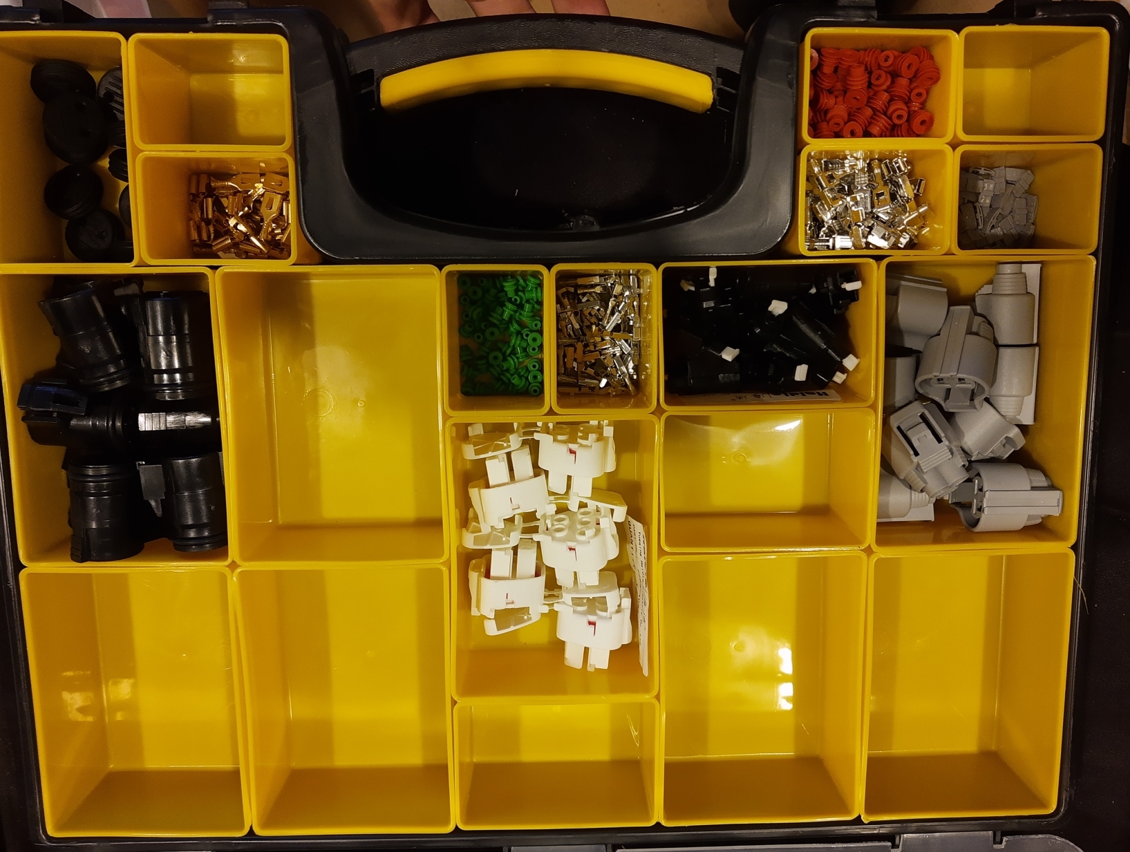
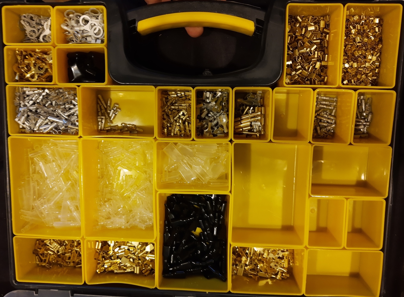
Back on the subject of connectors, I have a ton of organizers full of connectors, some more full than others. Probably have around 25 or so now. Way more connectors than what I currently have pig tails made for. Here's a couple just for an example. I buy from suppliers in bulk so I'm not paying $10+ per connector from Toyota. My main supplies were Honda atv based, but been getting more into Toyota connectors and also hitting some GM connectors too. I've spent probably $6000+ on connectors this year, mega expanding my coverage lol. I hope some day that my business is to the point I can buy years worth of connectors that are out of production (end of life) so I can make harnesses/pigtails etc with them to help keep things going. Reusing old connectors is always an option but it's a bit more work and lower quality end product.
Thought they look high def but it's been years since I've been around 3d printing so figured they'd made advances. Good that you can get them at a reasonable price. These diagrams are from the repair manual. The pinouts aren't on the overall but you can just look at the plug pinouts and transpose them. For example the water sensor has E2 and THW (water temp, terminal on ecu), look at the overall and you see the sensor has a wire tied into the AFM and another to the ecu. Thw is always (as far as I've know) a separate terminal on the ecu but we can confirm this on the ecu plug pinout if necessary also. So E2 has to be the AFM, and we can look at the AFM pinout and see that also has an E2 ground, so that plug is confirmed, THA is G-W, E2 is BR-B. On the AFM you have an additional ground on one side, then the ground we already know, a shared battery with the efi relay opposite the diagram (B), and the vs wiper in the middle (Y-L) vc next to it (L-R), and so on.
I'm talking pinout like the actual numbered pin of the connectors. Like the engine coolant temp example, yea it's 2 pins, which one in the connector is ground vs signal. I don't have the physical harness, so I don't have a way to confirm which order it is in the connectors. Also the actual connectors aren't shown. I've ran into this issue for an 84-85 pinout that changed in 86 for the AC sub harness under the hood that goes to the ac cluch and such.
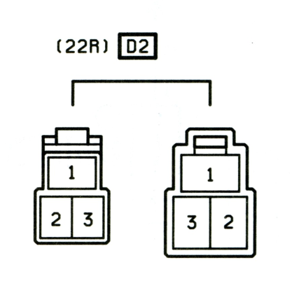
Here's the 86 version of the connector, 3 pin
1 - AC Clutch
2 - AC Idle up VSV (pin 1)
3 - AC Idle up VSV (pin 2)
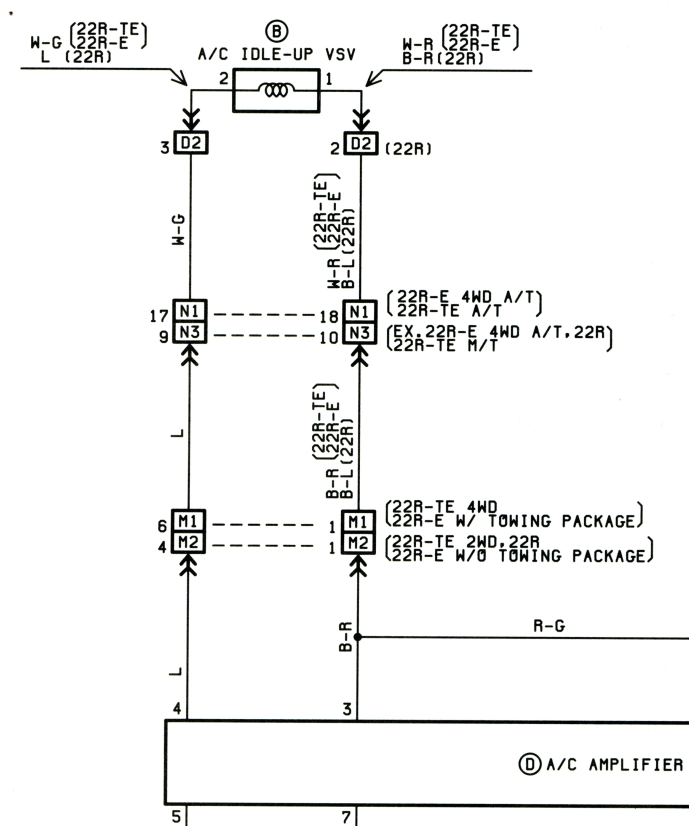
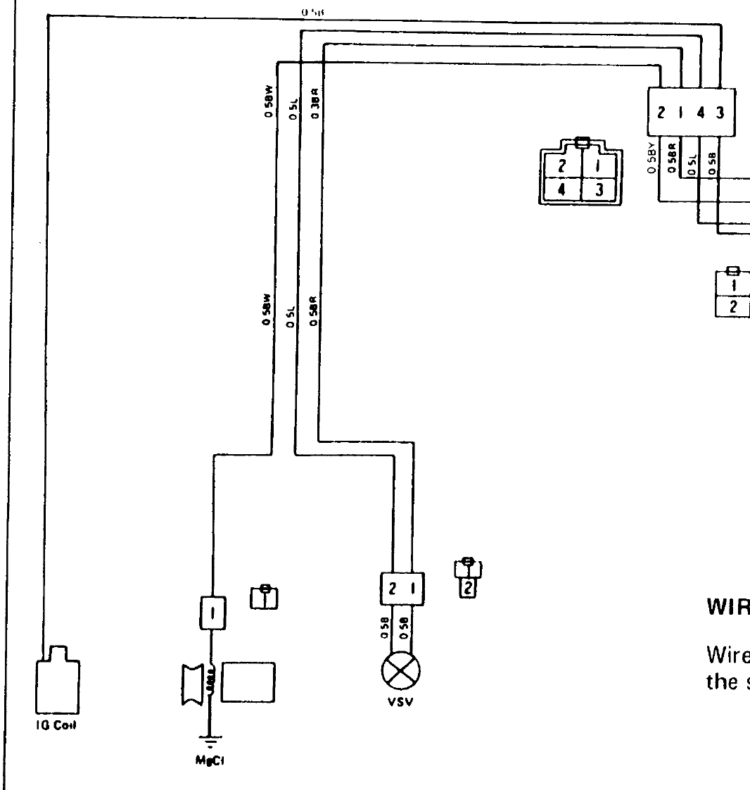
Here's a link to part of the diagram showing the pinout for this (pins 2 and 3, the connector above is D2 in the boxes, pin number is outside of the box).
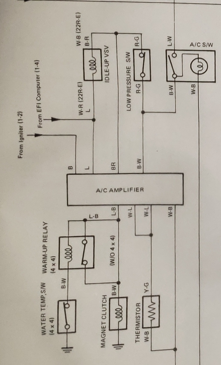
Here's the section from the wire diagrams you sent. As you see, it doesn't show there's even a connector between the AC amp and Idle up VSV.
Here's a different data source for 1984 (same as 85 from what I could find for pics on used harnesses on ebay and this is actually the target vehicle for a customer).
That diagram is great, it gives pinouts and is similar to the 83 book I have. So I get the pinout functions as follows:
The problem is... the Thermo switch also has a connector but it's not shown in the diagram. Finding a photo of that connector, or even the sub harness has been next to impossible. From what I can see it's a round connector 1 or 2 pin, I have that connector on hand, but can't validate the details on it until I can find a photo of the sub harness, or someone sends me a pic (I've asked in several locations, no luck so far). The 86 diagram shows the connectors for all points of the sub harness, and I happened to have an 86 parts truck with the harness, so that was simple enough to figure out.
The other special case that's not clear, the thermo switch is 4wd only, but what does the 2wd version look like, is it just the 4 pin connector with only 3 wires? I've found harnesses that claimed it's from a 2wd with the 4 pin connector, but never found a pic of the actual sub harness.
Anyway, I'm not sure where you're getting E2 from for the air flow meter unless you're referring to mtnthings's spreadsheet. If that's the case, that's from an 86 and wire colors are possible to change year to year, same with physical connector, so it's an unreliable method even though it can generally work. I'm kind of picky about what I publish, if it's half right, then it's also half wrong, and being wrong gives a site/person a lot of bad rep and discredits what they are correct about. That's one of the reasons I mainly use OE wire diagrams for most of what I do, everything else is just a copy of the original in their own style with compounded mistakes (OE mistakes + the people recreating the diagrams can make mistakes too). That's the whole concept behind me making a site on this stuff, since it's built in a database, interactive, and generated on the fly, if there's a mistake it can be fixed somewhat easily. It's a little hard to fix a printed book, and most online diagrams for newer stuff are pdf based which in theory should be easy to fix but I don't know their work flow for how they build them either.
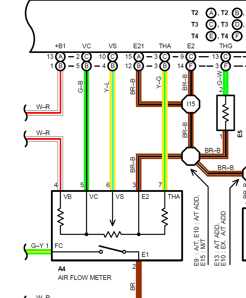
Check out the newer diagrams, they are a dream to work with compared to the older books lol. This is for a 1990 Pickup 22RE Air flow meter.
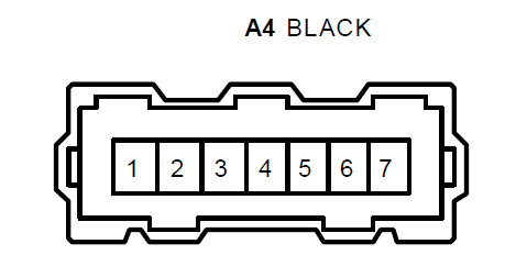
In color, all pins marked and all signal names (ECU and AFM side). The connector is "A4" which I'll post a pic of too, it's at the end of the section.
1 - FC (fuel control)
2 - E1 (body ground)
3 - E2 (ECU ground)
4 - VB (+B, aka +12v from EFI relay)
5 - VC (Should be +5V)
6 - VS (air flow signal)
7 - THA (air intake temp)
I really liked this era of wire diagrams, they also show the electric design internally, like the fuel control is just a simple switch to ground that is normally open.
Here's that A4 connector
I find it kind of crazy that I do have access to all of these wire diagrams, but even combined I don't have a for sure pin out for the 84-85 trucks on that AC sub harness. I really hope the 84 or 85 electrical wire diagram book has the pinout data if that's not what you already posted.
Hopefully some day I'll have a super amazing interactive wire diagram system made so all of this data can eventually be stored in a single point and ideally be easy to search to find the data. It will be a ton of work, but I think the end product might be somewhat revolutionary if I can build it and build it well. Clearly it's only going to be as good as the data source so for most things it will be 1990+ but I'd like to work out the pickups and 4runners for older than that. I have 79, 83, 86, 87, and 89 4runner books already, probably around $300 invested in them just in the hopes of covering those years accurately. I'm always open to ideas and new data sources I might not have thought of before. Like the physical harnesses I could try to buy and work them out in the wire diagrams you sent. Might not be the fastest route, but can't get much more accurate than the real harness lol.
I see what you mean about the junction connector pinouts not being shown. The junctions are represented by the dots at wire intersections, but nothing on the connectors. The pinouts are less critical there than the components themselves, of course, as long as the male and female connect correctly. For example any pair of mating 3 plug connector that are mirror-image pinned could join the vsv and amp, but the connector on the amp itself has to be the correct shape, and pinout. But then the end user is limited to buying a pair of connectors instead of just a single connector which isn't ideal. Agree about the 90s wiring diagrams being the best. Things got pretty obtuse after CanBus. I do have diagrams through the 5th gen but nothing before 1990 except this FSM and the '88 which you have already.
I didn't look at the spreadsheet until just now but I see all the AFM plugs he mentioned are the same as what I came up with so looks like that didn't change between '85 and '86. I got the colors/pinouts from looking at the diagrams I uploaded already from my phone in bed last night through process of elimination. Not as easy as the later diagrams but not too bad, and the AFM would be one of the tougher ones since there are multiple connections between the ECU and AFM. So back to that coolant temp, E2 is ground and the wire colors are like so
I only looked at like the first 10 pics, I didn't realize those other connectors existed. Is that in the same book? I was thinking it might have been a book similar to my 83 book which covers all toyota models in 1983, so the whole thing is fold out pages. My 86 book only has fold out pages for the overall diagrams, the other ones are just standard full page.
I always wondered where those images with the connector + signal labeling came from, that's something that should be part of the wire diagrams as a nice quick reference lookup that doesn't exist even in the newer books. I see the AFM pin order is the same in the connector, but the drawing I'm not sure if it matches or not. If you visualize the bumps out as just counts, the counts match up to the shape.
Kind of crazy they don't give the linking info, great that signal is labeled on the connectors, but it lacks wire color, wire diagrams have color but lacks pin number or signal name. I dug through the low quality scan I have of an 85 factory service manual and looks like those pinouts came in the troubleshooting section. I'll have to keep that in mind if I ever open a repair manual up for a Toyota lol. I normally get 90% of needed info from the wire diagrams for electrical related issues.
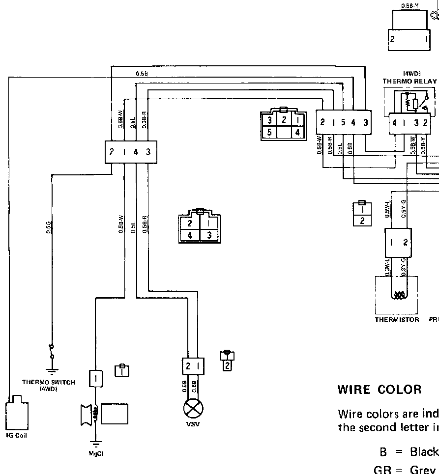
Back to my dilemma with the AC sub harness. Here's the 85 troubleshooting wire diagram... same connector different pinouts!
Either the pinout source is wrong, or those are one year only pinouts which makes things even more complicated to reproduce the parts lol. I'm pretty sure the wiring in 1983 will be different, but I didn't look up that year.
I just uploaded the ac system circuit for towing package, which is also different in '85 and does have that thermo switch, so even within the same year the plug is different. Looking at '88 it looks like that circuit also changes between EFI and carb models, although in '85 that particular connector didn't change. I don't have any junction pinout data for '88 either. So part of the difference you see might just be towing vs standard. '84 seems to lack rpm-AC feedback also. See this thread for an alternative method of controlling the RPM interaction - https://forum.ih8mud.com/threads/the...thread.855106/
Mistakes and just variances from the diagrams were pretty common in the early years. I know I ran into several things that didn't match up with the diagrams when I did the 3.4 swap harness for my '90 > '97, so even with the best diagrams there may never be a universal plug and play solution. Anyone trying to do wiring work on the early years has to be able to read a diagram and be prepared to adapt what they're doing due to the factory conditions, so it would be more than reasonable to have a disclaimer for anything you sell to that effect, IMO. From what I recall the '97 diagrams were right on but it was a couple years ago so I might be mistaken on that.
On the camry/corolla side of things, everything I've looked at has been spot on for 92-2001 with only one year mis labeling pin 2 as pin 12, there's a real pin 12 so real easy to detect the mistake in that case.
There's several sub harnesses involved with the AC systems and 2wd vs 4wd seems to effect some years as well. For 86, it was carb, efi and tow package for the interior sub harness difference and AC amp. Under the hood, the sub harness is only used on the 22r variation from what I remember. I don't know if the other ones include the AC wiring as part of the main harness, or what the physical difference is, but the wiring is the same, besides the interconnect change in that area of the harness.
The method I'd normally take for making a pinout site would be to start at the oldest year and work my way to newer vehicles, but it seems like the logic would work better to start with newer vehicles and work backwards since the newer stuff is easier to figure out and quicker to get something published.
 08-23-2021, 07:03 AM