Duffdog's front bumper build. lots of pics!!!
 09-23-2010, 11:07 PM
#1
Registered User
Thread Starter

Duffdog's front bumper build. lots of pics!!!
So, I have an 87 4runner. I already smashed up my rear smittybuilt bumper and got a custom tube bumper in its place. But now I wanted a front bumper. Unfortunately, I haven't seen any bumpers that I liked to look at. I actually liked the design of the front bumper, only wished it was stronger and I could mount a winch behind it. Nobody makes anything like this, so I decided to make it myself.
But first I had to strengthen the frame and add support from the A-arm lift bracket to the bottom of the frame rail.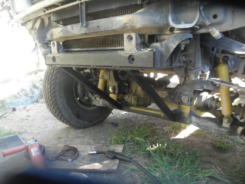
Heres the stock bumper with everything stripped off
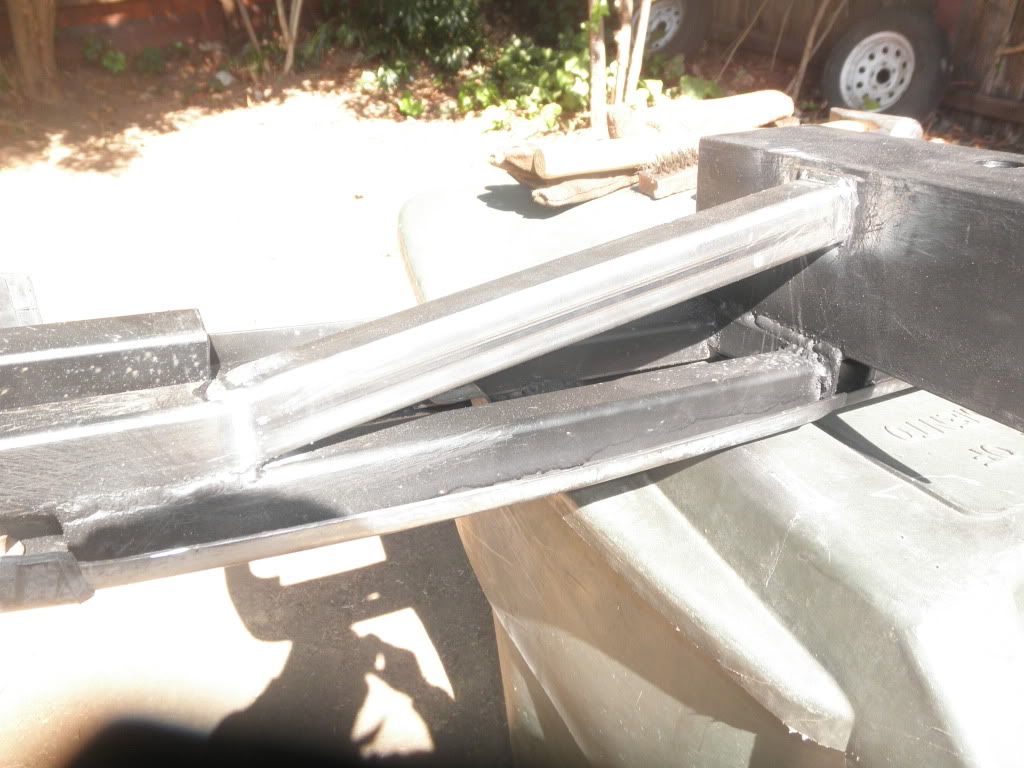
and here is the first bracing pieces that I welded to the bumper

I used 2 pieces of 4x4 angle 10" long for the new mounts and test fit them on the truck. I had to get longer metric bolts since there was so much more steel in the way.
Then, I continued bracing everything until I was satisfied that I could put the bumper cover pieces on and still have a strong bumper underneath.


At some point I welded the angle to the bumper and test fit the whole thing on the truck. It fit nicely.

Finishing touches included some more bracing on the outer corners of the bumper and some triangulated steel to resist bending.

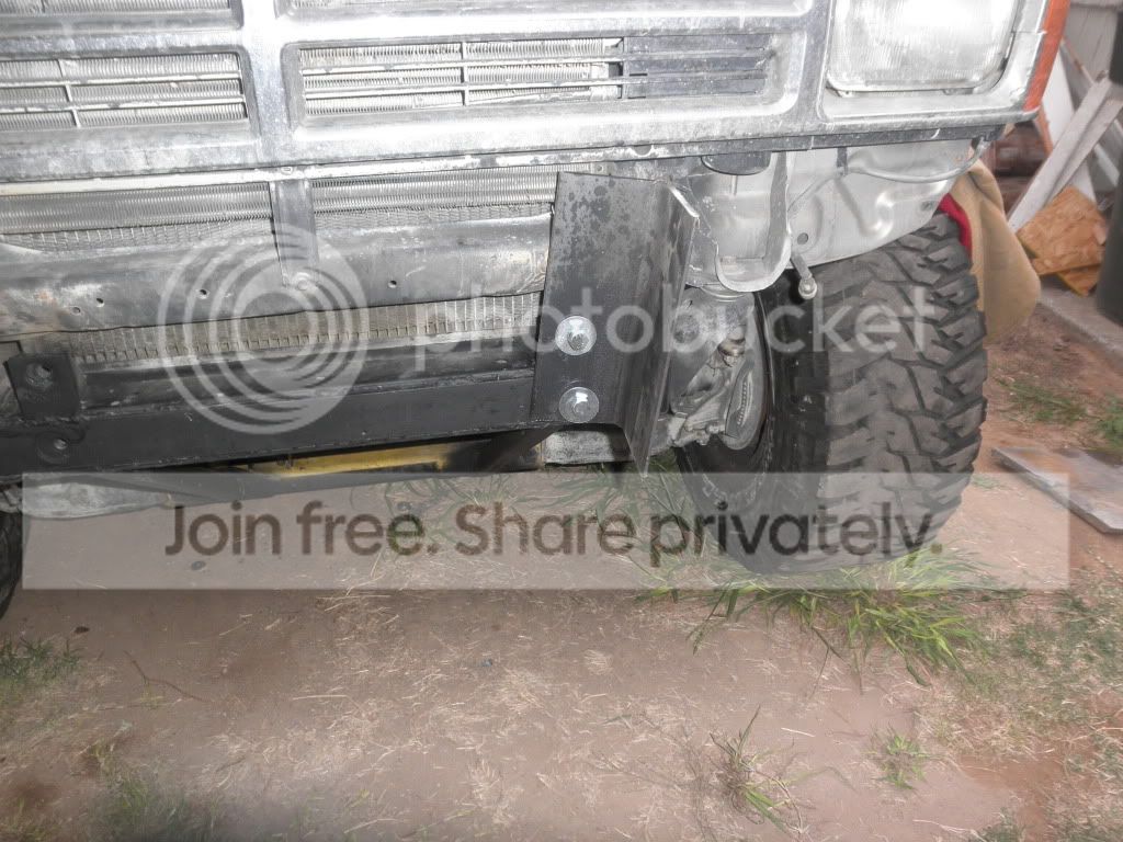
finished product. The bumper has enough room for a winch in below it and doesn't look ugly or weigh 500lbs. It just took me a couple of days to build this. Nevermind that it was literally my 3rd day welding...


But first I had to strengthen the frame and add support from the A-arm lift bracket to the bottom of the frame rail.
Heres the stock bumper with everything stripped off
and here is the first bracing pieces that I welded to the bumper
I used 2 pieces of 4x4 angle 10" long for the new mounts and test fit them on the truck. I had to get longer metric bolts since there was so much more steel in the way.
Then, I continued bracing everything until I was satisfied that I could put the bumper cover pieces on and still have a strong bumper underneath.
At some point I welded the angle to the bumper and test fit the whole thing on the truck. It fit nicely.
Finishing touches included some more bracing on the outer corners of the bumper and some triangulated steel to resist bending.
finished product. The bumper has enough room for a winch in below it and doesn't look ugly or weigh 500lbs. It just took me a couple of days to build this. Nevermind that it was literally my 3rd day welding...
Last edited by Duffdog; 09-23-2010 at 11:08 PM.
 09-24-2010, 10:46 AM
#2
Registered User
Join Date: Jun 2006
Location: Ocean Springs, MS
Posts: 262
Likes: 0
Received 0 Likes
on
0 Posts
I did something similar to a plate bumper I had. It was made from 1/8 C-channel and I added angle all over the inside to beef it up. Its fun learning to weld isn't it?

 09-24-2010, 01:19 PM
#5
Registered User
Thread Starter
It is fun learning how to weld. I messed up a lot, so I had to just grind the bad welds off and do it again until it looked right. I am used to inspecting welds, just never actually doing any welding. It was interesting to look at some of the weld errors that I made and know what I did wrong and why it would not pass inspection.
If anyone has any comments about my design, feel free. Its my first bumper build.
If anyone has any comments about my design, feel free. Its my first bumper build.
Trending Topics
09-24-2010, 03:11 PM
#8
Registered User

Join Date: Jul 2007
Location: Windsor, CO
Posts: 45
Likes: 0
Received 0 Likes
on
0 Posts
Does this really serve any purpose aside from adding weight? Where and how would you mount a winch to it? Reinforcing the x-member is a must so I like that part.
09-24-2010, 03:35 PM
#9
Registered User
iTrader: (1)
Join Date: Aug 2006
Location: Ft Collins, CO
Posts: 3,477
Likes: 0
Received 0 Likes
on
0 Posts
A few of things I noticed. I know you are new to fabbing, so hopefully it will help you out.
1. The nuts that are welded on the back side of the front crossmember that try to pull through the crossmember are around 7/8" in diameter. Your reinforcement plate holes look to be at least 1.5", so I am not sure adding that steel to it did anything more than beef up the crossmember itself. The nuts can and will still pull the frame. In fact, you may have just made it easier for them to pull through.
2. While on paper, adding the bracing from the crossmember to the IFS crossmember may seem like you are adding strength, you are actually creating a way to bend your IFS mount. If you hit someone with the bumper its going to try to twist the IFS now. Not to mention that dropping the front 3rd member is going to be a massive PITA as well. When we drop a 3rd to regear its, we usually drop that crossmember with it to allow easier access to it. You just welded it to the frame.
3. The angle iron mounting point will bend if winched with. You need to gusset it to help box it in top, bottom and middle. Otherwise it will just bend outward when you pull with it.
09-24-2010, 04:27 PM
#10
Registered User
Thread Starter
You would easily mount a winch in the center section between the two mounting points by welding a plate on the bottom of the angle iron.
09-24-2010, 04:31 PM
#11
Registered User
Thread Starter
A few of things I noticed. I know you are new to fabbing, so hopefully it will help you out.
1. The nuts that are welded on the back side of the front crossmember that try to pull through the crossmember are around 7/8" in diameter. Your reinforcement plate holes look to be at least 1.5", so I am not sure adding that steel to it did anything more than beef up the crossmember itself. The nuts can and will still pull the frame. In fact, you may have just made it easier for them to pull through.
I welded on the inside of the holes as well, I was thinking that this might prevent the nuts from moving at all.
2. While on paper, adding the bracing from the crossmember to the IFS crossmember may seem like you are adding strength, you are actually creating a way to bend your IFS mount. If you hit someone with the bumper its going to try to twist the IFS now. Not to mention that dropping the front 3rd member is going to be a massive PITA as well. When we drop a 3rd to regear its, we usually drop that crossmember with it to allow easier access to it. You just welded it to the frame.
True. I was thinking about how to remove the diff, but then remembered that when I put the lift in, I left the front xmember installed the whole time and simply dropped the diff into the bracket. But, I could see how most mechanics would want to remove the front xmember.
3. The angle iron mounting point will bend if winched with. You need to gusset it to help box it in top, bottom and middle. Otherwise it will just bend outward when you pull with it.
Theres a piece of .250 x 2 " flat bar on the bottom of the frame that I used to mount the xmember braces, but I will definitely make sure there is more gussetting.
more to come
09-25-2010, 05:58 AM
#12
Registered User
iTrader: (1)
Join Date: Aug 2006
Location: Ft Collins, CO
Posts: 3,477
Likes: 0
Received 0 Likes
on
0 Posts
The .250 flat bar has nothing to do with the angle iron trying to flatten out when winching though.
And, I don't see how you will fit a winch in there. The mounts are way too narrow, and you don't have enough room between the front of the bumper and the back where it mounts. Plus its not tall enough.
Most winches measure around 23"x7"x7". So, the winch tray would have to be on top of the mounting bolts, which is pretty much where the middle of the bumper is.
Plain and simple, is that its not going to fly as a winch bumper. But, as just a bumper its fine. Just don't ever plan to winch with it because its just not going to work.
Oh, and please don't take this as me attacking you or your bumper. Its just constructive criticism for the future as you learn how to fabricate.
09-26-2010, 03:42 PM
#14
Registered User
Thread Starter
ScottyC, I'm not upset at your comments at all. this was my first try at welding anything useful (besides a new shift lever in my GF's truck). I went wheeling yesterday and discovered that the bumper and the braces are not going to bend anytime soon. But I also discovered that I need some sort of under-truck armor since I bent the flimsy factory transfercase guard and trans support and had this wierd scraping sound from the double cardan joint grinding on the bent metal as it spun around. Next I will figure out how to make a strong removable skidplate for sliding over rocks.


Thread
Thread Starter
Forum
Replies
Last Post
WTB[WestCanada]: 1989 4runner stock front bumper and other items
lledwod
Items Wanted
1
08-30-2016 01:03 PM
GreatLakesGuy
The Classifieds GraveYard
8
09-04-2015 09:27 AM
Vargntucson
95.5-2004 Tacomas & 96-2002 4Runners
0
07-04-2015 12:15 PM


