
Wiring up some Autometer gauges this week...sanity check needed (Diagram inside)
 12-22-2010, 08:46 PM
#1
Registered User
Thread Starter
iTrader: (2)
Join Date: Dec 2009
Location: Pleasanton, CA - SF Bay Area
Posts: 2,159
Likes: 0
Received 7 Likes
on
5 Posts
Wiring up some Autometer gauges this week...sanity check needed (Diagram inside)
Hi guys....borrowing from another post of mine tonight and wanted to get more specific in the post Title/Topic...
I recently acquired a 3 gauge pillar and A/F and water temp Autometer Sport Comp gauge combo. Just ordered the oil pressure gauge to round out the set.
At the in laws and the new oil pressure gauge kit arrived - wahoo! Plan to run the wires and install the gauges tomorrow. I want to make sure I get the wiring correct. After reading the Automter installation guide online and that came with my oil gauge kit, this is what I think I'm going with:
Is this correct?
Also wondering, where in the cab I need to ground everything (lighting, gauges)?
And....any tips on hooking into the factory dimming switch?
Phil
 12-22-2010, 09:20 PM
#2
Registered User

Join Date: Oct 2010
Location: Chesapeake, Va
Posts: 36
Likes: 0
Received 0 Likes
on
0 Posts
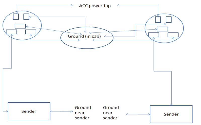
I am lost on your diagram. Are the circles at the top supposed to be relays? If so, I can't figure out why you need relays for gauges. The power draw shouldn't be enough to necessitate them.
If those are the gauges themselves: (I will use the A/F Ratio as an example) The red wire should go to the ACC power. (you can tie all three gauges together behind the pod so that you only have to tap into one wire) The white wire will be the wire that you want to tap into the dimming knob in order to get the lights to dim with the dash lights. (All of these can be tied together as well.) The violet wire goes to the sending unit and can not be tied in with the wires from any of the other gauges. The black wire will go to ground. The ground can be anywhere on the vehicle that you can make contact with metal. I normally look for a bolt that is already being used as a ground for something else. (all of the ground wires can be tied together as well.)
I think you are a little confused because there should only be 4 wires coming from the gauge. (ACC, illumination, ground, and signal)
Heck, maybe I am the one that is confused with your gauges but the above info is how I have hooked gauges in the past to get them to dim with the dash lights. Also note that if the gauge lights are significantly brighter than the dash lights you can try different ohm resistors to try and dim the gauges to meet the brightness of the dash lights.
12-22-2010, 09:40 PM
#3
Registered User
Thread Starter
iTrader: (2)
Join Date: Dec 2009
Location: Pleasanton, CA - SF Bay Area
Posts: 2,159
Likes: 0
Received 7 Likes
on
5 Posts
Thanks VA07 - guess I should have been more clear with my post 
The daigrams I made with PowerPoint show the back of the gauges, where the top two posts are the +/- of the lighted gauge (not relays), and the 3 contacts below are the sender/ground/ACC contacts. I took this from the Autometer instructions (below).
Further to my intial questions, where on the dimmer switch do I wire the white (or black?) wire to get the dimming effect in the bulbs?
And, how do I test the "anywhere on the body" ground I use for the gauges and illumination bulbs?
http://static.summitracing.com/globa...m-3375(2)1.pdf
http://autometer.com/productPDF/1079A.pdf
Last edited by Philbert; 12-22-2010 at 09:40 PM. Reason: wrong url link
12-23-2010, 06:49 AM
#4
Registered User
Join Date: Oct 2010
Location: Chesapeake, Va
Posts: 36
Likes: 0
Received 0 Likes
on
0 Posts
One way to test is to test the continuity between the battery neg(-) terminal and wherever you are planning to ground. But it really isn't as complicated as you are making it. Follow wires under the dash and in the kick panel until you see some that are bolted via ring terminals. Use that. If you can't find anything that way, you can put a ring terminal on the ground wire and use a self taping screw to secure it to the body. If you do it this way though, be sure to remove the paint under the ring terminal so that you get good contact.
12-23-2010, 07:03 AM
#5
Registered User
Philbert, your sanity check failed. Your officially nuts. 
No really, sub'd in case I wind up doing this. Not that I don't know how wiring works, but just in case I miss something.
BTW I love that adapter you are gonna be using.
No really, sub'd in case I wind up doing this. Not that I don't know how wiring works, but just in case I miss something.
BTW I love that adapter you are gonna be using.
12-23-2010, 07:47 AM
#6
Probably won't be able to tie the gauge lights into the factory dimmer. Why? Factory setup is floating ground w/ the dimmer rheostat between all the dash lights and ground. Gauge lights are typically hard wired to ground with a single power connection to light up the light. What I plan on doing with the gauge pillar in my '85 is to tie all the gauge lights to a small resistor (for a fixed dimming level) and hook that to a light-switched power source.
If the gauge lights have two wiring connections (power and ground), then you can wire that into the dash lights. But you need to hook up both connections to the proper dash light "power" and "ground" connections, as both are important.
If the gauge lights have two wiring connections (power and ground), then you can wire that into the dash lights. But you need to hook up both connections to the proper dash light "power" and "ground" connections, as both are important.
Last edited by 4Crawler; 12-23-2010 at 07:49 AM.
12-23-2010, 08:06 AM
#7
Registered User
Thread Starter
iTrader: (2)
Join Date: Dec 2009
Location: Pleasanton, CA - SF Bay Area
Posts: 2,159
Likes: 0
Received 7 Likes
on
5 Posts
Cat's out of the bag, I know...
I'm really looking forward to the Glowshift stuff coming in the mail - just want to get this wiring right today.
I'm getting conflicting feedback from VA07 and 4crawler on the lighting route I need to take. Until I resolve that I think I'll just look for the "hot" wire when the parking lights are on, and tap into that.
4crawler, for what it's worth, each gauge has 2 wires for the light - a white (+) and black (-).
I'm still wondering where I need to ground the gauges - just anything metal in the pillar itself?
Trending Topics
12-23-2010, 08:14 AM
#8
For the dash lights, you just need to grab wires from both sides of any dash light. If you have the back-lit cig. lighter, that is an easy one to access. All that dash lights have a common power feed and then all the lights are tied to a common "ground-like" connection and that in turn goes through the dimmer rheostat to actual ground. So you need both wires from any dash light to feed the gauge back light.
Main cab ground is often on the floor/kick panel area on the driver's side. Mine is down next to where the cruise control module is, sheet metal screw with a bunch of brown ground wires coming off it. Or the sheet metal in the pillar are will probably work, just sand away any paint so you get bare metal contact.
Main cab ground is often on the floor/kick panel area on the driver's side. Mine is down next to where the cruise control module is, sheet metal screw with a bunch of brown ground wires coming off it. Or the sheet metal in the pillar are will probably work, just sand away any paint so you get bare metal contact.
12-23-2010, 04:44 PM
#10
Registered User
Thread Starter
iTrader: (2)
Join Date: Dec 2009
Location: Pleasanton, CA - SF Bay Area
Posts: 2,159
Likes: 0
Received 7 Likes
on
5 Posts
Installed
Hey guys,
So I spent most of today creating wiring harnesses for the cab, running wire into loom, and tearing apart my dash. I finally got the pillar installed, with all the wires run. All I need to do is connect to power, lighting power, ground in the cab, and run the wires to the engine bay.
That said, still need some input from you guys please on where to connect inside the cab - see below.
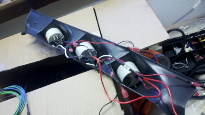
Here is the back, wired up:
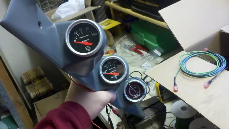
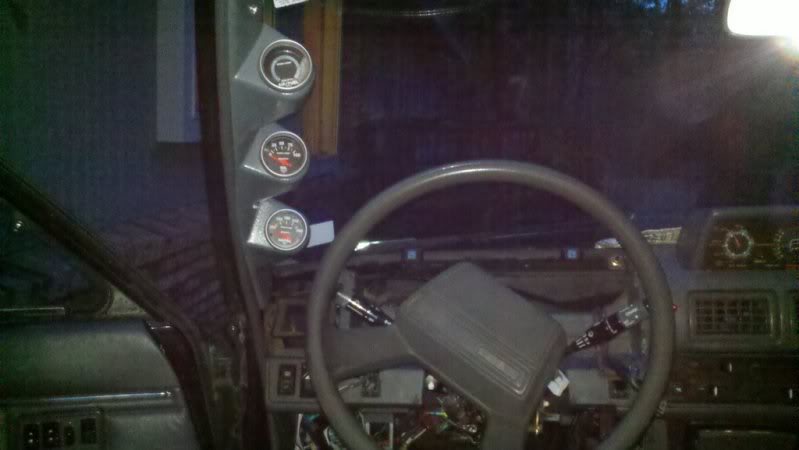
And the front mocked up:
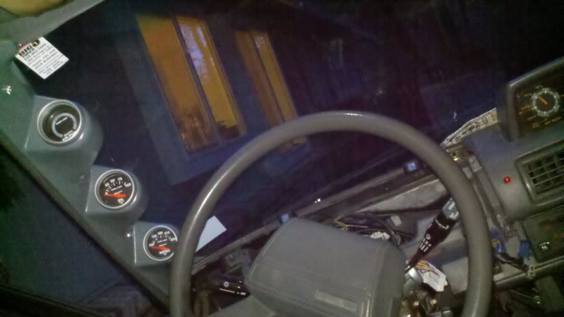
Installed!
Now, onto my questions about where to wire in the cab:
I have 3 wires to deal with: Ground, Power (ACC), and power for lights (triggered by parking lights - ideally hooked to dimmer switch).
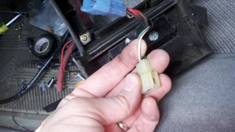
For the ground, I was thinking of hooking into the ground on the cruise control switch (black/white wire here). I used an ammeter to test resistance between it and the ground on the ignition - they shared the same ground:
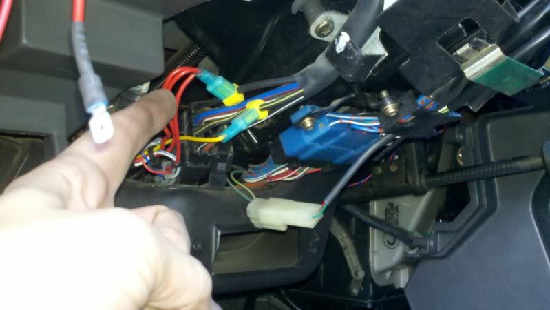
For the power wire, I was going to use one of these red wires, which is already tapped from my ignition system - I think it's part of my alarm system...
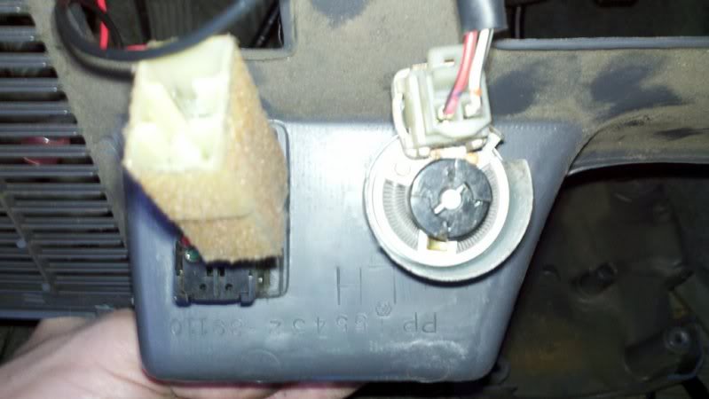
Now, for the lights on the gauges....really not sure here. I looked at the back of the dimmer switch and tried to test voltage with the parking lights on....kind of jumped all over. Anyone want to chime in here? I guess what I could do is tap into the wiring harness behind the gauge cluster, where the power for the dash lights come from....since it would already be dimmed at that point in the circuit?
Hope to wrap it up tomorrow. Won't get to hook up the senders till later.
On the AFM gauge, the online instructions say to hook up the 1 sensor wire to the OEM O2 sensor wire - it measures a range of 0 to 1 volt, and the LEDs on the gauge each light up for every 50 mA (20 LEDs). Does this mean I don't need a wideband O2 sensor to get a reading? It doesn't have a digital number readout - just "Lean/Stoich/Rich" using the LEDs - it's pretty simple looking.
What do you guys think about my approach to the wiring described above? Sane?
Phil
So I spent most of today creating wiring harnesses for the cab, running wire into loom, and tearing apart my dash. I finally got the pillar installed, with all the wires run. All I need to do is connect to power, lighting power, ground in the cab, and run the wires to the engine bay.
That said, still need some input from you guys please on where to connect inside the cab - see below.
Here is the back, wired up:
And the front mocked up:
Installed!
Now, onto my questions about where to wire in the cab:
I have 3 wires to deal with: Ground, Power (ACC), and power for lights (triggered by parking lights - ideally hooked to dimmer switch).
For the ground, I was thinking of hooking into the ground on the cruise control switch (black/white wire here). I used an ammeter to test resistance between it and the ground on the ignition - they shared the same ground:
For the power wire, I was going to use one of these red wires, which is already tapped from my ignition system - I think it's part of my alarm system...
Now, for the lights on the gauges....really not sure here. I looked at the back of the dimmer switch and tried to test voltage with the parking lights on....kind of jumped all over. Anyone want to chime in here? I guess what I could do is tap into the wiring harness behind the gauge cluster, where the power for the dash lights come from....since it would already be dimmed at that point in the circuit?
Hope to wrap it up tomorrow. Won't get to hook up the senders till later.
On the AFM gauge, the online instructions say to hook up the 1 sensor wire to the OEM O2 sensor wire - it measures a range of 0 to 1 volt, and the LEDs on the gauge each light up for every 50 mA (20 LEDs). Does this mean I don't need a wideband O2 sensor to get a reading? It doesn't have a digital number readout - just "Lean/Stoich/Rich" using the LEDs - it's pretty simple looking.
What do you guys think about my approach to the wiring described above? Sane?
Phil
12-23-2010, 05:18 PM
#11
Registered User
Join Date: Oct 2010
Location: Chesapeake, Va
Posts: 36
Likes: 0
Received 0 Likes
on
0 Posts
I apologize for the confusion. I didn't realize the dimmer switch used a floating/common ground. My advice was for systems who use the rheostat to control the voltage in and not the other way around. Take 4crawlers advice concerning the dimming of the gauges. I am sure I could figure something out by putting my hands on it, but doing it through the internet is a weakness of mine.
 Again, I apologize for the confusion.
Last edited by VA07; 12-23-2010 at 08:26 PM.
12-23-2010, 05:43 PM
#12
Registered User
Thread Starter
iTrader: (2)
Join Date: Dec 2009
Location: Pleasanton, CA - SF Bay Area
Posts: 2,159
Likes: 0
Received 7 Likes
on
5 Posts
No problem VA07! Thanks for the help
I'll use the dash wiring to tap from. I think I may try to find a more solid ground too.
Will update you guys when it's up and running. Not sure I'm excited about the AFM....sounds like it's just going to be constant flashing lights.....It was part of the bundle I got from Taro when I got the pillar.
12-23-2010, 10:02 PM
#13
Registered User
Just tap into the green wire (1992 toyota) that goes into your clock. It has 12v when lights are turned on.(its the one that tells the clock to dim) I know those gauges will be annoying at night but i think its your only option. I just installed a tach and thats what i tapped into. Just get a good multimeter and that will really help you.
I see your using some sort of scosche lock* stay away from those. Interior is ok but if there's any way it can get dirty it will get a bad connection and get warm. Leaving you with a mess. Trust me.
I see your using some sort of scosche lock* stay away from those. Interior is ok but if there's any way it can get dirty it will get a bad connection and get warm. Leaving you with a mess. Trust me.
12-23-2010, 10:18 PM
#14
Registered User
Thread Starter
iTrader: (2)
Join Date: Dec 2009
Location: Pleasanton, CA - SF Bay Area
Posts: 2,159
Likes: 0
Received 7 Likes
on
5 Posts
Just tap into the green wire (1992 toyota) that goes into your clock. It has 12v when lights are turned on.(its the one that tells the clock to dim) I know those gauges will be annoying at night but i think its your only option. I just installed a tach and thats what i tapped into. Just get a good multimeter and that will really help you.
I see your using some sort of scosche lock* stay away from those. Interior is ok but if there's any way it can get dirty it will get a bad connection and get warm. Leaving you with a mess. Trust me.
I see your using some sort of scosche lock* stay away from those. Interior is ok but if there's any way it can get dirty it will get a bad connection and get warm. Leaving you with a mess. Trust me.
I didn't quite understand the "schoche*" comment - are you referring to the washers on the gauges?
12-24-2010, 03:30 PM
#16
Registered User
Thread Starter
iTrader: (2)
Join Date: Dec 2009
Location: Pleasanton, CA - SF Bay Area
Posts: 2,159
Likes: 0
Received 7 Likes
on
5 Posts
Well, I finished today and buttoned everything back up, including my dash.
I ran sender wires to the engine bay for the oil and water senders, for when I install them.
I wired the A/F wire to the O2 sensor wire in the engine bay.
So, when I turn on my parking lights now, the autometer gauges light up, but my dash gauges do not :/
I tapped one of the wires to the dash lights earlier today but believe it should still be getting power.
Also, the A/F gauge doesnt' seem to work - it does the quick light show when I turn off the truck, but nothing when truck is running.
Any ideas where to start tomorrow with troubleshooting?
12-24-2010, 04:41 PM
#17
With the dash and gauge lights, you either want to use *only* the dash light wires (both the + and - wires) or none of them. Can't mix that dash wiring and the parking light wiring, for example. On my '85, I just use the parking light hot wire and ground for any back lights.
O2 sensor (assuming a 1-wire, unheated unit) will take a while to warm up, so you need to run the engine a few minutes before it'll register. When I wired up mine, I tested it and it was fine, then after buttoning everything up, it quick working. I recall that one of my sensor connections came loose when I was tucking all the wires in place. Traced that out and it has worked fine since then.
O2 sensor (assuming a 1-wire, unheated unit) will take a while to warm up, so you need to run the engine a few minutes before it'll register. When I wired up mine, I tested it and it was fine, then after buttoning everything up, it quick working. I recall that one of my sensor connections came loose when I was tucking all the wires in place. Traced that out and it has worked fine since then.
Last edited by 4Crawler; 12-24-2010 at 04:43 PM.
12-24-2010, 05:04 PM
#18
Registered User
Thread Starter
iTrader: (2)
Join Date: Dec 2009
Location: Pleasanton, CA - SF Bay Area
Posts: 2,159
Likes: 0
Received 7 Likes
on
5 Posts
Thanks 4crawler!
I'm still a little confused about the lighting wiring you mentioned above. What I did was, tapped into a hot wire from the dash lighting plug, but the ground that I used for BOTH the new gauge lighting AND the gauges themselves, was the cruise control switch in the photos above.
Are you saying that I can ground the new gauges' POWER to this same ground, but that for the new gauge lighting I need to run BOTH a hot wire and ground from the dash lighting harness, and not just the single hot wire I'm using now?
What happened to my dash lights do you think? Are they toast or do I just need to change the wiring to get it back to normal?
12-24-2010, 05:11 PM
#20
Thanks 4crawler!
I'm still a little confused about the lighting wiring you mentioned above. What I did was, tapped into a hot wire from the dash lighting plug, but the ground that I used for BOTH the new gauge lighting AND the gauges themselves, was the cruise control switch in the photos above.
Are you saying that I can ground the new gauges' POWER to this same ground, but that for the new gauge lighting I need to run BOTH a hot wire and ground from the dash lighting harness, and not just the single hot wire I'm using now?
What happened to my dash lights do you think? Are they toast or do I just need to change the wiring to get it back to normal?
I'm still a little confused about the lighting wiring you mentioned above. What I did was, tapped into a hot wire from the dash lighting plug, but the ground that I used for BOTH the new gauge lighting AND the gauges themselves, was the cruise control switch in the photos above.
Are you saying that I can ground the new gauges' POWER to this same ground, but that for the new gauge lighting I need to run BOTH a hot wire and ground from the dash lighting harness, and not just the single hot wire I'm using now?
What happened to my dash lights do you think? Are they toast or do I just need to change the wiring to get it back to normal?
So either use both sides of the dash light wiring or none of it, but do not use only one side or the other. It is basically all or nothing.
Problem with using one side, say the hot side and then a direct ground connection is that you are providing an alternate path to ground for the dash light current. It can either go through all the dash lights and the dimmer to ground, or it can go through your new gauge back lights to ground. Path of least resistance gets the most current.


