

Composite Winch Mount Bumper - Senior Design Project
 Feb 21, 2008 | 03:00 PM
#1
Thread Starter
Registered User
Joined: Jun 2005
Posts: 378
Likes: 0
From: Minnesota
Composite Winch Mount Bumper - Senior Design Project
As a senior composite materials engineering major, it is time to get to work on the senior design project: a fully composite winch mount bumper. Last semester my small design team performed strength and design analyses and worked out all of the theoretical stuff, now it is time to build!
A few different designs were reviewed, and the design we decided upon consists of a central support structure made of 32ply carbon fiber (autoclaved) that will be covered by a shell of 18ply glass fiber. This model was designed to be able to house and support an 8000lb winch. These two pictures show the basic design:
Front:
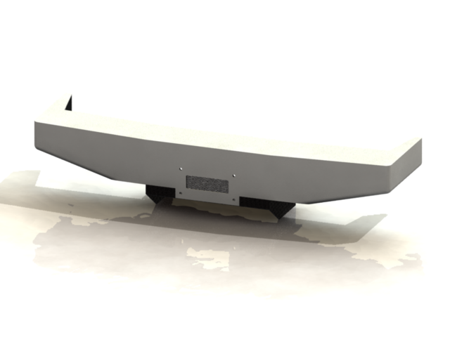
Back:
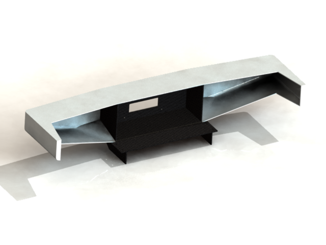
This particular design was created to bolt to the tow hook mounting points on the front of my 84 4Runner and is estimated to weigh about 40lbs assembled.
A few different designs were reviewed, and the design we decided upon consists of a central support structure made of 32ply carbon fiber (autoclaved) that will be covered by a shell of 18ply glass fiber. This model was designed to be able to house and support an 8000lb winch. These two pictures show the basic design:
Front:
Back:
This particular design was created to bolt to the tow hook mounting points on the front of my 84 4Runner and is estimated to weigh about 40lbs assembled.
Feb 21, 2008 | 03:07 PM
#2
Thread Starter
Registered User
Joined: Jun 2005
Posts: 378
Likes: 0
From: Minnesota
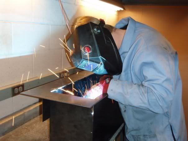
So far, we have begun to create the tooling that the center support structure will be laid up on. The tooling resembles a box that the carbon prepreg material will be cut and laid over. Once all of the plies are applied, it will get vacuum bagged and autoclaved. After curing, the composite part is removed from the steel tool.
The construction began by bending 12ga steel into a U-shape:
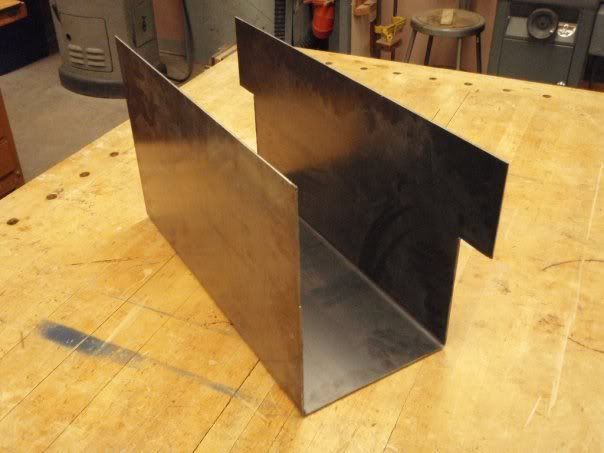
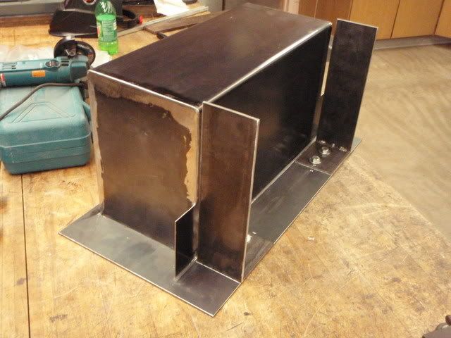
Next, 3/16" steel was cut to be used as a base. The bottom of the box is hollow so that the autoclave pressure does not crush the box.
Finally, the U-shape and two sides were welded to the base with a slight draft angle so that the cured part can be removed once it is cured. Because the metal will expand and contract with temperature differences more than the composite, the thermal expansion will also help to remove the part from the tooling.
That is how far we are as of today. After welding the sides in, JB weld was used to fill the seams. Tomorrow when it is dry I will grind and smooth the sides and radius the corners smooth. Not pictured are the two lower brackets that the lower supports will attach to. These two parts are removable to make laying up the fabric and removing the part easier. More to come as work progresses!
The construction began by bending 12ga steel into a U-shape:
Next, 3/16" steel was cut to be used as a base. The bottom of the box is hollow so that the autoclave pressure does not crush the box.
Finally, the U-shape and two sides were welded to the base with a slight draft angle so that the cured part can be removed once it is cured. Because the metal will expand and contract with temperature differences more than the composite, the thermal expansion will also help to remove the part from the tooling.
That is how far we are as of today. After welding the sides in, JB weld was used to fill the seams. Tomorrow when it is dry I will grind and smooth the sides and radius the corners smooth. Not pictured are the two lower brackets that the lower supports will attach to. These two parts are removable to make laying up the fabric and removing the part easier. More to come as work progresses!
Feb 21, 2008 | 03:20 PM
#4
Thread Starter
Registered User
Joined: Jun 2005
Posts: 378
Likes: 0
From: Minnesota
So far we have a little over a hundred $ in steel into it. Not sure on the cost of the composite materials, we are using department material that is donated to the university from businesses. One of the (potentially) major costs that we will be facing is that of a winch. So far we have contacted some of the major winch manufacturers to see if they would help sponsor our project, but we have not gotten any positive replies. Looks like I might be burning all of my tax return on a winch for this project if we cant get one donated or at a reduced cost.
Feb 21, 2008 | 03:25 PM
#5
Contributing Member
Joined: Jun 2005
Posts: 3,415
Likes: 10
From: Phx, AZ
That's a pretty cool senior project. Who gets to keep the finished product? Hopefully your instructor doesn't drive a Toyota. 
I am no engineer, and have almost zero knowledge of the materials you are using. But to me, a bumper is only as strong as it's mounting points.
How will you keep the bolt holes from elongating or worse tearing out?
How have you designed the bumper to withstand loads form different angles? Winching isn't always from dead straight 90 out the front.
Does this bumper design expect to handle impacts such as rocks, or is it mostly a study in strength with regards to pulling forces (such as winching).
These questions are by no means meant as knocks on your ideas or design, simply for my own benefit as I like to better understand such things.
Feb 21, 2008 | 03:35 PM
#6
Thread Starter
Registered User
Joined: Jun 2005
Posts: 378
Likes: 0
From: Minnesota
I'm glad to see some interest so far! If I didnt want some constructive criticism I wouldnt have posted up here; it is good to question such things.
The design was analyzed at both straight-on pulling and angled winching loads. The boxing of the main structural support gives pretty good strength, so the side loading should not be an issue. We also did some calculations and figure that the bumper *should* be able to sustain a 5mph impact with little to no damage.
With regards to the bolt holes, I am thinking of making a thin aluminum plate to cover the mounting tab to act like a big washer to prevent the bolts from tearing or pulling through. More than likely the finished product will stay with the department as I am not sure how many we will end up making (depends how it holds up to real-world testing!), but if an extra one happens to disappear...who knows!
Trending Topics
Feb 21, 2008 | 04:21 PM
#8
Thread Starter
Registered User
Joined: Jun 2005
Posts: 378
Likes: 0
From: Minnesota
I will have to go into some of the tech stuff a bit later, its on my desktop at home. We used mostly statics and mechanics techniques and a program called CompositePro to model the loading. FEA was not used (yet) because no one in my team had taken that class, but I am taking it right now so when we get to solid elements, I will examine things a bit further.
 Feb 23, 2008 | 10:01 AM
#12
Thread Starter
Registered User
Joined: Jun 2005
Posts: 378
Likes: 0
From: Minnesota
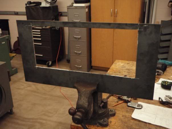
Made some progress on Friday afternoon. I ground down the seams that were sealed and rounded the edges of the box part of the tooling. I also fabricated two L-shaped brackets and drilled and tapped the base for them to bolt to. These brackets will be removable to allow the prepreg material to be formed to the box as well as to aid in removing the full part after curing. Soon I will fabricate a bracket to go between the tops of the brackets so that they do not flex during processing.
This picture shows the tooling as completed so far with a full-scale cardboard mockup of the center section. It fits perfectly.
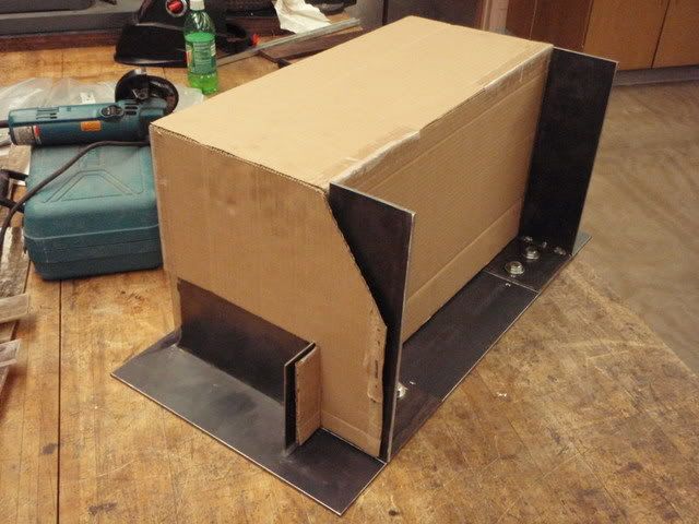
This weekend or early next week I will be sanding and polishing the tooling until it becomes as smooth as possible. At this point we can determine if a gelcoat or paint layer is needed to get it perfectly smooth so that the part will release.
More updates to come
This picture shows the tooling as completed so far with a full-scale cardboard mockup of the center section. It fits perfectly.
This weekend or early next week I will be sanding and polishing the tooling until it becomes as smooth as possible. At this point we can determine if a gelcoat or paint layer is needed to get it perfectly smooth so that the part will release.
More updates to come
Feb 23, 2008 | 05:45 PM
#13
Thread Starter
Registered User
Joined: Jun 2005
Posts: 378
Likes: 0
From: Minnesota
This evening I was thinking about potential problems that might be encountered when trying to remove the composite part from the tooling. One possible significant problem could be that due to the large part-tool contact surface area, the part may not want to come off easily. To fix this, I have come up with a way to allow compressed air to be used to 'pop' the part off of the tooling.
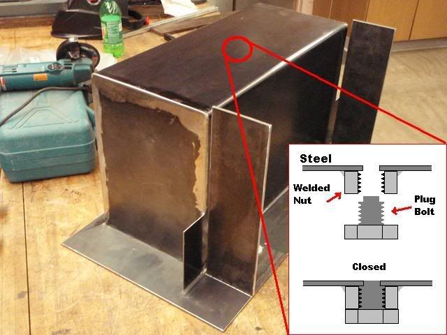
This picture shows where a hole (maybe 1/2" diameter or so?) could be drilled in the top of the box part of the tooling. On the inside, a nut will be welded of an inside diameter that is slightly bigger than the hole. This will allow a specially ground bolt to fit in the hole and plug it so that it is air tight and no resin leaks through. Once the part is cured, the bolt can be removed and an air fitting screwed in so that compressed air can be used to push the part away from the steel tooling.
My only concern is that the thin 12ga steel might warp when the nut is welded to it. I think that maybe just making a few tack welds and sealing the seam with JB weld should be sufficient to make the joint air tight with minimal warpage.
Even if the plug bolt is not perfectly flush with the surface of the mold, it could be positioned so that the fitting is on the part of the composite that will get cut out to allow room for the fairlead.
Feb 24, 2008 | 07:31 AM
#15
Thread Starter
Registered User
Joined: Jun 2005
Posts: 378
Likes: 0
From: Minnesota
Our welder is me most of the time, it will be alright. 
Today I am going to get an air fitting and a nut to fit it to see what things will look like when fit together. I figure it will be easier putting this fitting in now even if we end up not needing it because it will be somewhat more difficult to add it in once a cured part is stuck on the mold.
wjwerdna - I have been following your bumper build over in the Fab section and its looking awesome! I really like the integrated driving/fog light holes. I might have to modify our shell design to accommodate something like this
Feb 24, 2008 | 08:28 AM
#17
Thread Starter
Registered User
Joined: Jun 2005
Posts: 378
Likes: 0
From: Minnesota
Good question! It was one of our original ideas to be able to incorporate shackle mounts similar to an ARB type bumper to make this 'competitive' with steel bull bars in terms of features. I think that the first unit probably wont have shackle provisions, but if it is deemed strong enough, we can drill holes in the upright sections for them and make a (aluminum?) grommet so that it doesnt just tear through the composite under load.
I am hoping that shackle mounts will be feasible because I have used them on my current bumper a lot and they are an awesome feature to have.
I am hoping that shackle mounts will be feasible because I have used them on my current bumper a lot and they are an awesome feature to have.
Feb 26, 2008 | 09:35 AM
#18
Thread Starter
Registered User
Joined: Jun 2005
Posts: 378
Likes: 0
From: Minnesota
Good news! I received an email from Smittybilt today saying that they are willing to donate an XRC8 winch to the project! A BIG thanks to them for helping our team!
Today I made progress on machining the air plug. I will get some pictures of it up later today.
In other good news I was just accpted to University of Colorado Boulder for their MS/ME program in Aerospace Engineering, so all in all it is a pretty good day so far!
Today I made progress on machining the air plug. I will get some pictures of it up later today.
In other good news I was just accpted to University of Colorado Boulder for their MS/ME program in Aerospace Engineering, so all in all it is a pretty good day so far!
Feb 27, 2008 | 11:45 AM
#20
Contributing Member
Joined: Nov 2007
Posts: 776
Likes: 0
From: Indiana
I just graduated with my bs in ME. Anyway. The loads from the winching etc are not what concerns me but here are the things that do. First of all the mounting points to the truck, bolt holes etc will need to be a metal to bolt interface in my opinion. I think that adding metal plates over the carbon fiber in these locations would be a good Idea. Once carbon fiber frays (not sure how to exactly eplain what I am thinking but frays is the best description I could think of) It does not hold up nearly as well. The other thing that concernes me is impacts and scraping and sliding from rocks etc. This will likely chew up the bumper and begin to break up the smooth surface of the carbon fiber and threaten the integridy of the bumper. Metal does well with this but not sure about carbon fiber. Carbon fiber is strong but doesn't do too well with impacts. Plus you cant really repair it. You just have to replace it. Expensive too. Have you tried ANSYS for FEA. You can use ANSYS work bench which allows you to pull in 3d models from CAD. I have used Pro E mostly and workbench works well with that. I think it is a great idea none the less. I think it would be great for limited off road abuse but probably not a good Idea for the serious offroader who smashes his bumper into rocks etc. I could be wrong but These are just my thoughts.


