Composite Winch Mount Bumper - Senior Design Project

 04-08-2008, 04:07 PM
#42
Registered User
Thread Starter
Join Date: Jun 2005
Location: Minnesota
Posts: 378
Likes: 0
Received 0 Likes
on
0 Posts
FINALLY! The time for more pictures has come! 
As was mentioned before, a small amount of draft was incorporated into the tooling, and we made an actual part with 32 plies of carbon prepreg. On to the pics!
32 plies of carbon cut to pattern - this takes FOREVER to do by hand

Prepreg laid up on the tooling

Part and process materials after autoclaving. Green is the vacuum bag material and the white is a cotton bleeder cloth.

Processing materials removed, caul plates visible (these were used to allow for a smooth surface texture)

Caul plates removed: Success!

Part removed from tooling with the use of the air fitting that was welded to the inside of the tooling. This allowed for one-person removal of the part.

The excess still needs to be trimmed to make it fit and look pretty.
Close up of surface finish on the front face

Currently the part is being trimmed with a cutoff wheel to prevent delamination and drilled to mount the winch and truck mounts. This thing is SOLID! I can stand on it and there is absolutely no deflection in the part.
After trimming part of the excess material, part thickness was measured to be 0.28 to 0.30 inches, which is slightly more than the planned 0.25, but it is ok for this part. All in all a successful weekend! I also was offered a composites job in WV, so also be on the lookout for an FJ Cruiser in the future...
Coming soon: Whole unit tensile testing!
As was mentioned before, a small amount of draft was incorporated into the tooling, and we made an actual part with 32 plies of carbon prepreg. On to the pics!
32 plies of carbon cut to pattern - this takes FOREVER to do by hand
Prepreg laid up on the tooling
Part and process materials after autoclaving. Green is the vacuum bag material and the white is a cotton bleeder cloth.
Processing materials removed, caul plates visible (these were used to allow for a smooth surface texture)
Caul plates removed: Success!
Part removed from tooling with the use of the air fitting that was welded to the inside of the tooling. This allowed for one-person removal of the part.
The excess still needs to be trimmed to make it fit and look pretty.
Close up of surface finish on the front face
Currently the part is being trimmed with a cutoff wheel to prevent delamination and drilled to mount the winch and truck mounts. This thing is SOLID! I can stand on it and there is absolutely no deflection in the part.
After trimming part of the excess material, part thickness was measured to be 0.28 to 0.30 inches, which is slightly more than the planned 0.25, but it is ok for this part. All in all a successful weekend! I also was offered a composites job in WV, so also be on the lookout for an FJ Cruiser in the future...
Coming soon: Whole unit tensile testing!
04-08-2008, 04:37 PM
#43
Registered User
Join Date: Nov 2006
Location: N 53 - 29 - *** Location: W 113 - 49 - ***
Posts: 127
Likes: 0
Received 0 Likes
on
0 Posts
One of the coolest threads I've read in a long time. Keep the posts coming. ps, what kind of weight are we talking here, besides super light?
ps, what kind of weight are we talking here, besides super light?
04-08-2008, 04:56 PM
#44
Registered User
Thread Starter
Join Date: Jun 2005
Location: Minnesota
Posts: 378
Likes: 0
Received 0 Likes
on
0 Posts
I think that when trimmed it might be somewhere in the 18lb range w/o winch...I will find out the actual weight as soon as trimming and drilling is complete!
04-09-2008, 10:40 AM
#45
Registered User
Join Date: Apr 2003
Location: Juneau, Alaska
Posts: 991
Likes: 0
Received 0 Likes
on
0 Posts
What did you decide for the reinforcing at the connection to the truck frame?
Erich
04-09-2008, 11:12 AM
#46
Registered User

Join Date: Jan 2008
Posts: 1
Likes: 0
Received 0 Likes
on
0 Posts
Ideas
First off, great project! I remember how stressful my senior design project was.
Possible suggestions:
In Mini Baja, we used a composite that was laced with both Carbon fiber and kevlar that seemed to be both strong and resilent to a beating. Not sure if it would fit your application, just throwing it out there.
We also sandwiched aluminum plates in our layup where we were bolting through for reinforcement which also seemed to work very well. Your aluminum skid/bash plates could also be inlayed at the layup as well.
Overall great job and thanks for giving an already too busy engineer more ideas for his 4runner!
04-10-2008, 02:43 PM
#47
Registered User
Thread Starter
Join Date: Jun 2005
Location: Minnesota
Posts: 378
Likes: 0
Received 0 Likes
on
0 Posts
After drilling and trimming the part, the weight without winch was found to be 14lb, 12oz, which was under the 18 that we had calculated! 
I have heard of the carbon/kevlar hybrid fabrics, but I am not sure if that is available in a prepreg form. Also, the carbon material we are using happens to be sitting around here, so its a bit cheaper too!
As for reinforcements, I am going to wait to see how our tensile loading test goes. For this project, we may not need additional reinforcement.
Oh, and I suppose everyone wants pics too!
It was raining today, so all of the pictures are from my poorly lit garage.
First we have the empty part bolted up to the truck to test for fittament:

Fairlead installed:


In the next week our testing fixture will be completed and the part will be tested up to (hopefully) 16,000lb loading.
I have heard of the carbon/kevlar hybrid fabrics, but I am not sure if that is available in a prepreg form. Also, the carbon material we are using happens to be sitting around here, so its a bit cheaper too!
As for reinforcements, I am going to wait to see how our tensile loading test goes. For this project, we may not need additional reinforcement.
Oh, and I suppose everyone wants pics too!
It was raining today, so all of the pictures are from my poorly lit garage.
First we have the empty part bolted up to the truck to test for fittament:
Fairlead installed:
In the next week our testing fixture will be completed and the part will be tested up to (hopefully) 16,000lb loading.
04-14-2008, 08:04 AM
#50
Contributing Member
Join Date: Mar 2006
Location: Lincoln, NE
Posts: 237
Likes: 0
Received 0 Likes
on
0 Posts
With fuel prices the way they are these days, a front bumper that can take a mild beating, house a winch and still weigh less than stock sounds AWESOME! I am definately hooked on this thread! The pics look great and I can't wait to see the fully finished product!
04-14-2008, 09:44 AM
#51
Registered User
Thread Starter
Join Date: Jun 2005
Location: Minnesota
Posts: 378
Likes: 0
Received 0 Likes
on
0 Posts
If you look at the beginning of the thread, there is a CAD drawing that shows the entire bumper. This is just the main structural support section.
04-14-2008, 10:20 AM
#52
Contributing Member
I'm impressed with the whole project, and sts2usnss had a good point with the weight/fuel economy comment. I know I've put at least an extra 120# of steel on my truck with the new front/rear bumpers and Winch, not to mention the unsuspended weight of 32s over the factory tires. Rock on 4Rocker, I love this project.
Andy
Andy
04-22-2008, 03:32 PM
#53
Registered User
Thread Starter
Join Date: Jun 2005
Location: Minnesota
Posts: 378
Likes: 0
Received 0 Likes
on
0 Posts
Time for a long overdue update!
A week ago my team performed some tensile testing of our support structure. This was done using an Instron type tensile testing machine. The part loaded up to just under 6,000lb of loading before the test fixture we made sheared the carbon. For the final part, an aluminum plate insert will be used to distribute the load and prevent the winch from tearing through under high loads. Other than the front face shear, there was no other damage to the part.
Part mounted in the test fixture:

Close up view of where the carbon sheared:

The mounting tabs that had previously been viewed as potentially problematic held up fine, so construction of a final part will continue very soon!
A week ago my team performed some tensile testing of our support structure. This was done using an Instron type tensile testing machine. The part loaded up to just under 6,000lb of loading before the test fixture we made sheared the carbon. For the final part, an aluminum plate insert will be used to distribute the load and prevent the winch from tearing through under high loads. Other than the front face shear, there was no other damage to the part.
Part mounted in the test fixture:
Close up view of where the carbon sheared:
The mounting tabs that had previously been viewed as potentially problematic held up fine, so construction of a final part will continue very soon!
04-22-2008, 03:59 PM
#54
Registered User
Thread Starter
Join Date: Jun 2005
Location: Minnesota
Posts: 378
Likes: 0
Received 0 Likes
on
0 Posts
Well, due to the limited amount of time left in the semester, we will be unable to complete the shell portion of the bumper project. 
On the bright side, something had to be done to make this look like a bumper, so out came the bender and welder. I picked up some 1.5" tubing and bent and welded up some wings for the bumper. This is the progress made as of this afternoon. Some tabs still need to be welded on to mount turn signals to.
Pics:


I hope to have a new center section completed by the end of the week, then all that is left to do is trim the part, drill mounting holes, and mount and wire the winch!
It is nice to have the end in sight!
On the bright side, something had to be done to make this look like a bumper, so out came the bender and welder. I picked up some 1.5" tubing and bent and welded up some wings for the bumper. This is the progress made as of this afternoon. Some tabs still need to be welded on to mount turn signals to.
Pics:
I hope to have a new center section completed by the end of the week, then all that is left to do is trim the part, drill mounting holes, and mount and wire the winch!
It is nice to have the end in sight!
05-02-2008, 08:16 AM
#57
Registered User
Thread Starter
Join Date: Jun 2005
Location: Minnesota
Posts: 378
Likes: 0
Received 0 Likes
on
0 Posts
A few, actually!
My team laid up 2 more center parts, however neither of them turned out due to a vacuum problem with the autoclave that we discovered a bit too late. Because each part uses so much material, we ran out of carbon prepreg and so were unable to get a totally finished production part.
So, for our final part to be graded we had to use the testing part that was shown in the pictures above. The problem with this was that the front face was broken from the tensile testing. However, I fabricated a steel plate to fit between the winch and the composite part to redistribute the loading to the outer part of the front face. This seemed to work well after a bit of real-world testing.
The XRC-8 that was donated by Smittybilt has been great so far, and was very easy to install.
I hope to have some pictures of the final setup and some action shots uploaded soon, but today is graduation so I will be busy with family stuff for awhile!
05-02-2008, 08:33 AM
#58
Registered User
Thread Starter
Join Date: Jun 2005
Location: Minnesota
Posts: 378
Likes: 0
Received 0 Likes
on
0 Posts
I had time to upload a few pics!
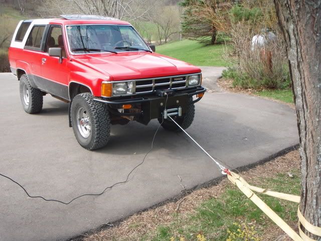


The last picture is at our football field for the demonstration day. The truck was in position to pull a football sled with most of the class on it. The demo was successful and nothing broke!
The last picture is at our football field for the demonstration day. The truck was in position to pull a football sled with most of the class on it. The demo was successful and nothing broke!
05-10-2008, 08:31 AM
#59
Registered User
Thread Starter
Join Date: Jun 2005
Location: Minnesota
Posts: 378
Likes: 0
Received 0 Likes
on
0 Posts
Well I guess it is time for a concluding post to this project. The bumper has held up well to some road abuse as well as light winching, and can be considered a success. I ended up achieving an A in the class, so it was definitely worth the time put into the project.
It has been a tough but fun 4 years of engineering, but I am glad to have graduated. It has been a busy few weeks getting ready to move halfway across the country to WV, arranging housing......oh yeah, and buying a new FJ Cruiser The wait until Mon or Tues is going to seem like forever!
It has been a tough but fun 4 years of engineering, but I am glad to have graduated. It has been a busy few weeks getting ready to move halfway across the country to WV, arranging housing......oh yeah, and buying a new FJ Cruiser
The wait until Mon or Tues is going to seem like forever!


