
IFS - Control Arm Failure, What The Heck
 Apr 18, 2015 | 12:32 AM
#21
Registered User
iTrader: (1)
Joined: Apr 2009
Posts: 13,381
Likes: 100
From: I live in New Tripoli Pa out in the woods
From your testing if it had not failed in the heat effected zone it would have failed some other place.
Hard to tell from pictures but it looks to be it was welded at to high a current for the material in question .
The over penetration should have been caught then we all have bad days .
It could have been get it out the door no matter what.
Then it is a hard call to make from pictures.
Hard to tell from pictures but it looks to be it was welded at to high a current for the material in question .
The over penetration should have been caught then we all have bad days .
It could have been get it out the door no matter what.
Then it is a hard call to make from pictures.
Apr 18, 2015 | 05:41 PM
#22

What I see is a really HOT weld technique combined with a double poor choice of material for the ends.
It really looks like a mall crawler quality setup rather than a hardcore wheeler, rock jumper affair.
The cam bolts are junk after about one winter, the road salt and moisture will corrode any un-protected metal in short order and seize up bolts very quickly. I use excessive amounts of anti-seize any time I open up a bracket. So I would just ignore the cam bolts, they are a lost cause.
Looks like something I could use for a snow wheeler her in NY.
Apr 19, 2015 | 07:03 AM
#23
Thread Starter
Registered User
Joined: Jun 2009
Posts: 977
Likes: 4
From: Southern California
Since I got this kit second hand and just used it for mock up testing, it served a purpose. It is also a good educational tool. I still have all the components but eventually they may get scrapped.
Jul 4, 2015 | 08:51 AM
#24
Thread Starter
Registered User
Joined: Jun 2009
Posts: 977
Likes: 4
From: Southern California
Thread update. I received a phone call back in May from the guy who bought the truck. He introduced himself and explained that he had bought a truck with a Blazeland Long Arm kit recently installed. He was wanting to know what his options were for shock upgrades. He said bought a set of Bilsteins, part # 24-185745 that are listed to fit on the Blazeland website. When he received the shocks they didn't look right for his upper shock attachment point. At first I was a little bit confused by his description so I asked him to send me some pictures to try and help explain his situation.
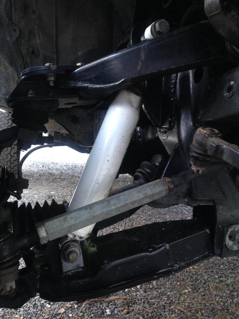
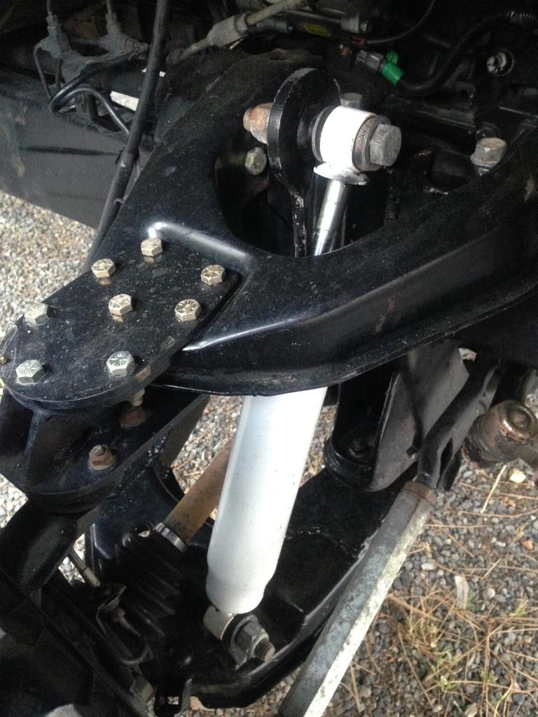
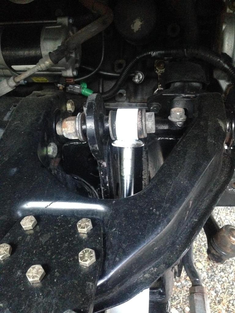
After seeing these photos it made perfect sense. With the previous lift kit the factory upper shock tab had been cut off and a double shock mounting bracket had been welded into place. This custom configuration uses a shock with the eye to eye rod end mount, not the factory configuration of eye to pin rod end mount.
We discussed options ranging from restoring the factory upper shock tab, to creating an adaptor bracket, to installing a set of shock hoops. I explained that due to the limited space resulting from using a factory UCA, locating a shock within the pocket of the UCA required a 2.0 shock body with the can mounted down. This way as the UCA droops the shock body sits low and below the UCA so the shaft, with its small diameter, clears the UCA. He was wanting a higher end style shock with a 2.5 shock body, can mounted up. I suggested the easy solution was a set of my shock hoops to locate the shock behind the UCA. He said he was a fabricator and was going to build some shock hoops. He said he might also build a new set of tubular UCAs.
As far as him knowing the suspension history of his truck, he said the previous owner didn't talk about it. I got the impression he didn't care, he was just perplexed about not being able to bolt on the recommended Bilsteins. I mentioned this thread and thought it would be cool if he would find it and up date us on how things progress. Hope he chimes in, I am interested in seeing what he comes up with.
Oct 17, 2015 | 10:19 AM
#25

Registered User
Joined: Dec 2011
Posts: 93
Likes: 0
I think one of the biggest problems is the small surface area for that pivot to carry the load and the direction of the forces affecting it. Anytime I have 2 tube welded together they get some kind of gusset. Had that had a wrapped gusset or one on each side I don't think that would have happened.
Dec 3, 2015 | 06:55 AM
#26
Registered User
Joined: Feb 2015
Posts: 15
Likes: 0
Stock cage

Race cage

and finally an exploded view of the assembly (with race cage)

My whole point to this is that you CAN achieve 15"+ of travel from a IFS 4x4 truck.
here is a picture of the front of my prerunner truck using this setup with 3.5" over arms:
 Dec 9, 2015 | 09:46 AM
#27
Thread Starter
Registered User
Joined: Jun 2009
Posts: 977
Likes: 4
From: Southern California
Right on, we all appreciate the additional information!
Keep in mind I was just going off the CV assembly that came with the busted up kit. It originated for control arms of +2" and the metal to metal travel number for this kit was 10-1/2" as stated earlier in this thread. When I lengthened the center bar to work with my mock up at +6" per side control arms, with pivot relocations, and narrowed diff assembly I was able to get 14.625" of travel. Keep in mind this modified CV center bar is now closer to a +7" longer center bar.
As for achieving 15" of travel with a +3.5" control arm and +3.5" longer CV center bar I am still skeptical. Yeah, the "930 Prepped CV joint" should be an improvement, but going from a T-100 CV (12" travel) to a 930 CV (15" travel) with the same length center bar is hard to believe.
Don't take this the wrong way but I would check your numbers. Position your truck on Jack stands with the suspension at full droop and take a measurement from the ground plane to the center line of the spindle. Then do the same with the suspension at full stuff. Do this without limit straps or bump stops to get the metal to metal measurement. As you do this take note of the CV operation but you must also include checking the related components such as steering links and ball joints for bind. Then reintroduce the bump stops and limit straps to find the usable travel. I suspect if you go through this you will be surprised on your findings.
A standard formula +3.5" long travel built around a T-100 CV is going to be limited to 12" of travel metal to metal. With upgraded 930 CVs I could see it hitting 13" but 15" is unlikely.
Last edited by BlazeN8; Dec 10, 2015 at 08:57 AM.
Dec 10, 2015 | 08:43 AM
#28
Registered User
Joined: Feb 2015
Posts: 15
Likes: 0
I will try to find the pictures I took when building the front of my truck (tape measure included) cycling that much travel.
Dec 10, 2015 | 09:14 AM
#29
Thread Starter
Registered User
Joined: Jun 2009
Posts: 977
Likes: 4
From: Southern California
That would be awesome! I checked out your build threads both truck and 4Runner, very nice. If you do an update on the truck with the additional information I can view it there, no need to carry on the banter with this thread.
From your build truck thread I could see your running uniball upper but cant tell about the lower weather its a uniball or a ball joint. I've found that the stock lower ball joint binds at 13". I also know even King Kong steering binds way before you 15" If you can address those items too that would be great.
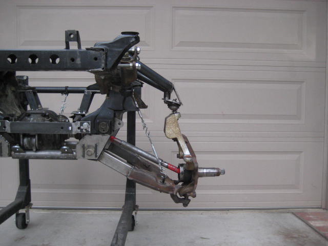
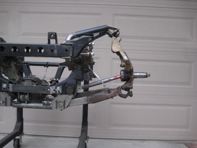
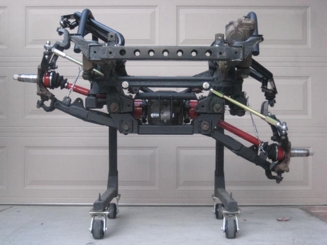
Here is another picture of the Mega Travel Pro 4 sustem I am running on my 1986 4 Runner. Have you been following this thread?
From your build truck thread I could see your running uniball upper but cant tell about the lower weather its a uniball or a ball joint. I've found that the stock lower ball joint binds at 13". I also know even King Kong steering binds way before you 15" If you can address those items too that would be great.
Here is another picture of the Mega Travel Pro 4 sustem I am running on my 1986 4 Runner. Have you been following this thread?
Dec 10, 2015 | 02:01 PM
#30
Registered User
Joined: Feb 2015
Posts: 15
Likes: 0
That would be awesome! I checked out your build threads both truck and 4Runner, very nice. If you do an update on the truck with the additional information I can view it there, no need to carry on the banter with this thread.
From your build truck thread I could see your running uniball upper but cant tell about the lower weather its a uniball or a ball joint. I've found that the stock lower ball joint binds at 13". I also know even King Kong steering binds way before you 15" If you can address those items too that would be great.
Here is another picture of the Mega Travel Pro 4 sustem I am running on my 1986 4 Runner. Have you been following this thread?
TC's King kong (in conjunction with the "caddy" idler arm and my own tie rods) does not bind way before 15". I used to have their 4WD race kit on a different truck (15" of travel too) and ran the same steering setup without a hitch. can you enhance a little bit on what was limiting travel in your experience?
That picture is of a BJ. I had just bolted them in as I had a uniball failure (due to my own poor BJ to uniball design) the day before.
Dec 14, 2015 | 09:50 AM
#31
Thread Starter
Registered User
Joined: Jun 2009
Posts: 977
Likes: 4
From: Southern California
Steering link I built for a +3.5" over stock was binding at 13" at the outer Rod End. I was using the TC bolt kit and heims but with my custom machined adjusting sleeves. The TC 2WD Race kit that gets 15" travel uses all the same but is for a +5" over stock. This setup also uses a 1/2" bolt reduction with a tapered fitting at the steering arm. Because of the bolt reduction you need the weld on double sheer at the steering arm. I just assumes the added length of everything was how TC got the additional travel. The 10" wider track width (Race design) is something I am trying to avoid since I want it to be streetable.
In the above photo you can see I changed the attachment points on the center link as well as on the 4" spindle spacer to achieve working steering links.
In the above photo you can see I changed the attachment points on the center link as well as on the 4" spindle spacer to achieve working steering links.
Dec 14, 2015 | 10:21 AM
#32
Thread Starter
Registered User
Joined: Jun 2009
Posts: 977
Likes: 4
From: Southern California
To step back on this conversation, as in the big picture, from my perspective, my R&D in a carefully controlled environment just wouldn't allow the travel numbers you found for a +3.5" over stock design and its frustrating.
A 930 race prepped inner CV could be the difference between what I was using. But the outer Toyota joint binds at 13" unless that was changed too.
The Toyota Lower BJ also binds at 13" and what my research has found so does the uniball upgrade. The uniball upgrade is said to be a strength enhancement not a angle increase.
The outer rod end using heims with 1/2" bolt reduction binds at 13" as well.
Lastly when I was using a 3.0" coil spring with the shock located inside the UCA pocket will result in the spring being pinched between the UCA and the frame a +3.5" The TC race kit has 1.5" more control arm length here allowing the added clearance. I see your not running coil spring so moot point. The TC race kit also eliminates the factory bump stops and bump stop frame attachment allowing additional travel. I saw on your build you eliminated factory bump to and are now running air bums. Very nice.
As for me be doubting Thomas by questioning your design I hope its not taken personally. I'm just trying to advance my IFS design. I've tried running the numbers for similar configurations and it has not worked out in the areas I stated.
Last edited by BlazeN8; Dec 16, 2015 at 05:04 PM.

Thread
Thread Starter
Forum
Replies
Last Post
FS[GreatLakes]: Toyota collection part out
88sasturbotoy
Axles - Suspensions - Tires - Wheels
3
Jan 30, 2026 01:57 PM
kirkrunner
86-95 Trucks & 4Runners
2
Jul 27, 2015 07:59 PM


