
Auxillary 12VDC Outlets in 3rd Gen console
 Jul 5, 2010 | 08:39 PM
#1


Auxillary 12VDC Outlets in 3rd Gen console
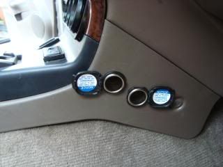
 Well I have been contemplating this mod for awhile but was over come by other events. Now that my axle seal job is on hold until I can get some assistance in determining the status of the bearings, I decided to use my time this holiday weekend by adding extra outlets to the center console.
First flight 3rd gens (96-98) were plagued with many interior deficiencies. One of which is the sore lack of power outlets. thsi was pretty much remedied in the 2nd flight (99-02) with the addition of two more power outlets at the base of the radio bezel. So with that in mind. Here is my write up on installing additonal OEM power outlets.

Auxiliary Outlets
Another in the Mods for Dummies Series.

This mod is for adding factory Toyota 12VDC power outlets to the center console of our 3rd generation Toyota 4runner. The first flight (96-98) was ‘under powered’ when it came to power outlets. Toyota helped in second flight (99-02) 4runners when they upgraded the radio bezel and installed two additional outlets. With this mod you will be able to add two additional factory Toyota 12VDC outlets to any 3rd generation 4runner (96-02). While this write up deals specifically with 96-02 4runners, you can use the basic disassembly instructions for removing factory outlets for installation in various configurations on most any year 4runner, truck or Landcruiser. Use caustion when installing these outlets on other then 3rd gen 4runners. Remember, this was installed specifically on a 3rd generation 4runner. Please read the following:
 Disclaimer: This write up is for educational purposes only. Any use or application of this procedure is done so at the risk of the installer/owner. The author and YotaTech are not responsible for any modifications done to any vehicle using these or any other related procedures contained in this write up. Use of these and any other related procedures, drawings or photographs or instructions are done so at your own risk. Descriptions and photographs are the sole property and copyright of the author ritzy4runner and may not be copied or distributed without written consent. Links to this article may be allowed but are protected by all US copyrights. Use of specific products along with any photographs or descriptions of any products or components remain the copyrighted or trademark property of the copyright or trademark holder and is not an endorsement of any specific company or items.
While this is not a complete list of tools you may need, these are recommended:
7mm nut driver
Crimping pliers
3/8 drive electric or cordless drill
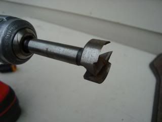
1” drill bit (fostner or wood)
Utility knife
#2 phillips screwdriver
Small flat blade screw driver �” tip
Needle nose pliers
Recommended Supplies:
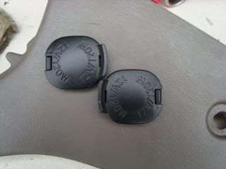
1 or 2 - OEM Toyota 12vdc outlets with harness
2 – 16/18 gauge wire splices
1 – 16/18 gauge spade female connector (for power wire)
1 – 16/18 gauge split loop connector (for ground wire)
3 ft – 16 gauge wire (any color for power)
1 ft – 16 gauge wire (black preferred for ground)
Recommended Mods previously installed:
Auxiliary Fuse Panel
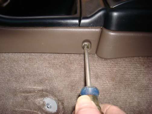
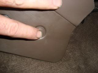
Begin by removing the right side lower center console plastic panel. Remove the Phillips screw at the back closest to the seat.
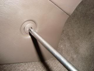
Remove the panel holding pin by pressing in the center with the Phillips screwdriver. It will make a ‘click’ sound.
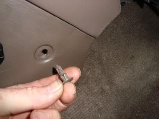
Remove the pin with your fingers.
Grasp the base of the Radio bezel and lift slightly. Just enough to allow the shifter bezel to be lifted Remember, the radio bezel is still attached with screws so don’t lift toomuch or you will break something!
Grasp the base of the side panel and attempt to move the panel towards the firewall. The large end of the panel along the upper edge has two clips that hold the panel in place. The one closest to you has a clip edge. You should be able to see it if you pull the panel outward slightly then use your finger to lift the clip. You should be able to move it slightly towards the firewall now and you will most likely need to also pull the center console bottom edge outward so you can free the narrow rear end of the panel free as well. With the panel free we can begin to prepare the panel.
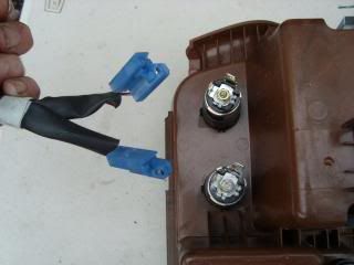
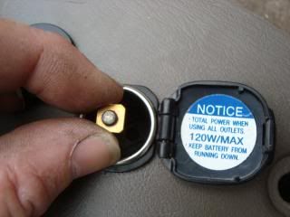
If you have your outlets you will need to disassemble them for installation. You can perform these steps at your bench or in the field. If you are going to remove these from a radio bezel proceed as follows:
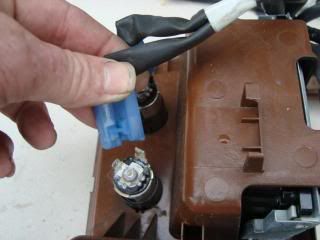
Remove the wire harness from the outlet contacts. It will just pull right off with a slight bit of back and forth movement.
Using the 7mm nut driver, remove the center contact lock nut and lock washer. Save for reinstallation.
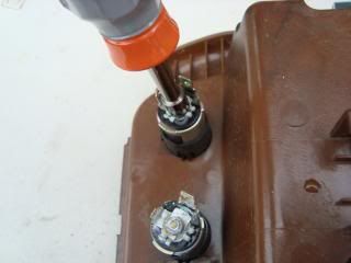
The center pin bolt will fall into the tube so remember to retrieve it after removal of the small and large pins. Remove the small pin, this is a black washer with the small pin attached to it. Set this aside
Remove the large pin and set aside.
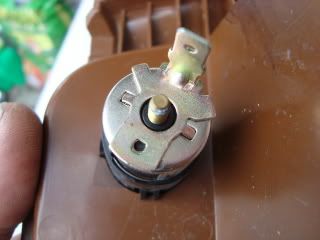
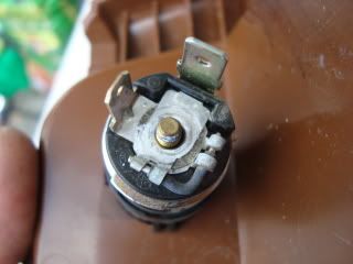
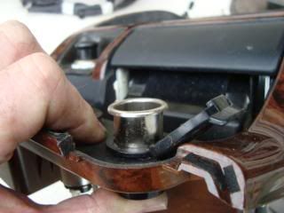
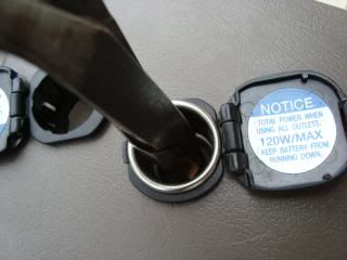
Next we will remove the outlet tube. This is the metal cylinder of the outlet and retained in position in the outlet collar by a small wedge located near the rear of the tube.
Using the small flat blade screwdriver you will need to press down the back edge of the wedge. The only potential issue here is if you are too close to the edge, when you apply pressure to the tube to retract it, the tube will be stopped by the blade so ensure you are just back from the edge enough to press it downward. This will take some pressure, but as you press down on the wedge push the tube from the back side toward you. If you feel it move just a tiny bit you may have it free enough to continue pushing the tube until it clears the collar
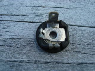
After removal of the tube, you can remove the collar. The collar is retained by two press clips. You can press in one side then the other using either your fingers by just squeezing them inward or using the small blade screwdriver. Push the collar from the back and it will slide out of the bezel mount.
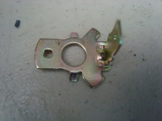
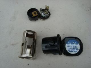
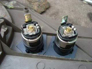
You should now have all the outlet parts as shown:
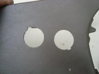
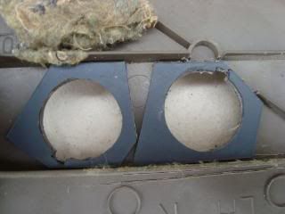
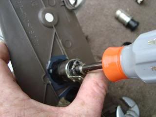
Obtain the 1” drill bit and drill.
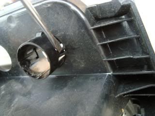
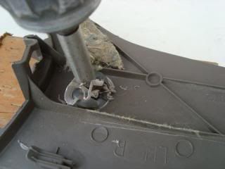
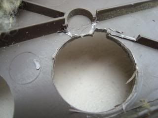
The panel has molded support ridges on the back side to give it strength. We will use these for location of our outlets. Center the drill bit about an inch from the edge and drill the first hole. This is not very thick so drill slowly until you are almost completely through.
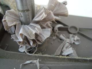
After the holes are drilled through, clean up the edges with the utility knife. Test fit the collar to orient the cap opening so they will not interfere with each other. I opted to have them so that when they closed, the cap flips would be just out of the way of each other.
Pre-fit the first collar and note where the orientation ridge is. Mark this with the utility knife then notch it out. Repeat this for the second collar so that you end up with two holes ready for the collars.
As the panel is � the thickness of the radio bezel, you will need to make two shims to firmly anchor the collars in position. I chose a plastic plant flat. You can get this from most any store with a nursery department (plant nursery! LOL). Find one that is pliable and not hard plastic.
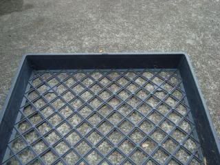
Cut off an edge strip about 4 inches long. Drill two 1 inch holes. Be very careful when you do this. I had some issues at first and was only able to start the cut and ended up finishing the holes with the utility knife. Remember to also make the alignment notch.
Flip the panel over to the back side. You will notice in my configuration in order to obtain the orientation of my covers to not be conflicting with each other, one of my alignment notches was right at the center of the support ridges. I then used the utility knife to cut away only that portion of the support ridges that would interfere with the shims.
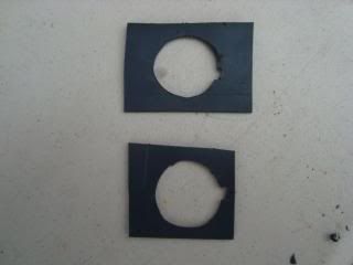
Next we will fit the shims to the panel so as to provide the maximum support. We will trim them to fit each collar.
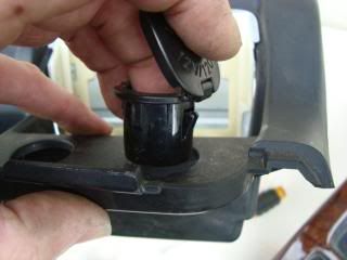
Holding each shim in place insert the collar into the panel and the shim. Press the collar firmly into position ensuring the collar hold downs snap over the shims completely. Repeat with the second outlet.
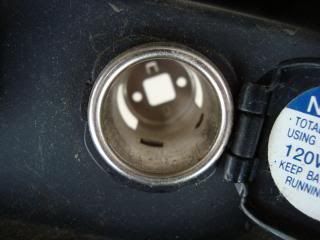
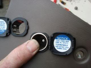
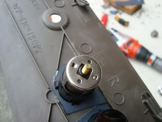
Flip open the outlet covers. Take an outlet tube and the inner outlet center piece, it is the round black piece of plastic that was in the base of the tube. Note the square base, insert the base to align the square base with the hole in the bottom of the tube.
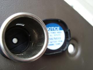
NOTE: This is very important! Ensure the small round hole in the tube is aligned with the right side of the tube as you are looking at it. The flip cap will be right side up when you do this.
Firmly press the tube into position. Ensure that the small hole is to the right and the edge is centered on the tube cutout. Push completely in the collar until flush. Check for alignment and that the wedge is seated.
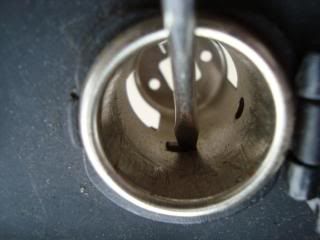
Locate the center metal pin/bolt. Drop into the tube and using a pair of needle nose pliers orient the pin into its seat.
Using your finger, hold the pin in position.
Take the large pin.
Orient it so the small side locator pins fit into their respective locations on the base of the tube.
Place the small pin with the flat side of the disk towards the large pin. This will place the small pin to the left of the large pin.
Place the lock washer over the bolt and then the locking nut. Use the 7mm nut driver and firmly screw on the lock nut.
Repeat for the second outlet.
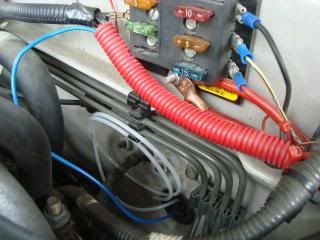
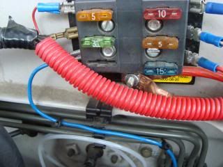
As I mentioned at the beginning, I have the Auxiliary Fuse Panel mod. If you have not done this mod, it is one of the best small projects you can possibly do and it is under $20. You will be able to provide non-ignition base power to other mods. If you do not have this mod, then you will need to locate a power source to tie into for the needed power connection. I am using the Aux Fuse Panel.
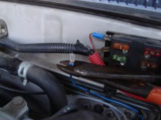
Route the 3 ft piece of 16 gauge from the engine bay through the rubber plug on the left side of the firewall. It is about 2” in diameter and comes into the cabin just above the accelerator. I inserted the end into another wire loom just to keep it out of the way and also to know about how much wire I would need to make the connection to the Aux fuse panel.
Be careful when routing this wire in the cabin. I found a route over the top along the ducting so I was able to have it out of any areas that could be a cause for entanglement. Use you own best judgment for your routing. I ended coming out at the base of the radio bezel.
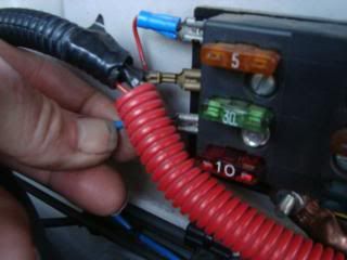
Select an empty location for the power attachment on the aux fuse panel. Strip the end and crimp the spade female connector.
Install the new connector on the corresponding fuse panel male spade connector.
Tie wrap the wire in place to keep it neat and out of the way.
I used the OEM harness from the donor vehicle that I got the outlets from. There will be 4 wires total. Two green and white and two white and black. The green wires are the hot side. Strip the green wires ends and install into a single wire splice and crimp.
Do the same for the ground side wires. Next pull the power wire through until you have about 6-8 inches beyond the panel mounting location. Cut and strip the end. Insert this into the power splice end and crimp.
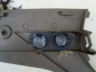
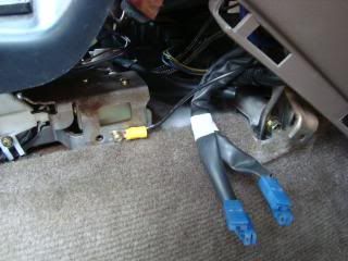
Take the black ground wire, strip one end and crimp on the split end connector. Locate a suitable ground. I chose the small brass looking phillips screw located near the shifter.
You may want to leave the entire piece of ground wire as it is, if so , strip and splice this end into the ground wire splice in the harness. Tuck the excess wire into the base of the console.
Attach the connectors to the outlet pins and install the panel. The install is basically the reverse of how we removed it. When installing the panel lock pin near the front, be sure to push the center piout so that it is sticking out the front side of the clip, just push the entire assembly into position flush with the hole and push the center pin in until it clicks
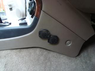
Install a 10 amp fuse in the Aux Fuse panel and you are ready to use your new outlets.
Last edited by Ritzy4Runner; Jul 7, 2010 at 06:14 AM. Reason: correction and update

 Jul 6, 2010 | 10:05 AM
#3
Contributing Member
Joined: Mar 2003
Posts: 11,334
Likes: 0
From: COTKU,Ontario,Canada
Another well done mod from Ritzy...
FYI in previous gens there is a metal radio/dash support member behind the side of the radio bezel so that location might not work for you if you choose to do this mod.
FYI in previous gens there is a metal radio/dash support member behind the side of the radio bezel so that location might not work for you if you choose to do this mod.

Thread
Thread Starter
Forum
Replies
Last Post
matmattmatthew
86-95 Trucks & 4Runners (Build-Up Section)
10
Feb 9, 2021 04:15 PM
runnermedic
95.5-2004 Tacomas & 96-2002 4Runners
13
Sep 21, 2015 05:20 PM
reallynotamechanic
86-95 Trucks & 4Runners
1
Sep 11, 2015 11:52 AM
icentropy
86-95 Trucks & 4Runners
7
Sep 10, 2015 05:03 AM
Highlander Giant
General Vehicle Related Topics (Non Year Related)
0
Sep 8, 2015 06:46 PM


