When you click on links to various merchants on this site and make a purchase, this can result in this site earning a commission. Affiliate programs and affiliations include, but are not limited to, the eBay Partner Network.
GM ignition Conversion question (LX301) for single wire distributor.
1977 Hilux, 20R and i've got a misfire in it and have all the for the GM ICM conversion but I can't find the wiring diagram for my single wire distributor. Its a simple straight forward conversion and I after 2 days of fiddling around and finding parts I've got it mounted and the wires made for it. But now I'm realizing that I don't have the wires from the distributor.
There's a video on youtube with a guy who's done it to a 78 but he has two wires coming from his distributor. I read about how to do this about a year ago and finally have the time to do it but can't find the same resources as I did last time. Can someone link me to the best conversion guide? I"ve been reading forums all day.
First thing that slowed me down is the black wires (photo 1). the small one uses a bullet connector and goes into the cab. Its not in the diagram. The diagram suggests that the negative on the coil comes from the igniter only. (photo 2)
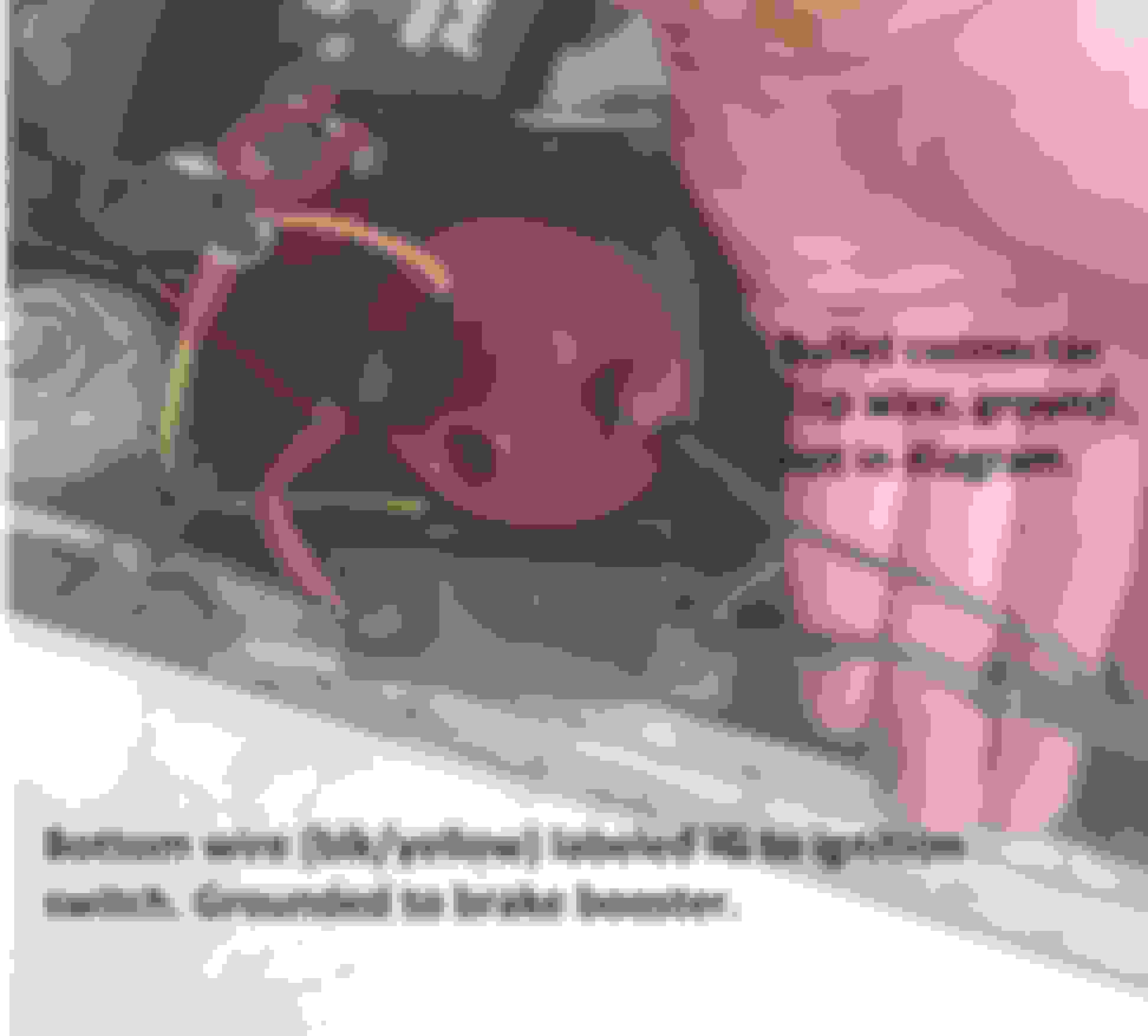
Second, the large black/yellow I assumed was ground that goes to the ballast resistor is labeled IG in the diagram. I tested it to see if it was ground and it has continuity with the brake booster. Same with the negative on the coil. I didn't disconnect the small bullet connector to see if it was still grounded at both. I read somewhere online that the Black/Yellow is the positive.
I've also noticed a static charge on the body recently and was wondering if this whole problem as well as the misfiring could be related to a bad ground or chewed through wires?
Here's the mounted ICM waiting to be installed. Got a copper core heat sink for a computer CPU from ebay for $5, igniter for $8. Marked the location and drilled some holes. First for the plastic alignment tabs on the ICM, then some small one's to mount it. I used #6 sheet metal screws and an impact driver to tap the holes and mount it. Went through a few screws as the heads would bust off when tapping. One broke off so close to the surface I had to turn the ICM around and make new holes. This was particularly thick and tough and the stainless screws break less often. Wal-mart screws break much easier than the same one's from home-depot.
Using two 2" conduit clamps from Home Depot ($2 each) to mount the coil and ICM. The old ICM is permanently attached to the round bracket on my truck and the coil clamp from the store is around $9. They wanted 17 cents for a washer at home depot, so I found a 1977 penny from the change jar and made one.
Since 3/8" tabs are less common the auto store wanted $7 for a 10 pack. I just turned a spare 1/4" male around and soldered it. I considered soldering all the connections but want to make it road-side-repair ready. I did solder all the wires to the connectors and insulated them with shrink wrap.
Does anyone know that the W and G letters represent? Web forums suggest B to be Battery (+) and C for Common (-) but no one seems to hint what the others are--Just that its a 50/50 chance of working properly.
But because my distributor does not have two wires it appears I'm at a stand still. I also wanted to get more probing done on a few things before I just wired it up. My meter leads broke the other day so I have to set the meter on a ground (tricky to always make contact) and can probe with the red lead (new leads are in the mail).
To reiterate, is the large black/yellow positive or negative? Should it have continuity to ground when the key is out and battery off? Links?
Also, it seems to be rusting more recently. I vaguely remember someone telling me when i was younger that sometimes older vehicles need a zinc block (or some metal) to be grounded to in order for it to decay before the rest of the truck. Does this sound like something I might be interested in? My wiring harness is pretty tore back, spliced all over the place by a serious amateur.
Was probing around with the limited capacity that I have and built a test light. I'm certain now that there is a short in the system. The test light shows the black/yellow wire to be the + wire engaged by the ignition switch. Just before the ballast resistor someone spliced a blue wire in by stripping it back and crimping onto it and using electrical tape. When the ignition switch is disengaged at the steering column connector the ground continuity is still there. its not coming through the ballast resistor because I disconnected it there too.
The blue wire is the one that I need to follow and see where it leads. Unfortunately its one of two blue wires exactly the same and they disappear into the tape under the harness. So I'm gonna have to cut that open to find out where it leads and if its the source. or not. There is one potential that is a bullet plug that would fit the small capacitor that sits connected to the voltage regulator. It is ground but not quite the same shade of blue. Gonna have to cut the wiring harness a little to see if the wire is just spliced into another wire or not. That multiple-short-wires-to-make-one-long-one technique seems to have been standard operating procedure with the last electrician.
Also, the ballast resistor seemed to be getting very hot the first time I ran it this morning. I didn't change anything and it was running normal. I shut it off immediately and let it cool off, did some probing and checking of wires and ran it again but didn't change anything and it ran just fine. Could it have been hot just from the key being on while not running?
The W and G lugs on the module go to the distributor. Are you sure that the distributor only has one wire, as the wiring diagrams shows two. That may be one problem, one lead broken off at the dizzy. I has been said that it runs rough after setting the timing, try switching the leads on the module. There are numerous posts on the internet on how to do the conversion. There is is an explanation in this link on Pirate4x4 Post #82. Hope you get her done.
Before I do the conversion I wanted to trace the reason there is ground continuity on the black/yellow wire but is +12v.
The blue wire goes to a bullet connector of nothing. The black/yellow wire goes right into the interior and appears to be connected to the ignition switch. I disconnected it and at the ballast resistor and expected it to be isolated but they were both still making connection with ground. The wiring harness is all taped together so I can only assume its the same wire. its fatter than the rest, however there are other black/yellow wires within the harness but smaller diameter. I don't want to chop the wiring harness inside just to see if its spliced or damaged unless I have to.
The small black wire that is connected to the - of the coil goes into the interior, connects with some wires that go to the AC, possibly back out to the AC pump, but that wire did not have continuity. The wire that goes into the interior is not ground continuous, but the one from the coil is. Not sure why they would hook a ground wire up to the coil because the test light on the coil always pulsates instead of solid light when the vehicle is running.
My wiring diagram suggest one wire and a ground. I have the one wire but it doesn't go directly to the coil like the diagram suggest. The wire on top of the distributor is part of the old igniter. Should I just run a ground from one of the bolts on the back or vacuum advance? it does have a wire clip on one.
Where are the wires suppose to go? The photos I see online all have the wires coming out of the distributor. I just have the post for something to attach to (igniter)
The Black/Red wire should have 12v battery power all the time. You might take the steering column cover off to get to the back of the ignition switch and check it separate from the harness wiring.
In checking my Ign Switch, I have continuity at the different positions as following:
Key Off position = Black/Red and Black/Yellow
Acc position = Black/Red and Blue/Red
On position = Black/Red, Black/Yellow and Blue/Red
Start position = Black/Red and Black White
This wiring diagram shows 2 wires at the dizzy, no color specified. Should also have a coil wire from the igniter and the center of the dizzy cap. https://www.autozone.com/repairinfo/...00c1528004d7c3
You might look at the dizzy manufacturer's plate and see if it in fact a 20R dizzy.. Just some suggestions that might help.
I looked more extensively at the wiring diagram in my haynes. It has multiple wiring diagrams depending on a few things, mine appears to be the RN series.
I had the fuse panel off to trace the Blk/ylw wire to isolate it but found they have a white/red wire on the same circuit as the engine fuse. My bottom three fuses also have ground continuity. It was too windy to work on it so I didn't get far. I need to keep notes so I can continue without retracing my steps.
If you look at the second image of the first post you'll see the single wire distributor diagram is exactly like mine.
Ok. Just noticed the your distributor has points and not a electronic module. I'm not sure that the GM conversion will work with a point type system. Maybe there is conversion kit for your distributor, available somwhere.
Ok. Just noticed the your distributor has points and not a electronic module. I'm not sure that the GM conversion will work with a point type system. Maybe there is conversion kit for your distributor, available somwhere.
Pertronix is widely used in the musclecar world for drop-in ignitors to eliminate points. Their website does show some Toyota options as well. www.pertronix.com
Pertronix is widely used in the musclecar world for drop-in ignitors to eliminate points. Their website does show some Toyota options as well. www.pertronix.com
They don't seem to list my truck. I was looking at that option before when I was considering the upgrade. I can't really afford to keep buying new stuff for it at the moment.
I fixed the chewed up ground wire in the distributor and cleaned the points and cap with 320 grit sandpaper. Afterward it was giving me trouble starting so I popped open the distributor and checked the gap to see if maybe I had re-positioned them while replacing the wire but it was spot on. Put the cap on and it started right up.
While cranking it and it didn't start it built up a huge amount of static electricity and gave me a pretty strong shock. What is causing this? Its been doing it for awhile, but this time was the strongest yet.
Sounds like you have a bad coil. If they start breaking down, they usually will send the charge to ground instead of through the distributor and spark plug. I had one breakdown on me in my California Bug. I started loosing power , pulled off side of road, lifted hood and spark was arching all over the engine bay. Limped home
Just and idea. If you have a spare you might swap it out and see what happens.
I bought a new one from ebay for the conversion but it turned out to be bunk (was swapping single parts at a time to prevent confusion if it didn't work). I was going to test the coil yesterday but had to fix my meter leads first and the sun went down before I could get out there again.
Voltage drop across the ballast resistor is 11.53 down to 4.96V (6.57V drop). I think I read that the coil should be getting around 6V.
I don't know if you got this fixed yet, but here's my 2 cents worth. I am likely the guy that posted the conversion video on Youtube that you saw.
You definitely have the older style points distributor. This is confirmed by the single wire coming from it. Later distributors that have the pickup coil instead have 2 wires. 1977 was the last year Toyota used the points distributor on the 20R, so your distributor may be the original so it could also be worn. The electronic conversion doesn't really work very well with the points distributor, as the points are subject to arcing, corrosion & wear over time, so the "break" signal they generate for the coil will be uneven. The whole idea of adding an electronic ignition module is to eliminate the points, for a more reliable spark signal & no points cleaning & adjustment.
An earlier suggestion that you add a Pertronix unit is viable, but not the best solution. As you found out, Pertronix does not specify a unit for Toyota, so there would be a lot of modification & fiddling in trying to get it to work correctly.
The best solution is to get a later style distributor ('78 & up 20R) that has the pickup coil inside instead of points. Best deal available on one of these I've found is Rock Auto: https://www.rockauto.com/en/catalog/...stributor,7108
You can also get these from local parts houses, but they also usually have to order them in (not a regularly stocked item), the price is $20-$50 higher & they will sometimes want to charge you shipping on it as well.
You will also need about 3 feet of shielded, 22 Gauge, 2 conductor, alarm system wire, to hook up the pickup coil to the ignition module, plus some female spade lugs to fit the tabs in the "green plug" on the distributor (pickup coil wires) & the tabs on the module. You'll have to build this harness but since I see you are OK with soldering you shouldn't have much trouble with it. You could use regular wire at least 22 gauge thickness (do not go smaller) but there could be interference that could disrupt the pickup coils' signal to the module; that's why the shielded wire is better. The shielded alarm wire is available for reasonably cheap at almost any home improvement store (Home Depot, Lowes, etc.) This wire usually has a red & a white wire. The pickup coil wires are also red & white. Red wire goes to "G" terminal on the GM module, White wire goes to "W". Don't get them backwards or the pickup coil will be "out of phase" & could cause run problems.
If you have any problems locating the alarm wire locally direct message me; I have some new spare wire on hand that I could mail to you (I'm in Florida).
You DO NOT NEED a ballast resistor on this setup. The ballast resistor is only there to help save your points (burning from over-arcing @ full battery voltage), so since you will be eliminating the points, the resistor isn't needed. Keeping it in the circuit on this conversion will only cause you problems & could actually reduce performance.
This coil has the correct resistances to work well with the HEI Module, & that is a critical factor in this conversion. I tried a cheaper Chinese made coil (Spectra Premium C624) before on this setup & the coil failed within 8 months & fried 3 ignition modules before I figured out what was going on. The resistance on it went too high as it heated up. The HEI Modules can be sensitive to wide variations of resistance (or high resistance) in the coil, & the cheaper coils on the market are notorious for doing that as they wear. Go for quality the first time.
That's about all I can think of t the moment & I hope it is of some help to you.

 Apr 25, 2019 | 10:57 PM