4307's 2004 Tacoma Build-Up Thread
 11-16-2008, 06:36 PM
#1
Registered User
Thread Starter
Join Date: Nov 2008
Location: Ontario
Posts: 89
Likes: 0
Received 0 Likes
on
0 Posts
G-Day!
I'm 4307 and this is my Canadian flavored Taco.
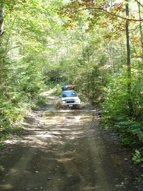
The purpose of my build....... " head for the bush! " Overland style.
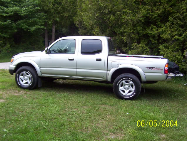
The project is a Silver, 2004, D-Cab, TRD. Bought it off the lot, new. Actually it was one of three last, new, late 04 D-Cabs available in Canada, before the 05 model change.
I've been lurking in the shadows of TTORA for some time now and occasionally occupy a corner at Expedition portal and now YotaTech.
I've been driving the truck with stock suspension since day one. I'm a cheap ass. I chose to drive the truck, stock, off road and push it's limits. So far I'm very impressed, errrr! Except for the BFG Rugged trails! They are, what they are! Oh did I mention I was a cheap ass?
Anyway, the real reason it's still stock is budget. I feel more comfortable paying down 3/4's of the payments and keep the Kilometers down to a realistic level until I get the missing parts for the suspension, gears, tires. (sitting @ 55,000km right now).
Before the truck purchase, I've been buying tools, building up a home fab shop (in the basement). Tool shop is my other, other hobby. Now I have the main tools. Its time to build. Building is half the fun for me.
O.K. the cheap ass thing isn't totally true. I'm actually sitting on a pile-O-parts. There's a few goodies in the pile. I'm cheap for not putting them on yet.
ARB bull bar
Donahoe Coilovers
63' Chevy leaf springs ( junkyard specials.... rebuilt them, post to come)
255/85R16 Maxxis Bighorns
Ammo can on drawer slides
Leer canopy.
Thule roof rack on the Leer cap
Yakima roof rack over the double cab.
Custom rear bumper....
Hi-lift jack and shovel
KEW 8000 budget winch ($300 Cdn). Identical to the Mile Marker PE 8000. If it saves my ass a few times it payed for it's self. We'll see how it holds up.
Xantrex Xpower 1200 power inverter.
Blue Sea fuse box
Arb air compressor
8- 5'' rubber sealed tractor lights. Future rock lights.
A couple of 12v remote control modules. hehehe..... this is pretty cool!
Optima Yellow top. (I've been using it quite a bit as a stand alone, recharging on a charger.
Great battery it will be installed in the truck, dual battery.)
Sure Power Battery Isolator
12v lights - for the interior of my truck cap and rear roof rack bar.
Uniden PRO 520 XL CB radio (future home... the ash tray)
K 40 antenna
in cab power inverter.
Cheap rear view camera. hmmm...... should be interesting, Cheapness!
Garmin 60c GPS
Mac GPS Pro software - for Garmin controlled moving map software, Ontario maps @ the
moment. Running this on a Mac 17'' Powerbook, a little big for
wheeling, but great to look at with the help of a co-pilot
(Still in negotiations. Oh Dear can you.......)
Other pile-o-parts for a distant future project....
Dana 44 front Wagoneer shop ornament.
K- 10 brakes, calipers
O.K. I have half the parts for a SAS project. I don't want to think of that right now, it's not in my current budget.
Anyway. This coming spring my truck will see the bulk of the transformation. I still need some parts.
This summer I was able to do some fabrication, My free time went to fabricating instead of traveling. Thats O.K. there is always next year.
Here is a pic of my truck the day after I bought it......
At the beach.....
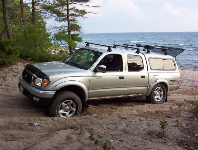
Dorset Ontario....
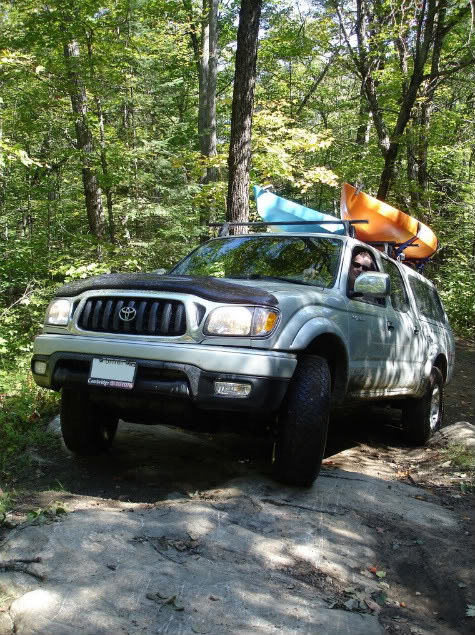
It's still great to get away in a Stock-o Taco.
I can't wait until spring, to glue all this stuff on.
I wish I had a garage, so I can work on the truck during the winter. Oh well. I'll live!
I'm 4307 and this is my Canadian flavored Taco.
The purpose of my build....... " head for the bush! " Overland style.
The project is a Silver, 2004, D-Cab, TRD. Bought it off the lot, new. Actually it was one of three last, new, late 04 D-Cabs available in Canada, before the 05 model change.
I've been lurking in the shadows of TTORA for some time now and occasionally occupy a corner at Expedition portal and now YotaTech.
I've been driving the truck with stock suspension since day one. I'm a cheap ass. I chose to drive the truck, stock, off road and push it's limits. So far I'm very impressed, errrr! Except for the BFG Rugged trails! They are, what they are! Oh did I mention I was a cheap ass?
Anyway, the real reason it's still stock is budget. I feel more comfortable paying down 3/4's of the payments and keep the Kilometers down to a realistic level until I get the missing parts for the suspension, gears, tires. (sitting @ 55,000km right now).
Before the truck purchase, I've been buying tools, building up a home fab shop (in the basement). Tool shop is my other, other hobby. Now I have the main tools. Its time to build. Building is half the fun for me.
O.K. the cheap ass thing isn't totally true. I'm actually sitting on a pile-O-parts. There's a few goodies in the pile. I'm cheap for not putting them on yet.
ARB bull bar
Donahoe Coilovers
63' Chevy leaf springs ( junkyard specials.... rebuilt them, post to come)
255/85R16 Maxxis Bighorns
Ammo can on drawer slides
Leer canopy.
Thule roof rack on the Leer cap
Yakima roof rack over the double cab.
Custom rear bumper....
Hi-lift jack and shovel
KEW 8000 budget winch ($300 Cdn). Identical to the Mile Marker PE 8000. If it saves my ass a few times it payed for it's self. We'll see how it holds up.
Xantrex Xpower 1200 power inverter.
Blue Sea fuse box
Arb air compressor
8- 5'' rubber sealed tractor lights. Future rock lights.
A couple of 12v remote control modules. hehehe..... this is pretty cool!
Optima Yellow top. (I've been using it quite a bit as a stand alone, recharging on a charger.
Great battery it will be installed in the truck, dual battery.)
Sure Power Battery Isolator
12v lights - for the interior of my truck cap and rear roof rack bar.
Uniden PRO 520 XL CB radio (future home... the ash tray)
K 40 antenna
in cab power inverter.
Cheap rear view camera. hmmm...... should be interesting, Cheapness!
Garmin 60c GPS
Mac GPS Pro software - for Garmin controlled moving map software, Ontario maps @ the
moment. Running this on a Mac 17'' Powerbook, a little big for
wheeling, but great to look at with the help of a co-pilot
(Still in negotiations. Oh Dear can you.......)
Other pile-o-parts for a distant future project....
Dana 44 front Wagoneer shop ornament.
K- 10 brakes, calipers
O.K. I have half the parts for a SAS project. I don't want to think of that right now, it's not in my current budget.
Anyway. This coming spring my truck will see the bulk of the transformation. I still need some parts.
This summer I was able to do some fabrication, My free time went to fabricating instead of traveling. Thats O.K. there is always next year.
Here is a pic of my truck the day after I bought it......
At the beach.....
Dorset Ontario....
It's still great to get away in a Stock-o Taco.
I can't wait until spring, to glue all this stuff on.
I wish I had a garage, so I can work on the truck during the winter. Oh well. I'll live!
 11-16-2008, 06:41 PM
#2
Registered User
Thread Starter
Join Date: Nov 2008
Location: Ontario
Posts: 89
Likes: 0
Received 0 Likes
on
0 Posts
Ammo Can Drawer Slide.
Here's a project I finished.... the ammo can drawer slide.
This was posted a while back in the fabrication section at TTORA.
The idea came to me while sitting on the thrown... go figure.
The project was less than $70 including the ammo can.
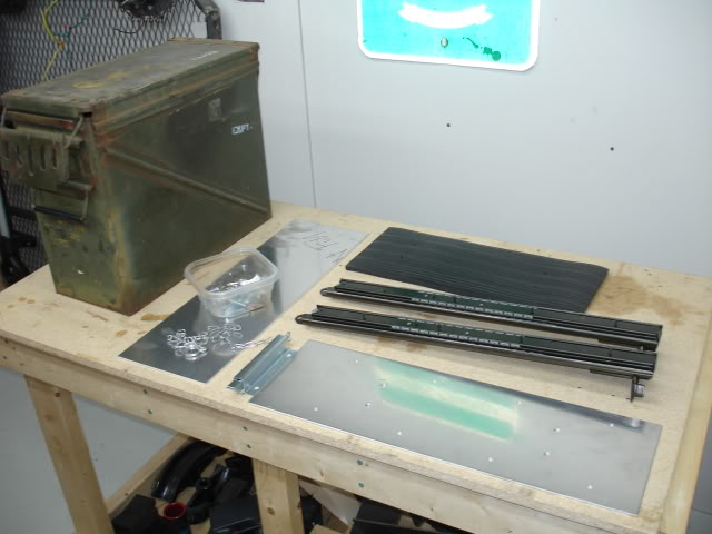
the parts include surplus ammo can, filing cabinet drawer slides, 2 aluminum mounting plates, nuts, bolts, machine screws, magnet, fence latch assembly, loctite, Duplicolor battleship gray paint, primer, workshop foam floor mat, scrap steel.
I was going to simply bolt the ammo can directly to the truck bed, but..... I had to take it to the next level.
The ammo can will hold tools, recovery gear, tire repair kit, roof rack straps and some other junk. I used a plastic tool box for all that gear but the plastic box was cracking. The reason I put the ammo box on slides was.... I hate climbing into the back of the truck to retrieve items I use on a regular basis like roof rack straps this will save my back.
Here's a sequence of the build....
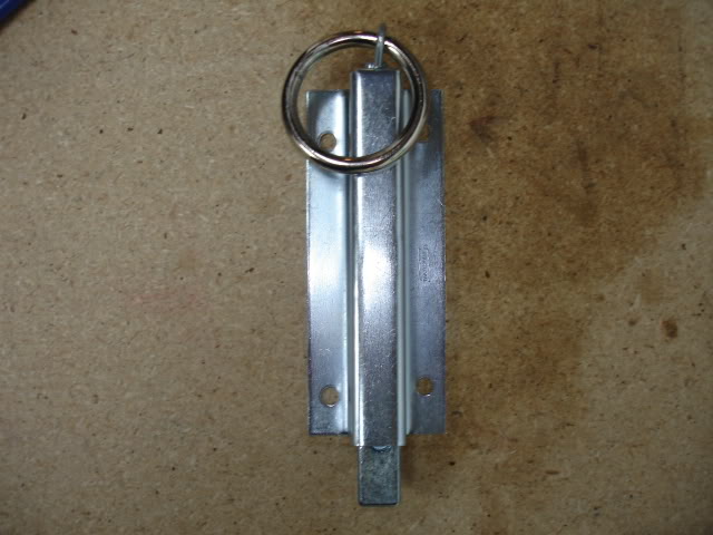
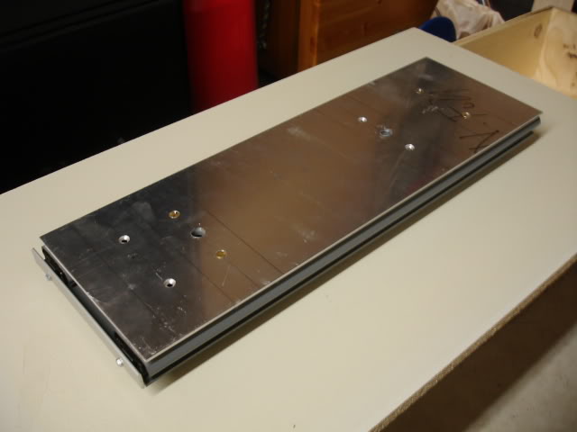
The parts:
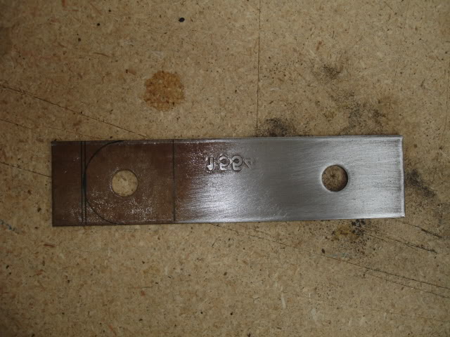
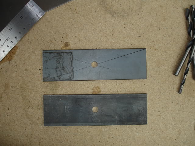
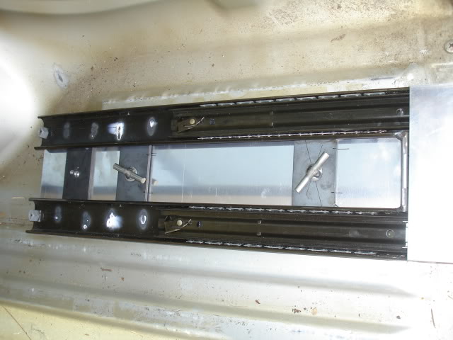
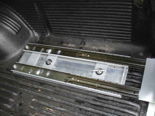
The slides need modification:
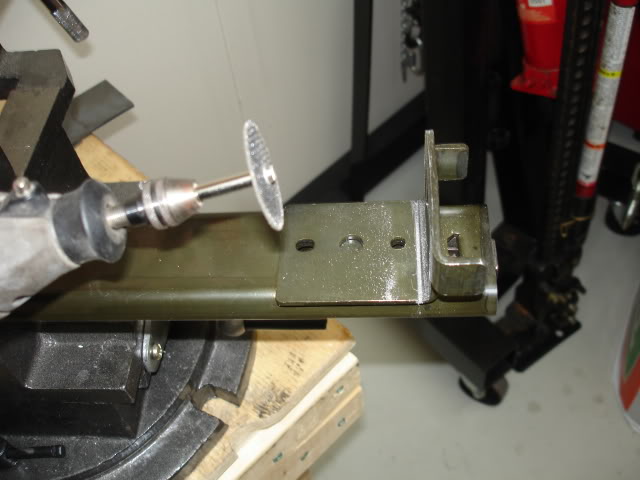
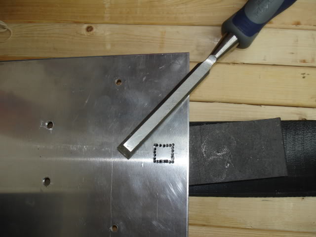
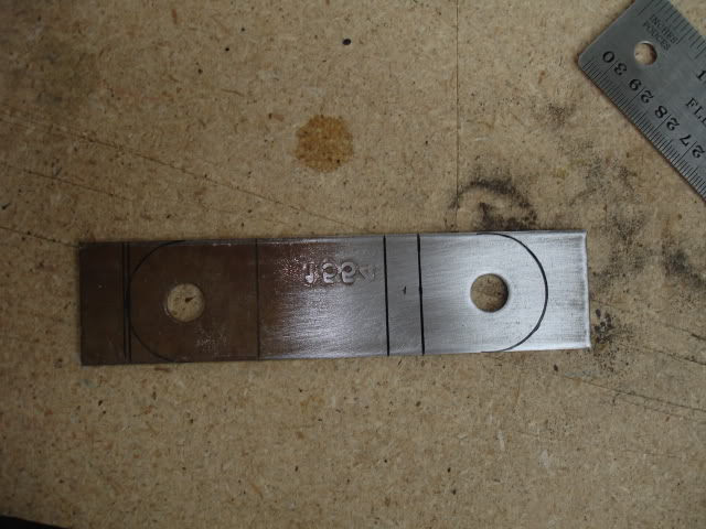
After drilling the holes on the top plate of the slide, I positioned the fence latch in position to figure out how it will work:
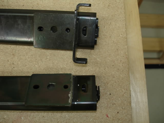
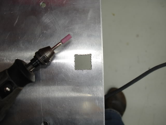
After I was confident the latch position was in the correct place, I drilled perforation holes for the latch hole. I used a chisel to punch out the square hole. The edge of the square hole was cleaned up with the chisel. Aluminum is soft. the chisel worked well and was still sharp after taking the aluminum out:
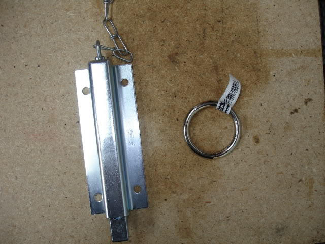
The fence latch assembly came with a chain. I swapped out the chain for a steel ring. Later I added a magnet to keep the ring from banging around. The magnet works really well. I used super glue to secure the magnet. The ring will always return to the "home position".
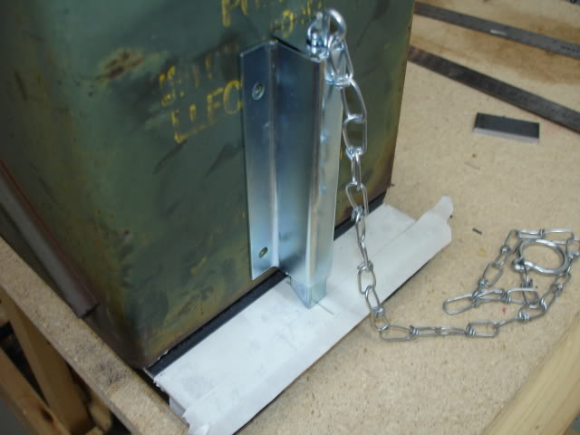
Next, I did a dry fit to make sure I'm on the right track and possibly re-engineer problem spots.
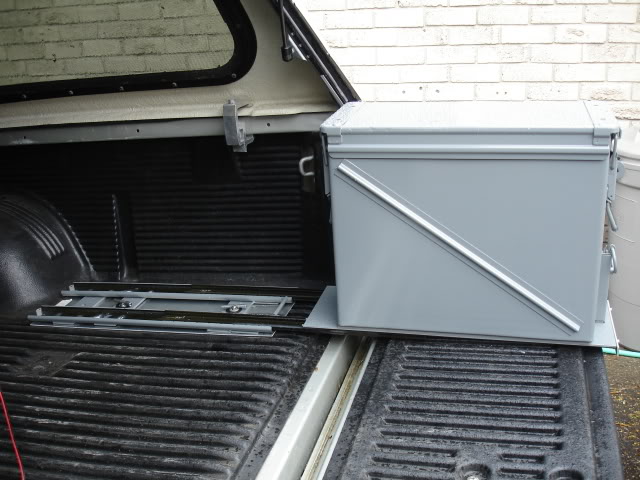
The ammo can in the closed and open position:
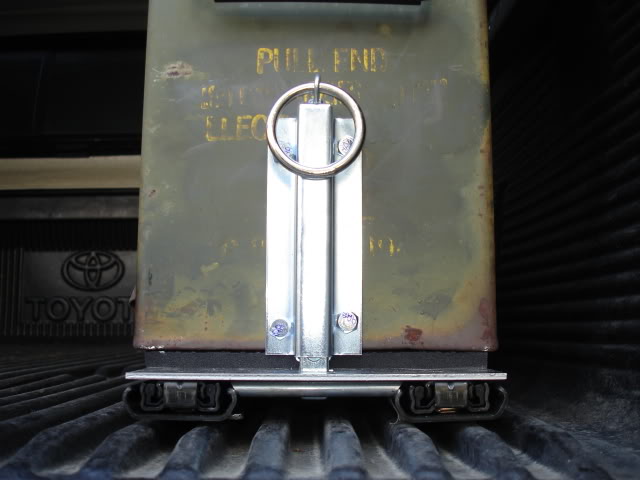
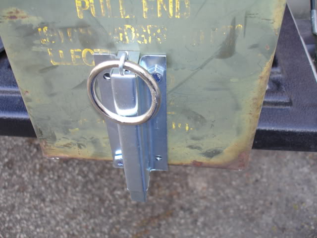
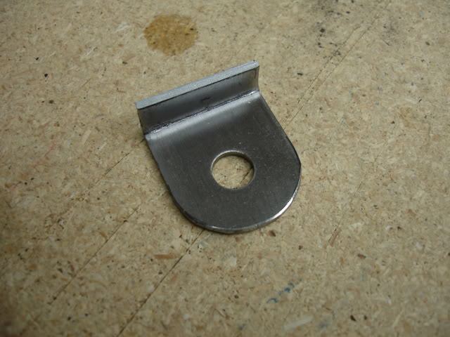
I made a lock bracket for the ammo can:
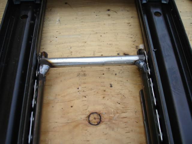
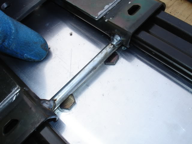
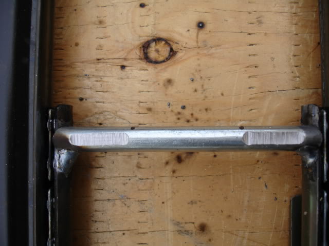
I made some cross members for the slide and welded them into position:
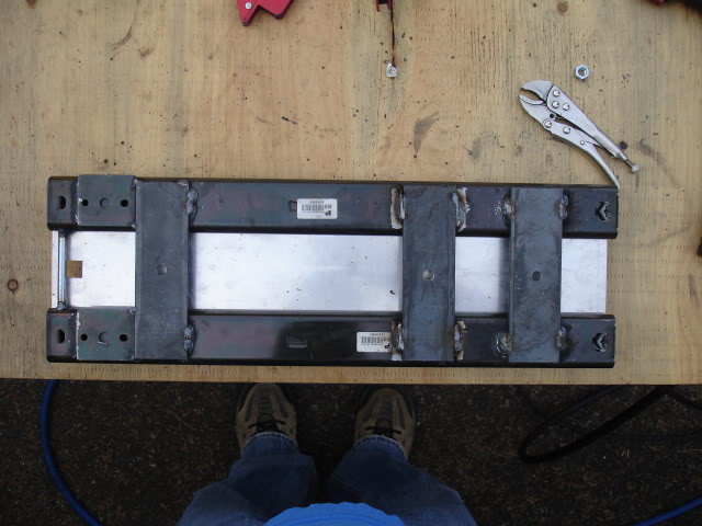
I added the latch lock bar. I had issues with the bolts mounted to the top plate clearing the latch bar, so I did a little grinding:
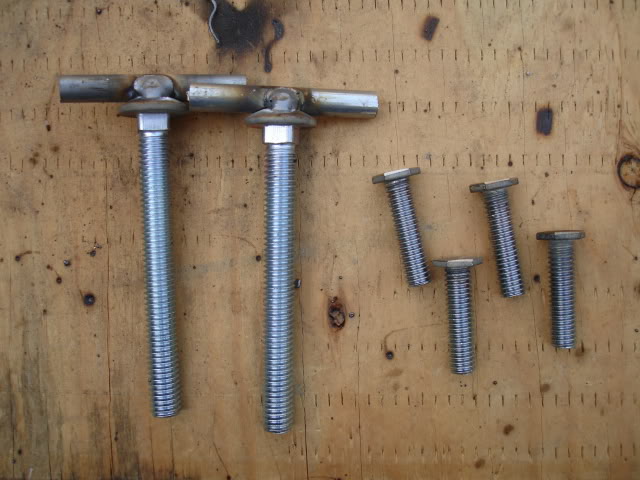
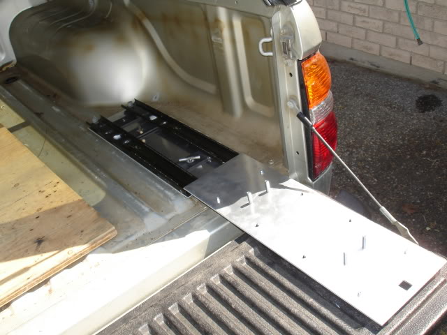
I made some wing bolts for mounting the slide to the bed of the truck. The wing bolts are nice. I don't need tools too take the ammo box and slide out of the bed if I need extra room. The bolts were later cut to correct length.
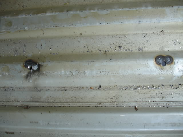
After taking the bed liner out, I drilled holes through the truck bed and welded nuts too the underside. I sprayed some leftover bed liner spray to the nuts and weld to keep them from rusting. The heat marks and damaged paint inside the bed were covered up with some leftover silver automotive spray paint.
Later I put the bed liner back in the bed.
Before bed liner went in, I made sure the slide fit with the bolts in place:
I took apart and painted everything bling Battleship Gray.
I reassembled everything, used Loctite on all the nuts and bolts, replaced some nuts with lock nuts.
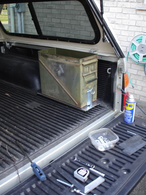
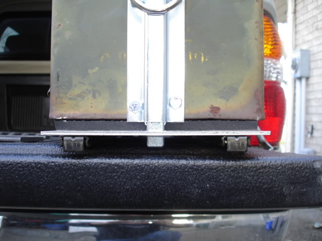
The second pic shows the workshop floor mat, (no I didn't paint the foam mat gray). The foam mat is a spacer/ vibration dampener.
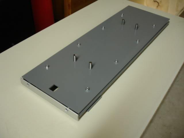
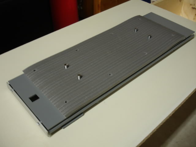
The only thing I didn't paint was the bottom aluminum plate, I may swap it out for a wider plate later...... I have another idea possible add on.
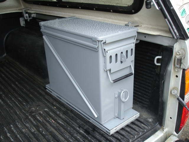
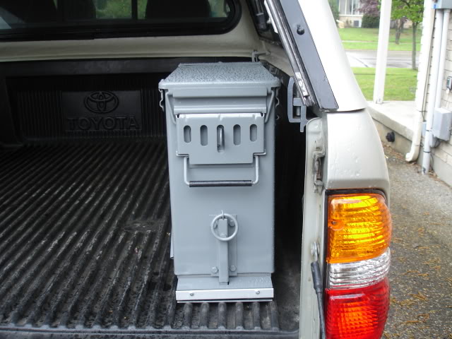
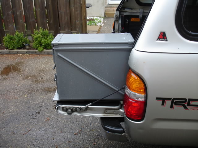
Here's the finished product.
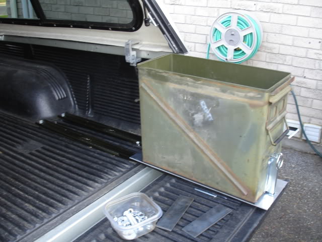
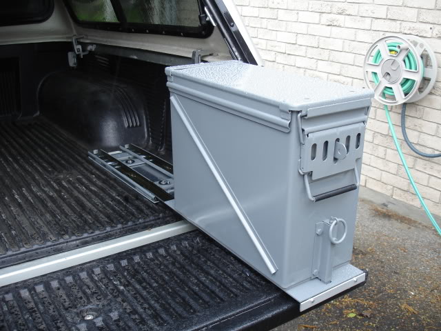
In round of pics the ammo can was loaded with 40 lbs of truck stuff. (yes, I actually weighed the stuff). At 40 lbs @ full extension the slide rests on the tailgate. I designed it to rest on the gate. The slide isn't supporting suspended weight just resting weight supported by the tail gate.
Filing cabinet slides are typically mounted sideways it's designed that way to support fully extended, suspended weight.
I mounted mine flat. I wanted to keep the slides tucked under the ammo can to save weight and keep it nice and tidy and narrow. At full extension the slide drops slightly but does not effect the slide , its very strong and stable. To slide the ammo can back in you lift it slightly and the slide moves fine with full weight. Works better than I thought it would. The slide only drops at full extension when it passes the edge of the tail gate, I may add a piece of plastic to the molded bed liner on the tailgate edge if it becomes a problem. I think it will be fine the way it is, time will tell.
Here are a couple cheap videos:
The vid is posted by weldergirl I hijacked my wife' s account.
http://www.youtube.com/watch?v=CwWpdXgaJWw
http://www.youtube.com/watch?v=NOoFn...eature=related
(May /08) I hit a local mud hole and corrugated dirt roads today and gave the truck a good rattling, shake things up a bit. Every thing is rock solid and the bed bolts never backed off.
I'm taking a trip up north this weekend, its a good chance to further test it.
UPDATE: It's been half a year since the project was completed, I'm happy to say, the drawer slide is holding up strong. The occasional cleaning of the tracks is nesessary, remove the old grease with a rag and replace with new grease. The ammo can has been carrying the same weight and contents since the build was completed, there are some new dents and scrapes but over all the paint has been holding up better than expected.
I have all the parts to build a second Ammo Can Drawer slide.
This was posted a while back in the fabrication section at TTORA.
The idea came to me while sitting on the thrown... go figure.
The project was less than $70 including the ammo can.
the parts include surplus ammo can, filing cabinet drawer slides, 2 aluminum mounting plates, nuts, bolts, machine screws, magnet, fence latch assembly, loctite, Duplicolor battleship gray paint, primer, workshop foam floor mat, scrap steel.
I was going to simply bolt the ammo can directly to the truck bed, but..... I had to take it to the next level.
The ammo can will hold tools, recovery gear, tire repair kit, roof rack straps and some other junk. I used a plastic tool box for all that gear but the plastic box was cracking. The reason I put the ammo box on slides was.... I hate climbing into the back of the truck to retrieve items I use on a regular basis like roof rack straps this will save my back.
Here's a sequence of the build....
The parts:
The slides need modification:
After drilling the holes on the top plate of the slide, I positioned the fence latch in position to figure out how it will work:
After I was confident the latch position was in the correct place, I drilled perforation holes for the latch hole. I used a chisel to punch out the square hole. The edge of the square hole was cleaned up with the chisel. Aluminum is soft. the chisel worked well and was still sharp after taking the aluminum out:
The fence latch assembly came with a chain. I swapped out the chain for a steel ring. Later I added a magnet to keep the ring from banging around. The magnet works really well. I used super glue to secure the magnet. The ring will always return to the "home position".
Next, I did a dry fit to make sure I'm on the right track and possibly re-engineer problem spots.
The ammo can in the closed and open position:
I made a lock bracket for the ammo can:
I made some cross members for the slide and welded them into position:
I added the latch lock bar. I had issues with the bolts mounted to the top plate clearing the latch bar, so I did a little grinding:
I made some wing bolts for mounting the slide to the bed of the truck. The wing bolts are nice. I don't need tools too take the ammo box and slide out of the bed if I need extra room. The bolts were later cut to correct length.
After taking the bed liner out, I drilled holes through the truck bed and welded nuts too the underside. I sprayed some leftover bed liner spray to the nuts and weld to keep them from rusting. The heat marks and damaged paint inside the bed were covered up with some leftover silver automotive spray paint.
Later I put the bed liner back in the bed.
Before bed liner went in, I made sure the slide fit with the bolts in place:
I took apart and painted everything bling Battleship Gray.
I reassembled everything, used Loctite on all the nuts and bolts, replaced some nuts with lock nuts.
The second pic shows the workshop floor mat, (no I didn't paint the foam mat gray). The foam mat is a spacer/ vibration dampener.
The only thing I didn't paint was the bottom aluminum plate, I may swap it out for a wider plate later...... I have another idea possible add on.
Here's the finished product.
In round of pics the ammo can was loaded with 40 lbs of truck stuff. (yes, I actually weighed the stuff). At 40 lbs @ full extension the slide rests on the tailgate. I designed it to rest on the gate. The slide isn't supporting suspended weight just resting weight supported by the tail gate.
Filing cabinet slides are typically mounted sideways it's designed that way to support fully extended, suspended weight.
I mounted mine flat. I wanted to keep the slides tucked under the ammo can to save weight and keep it nice and tidy and narrow. At full extension the slide drops slightly but does not effect the slide , its very strong and stable. To slide the ammo can back in you lift it slightly and the slide moves fine with full weight. Works better than I thought it would. The slide only drops at full extension when it passes the edge of the tail gate, I may add a piece of plastic to the molded bed liner on the tailgate edge if it becomes a problem. I think it will be fine the way it is, time will tell.
Here are a couple cheap videos:
The vid is posted by weldergirl I hijacked my wife' s account.
http://www.youtube.com/watch?v=CwWpdXgaJWw
http://www.youtube.com/watch?v=NOoFn...eature=related
(May /08) I hit a local mud hole and corrugated dirt roads today and gave the truck a good rattling, shake things up a bit. Every thing is rock solid and the bed bolts never backed off.
I'm taking a trip up north this weekend, its a good chance to further test it.
UPDATE: It's been half a year since the project was completed, I'm happy to say, the drawer slide is holding up strong. The occasional cleaning of the tracks is nesessary, remove the old grease with a rag and replace with new grease. The ammo can has been carrying the same weight and contents since the build was completed, there are some new dents and scrapes but over all the paint has been holding up better than expected.
I have all the parts to build a second Ammo Can Drawer slide.
11-16-2008, 06:47 PM
#3
Registered User
Thread Starter
Join Date: Nov 2008
Location: Ontario
Posts: 89
Likes: 0
Received 0 Likes
on
0 Posts
Rear Bumper Build.... Epic Thread!
Alright. I might as well post my rear bumper build.
I'm posting the process, step by step possibly creating one of the longest single post threads. It might help people with their own bumper builds, then again it might not.
I've been working on and off, building this boat anchor for a while, in my spare time, when the weather is nice enough to weld in my driveway. Lately, I've had time to work on it, thanks to our global economic fun-fest. Gee thanks boss!
Right now I'm trying to finish the main part of the bumper before the snow flies. The weather will beat me too the punch, but what can you do?
I need a garage. In the mean time, I make due.
The main reason for the bumper build is... for the sake of building. It's fun! Maybe not for the neighbors, but hell you only live once. I'm sure they'll get over it.
I'm sure the they cringe every time I whip out that grinder.
Mooo ha ha ha...
I'm handing out ear plugs to the parents for Halloween.
So far my fabricating addiction and my love of noise hasn't been a issue with the neigbours, their pretty cool.
I want some beefy "ass" protection! The OEM bumper held up like a champ taking on 4 rear end fender benders, resulting in one minor dent.
The OEM bumper will be my future beer bar in my work shop..... Yippee!
I want something that will scare people into not hitting me... if they do, they're in for some big damage. Other important requirements... tow and recovery points.
I went out of my way to take enough photos to give this thread some "meat", documenting the main steps of the build.
I thought about copying other designs but opted for originality, something different to test my skills.
The design is different but beefy, possibly deflect bullets and give the illusion of stealth technology to thwart radar guns..... I have a vivid imagination. LOL.
The bumper is made primarily of 3/16'' , 1/4'', 3/8" stock - plate and rectangular steel tube.
3/4'' stock was used for the Clevis recovery points, I could have bought them, but thought... " What the hell, I'll fabricate them myself.
I incorporated a trailer hitch box receiver just in case I decide to tow something like a M101 military trailer, if I ever decide to get one...
Possible future build.
I plan on cutting the rear quarter panel for high clearance. The bumper will accommodate side panel, detachable, high clearance square tube protection, yet to be designed and built. The side protection attaching points have been incorporated into the corners of the bumper..... you'll see.
I'm also adding brackets for rock lights on the inside of the bumper.
Air lines: female couplers will de added. on either side and rear of the bumper, for tire inflation and the air mattress for our tent. I thought about turning the bumper into a air tank for use on the trail, but a tankless, good air compressor will do just fine, I'm not in a race.
The bumper and side protection will be strong enough to use a Hi-Lift jack.
A swing out tire gate will be designed, steel cut and dry fit this winter in my basement shop, ready for welding in the spring. Unless I come up with another solution for the spare tire.
The bumper will not be installed until spring, I'm not planning on wheeling this winter anyway.
This spring my truck will see real transformation when the pile of parts are finally glued to the truck. I'm in no rush, there are still a few parts I need anyway.
The main tools I used were:
- A frickin loud disk grinder
- die grinder
- Miller 175
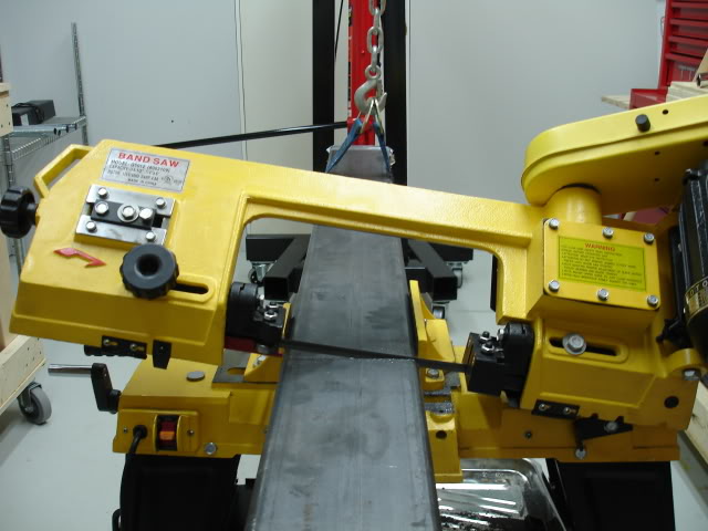
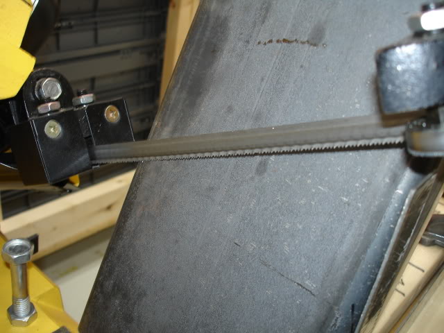
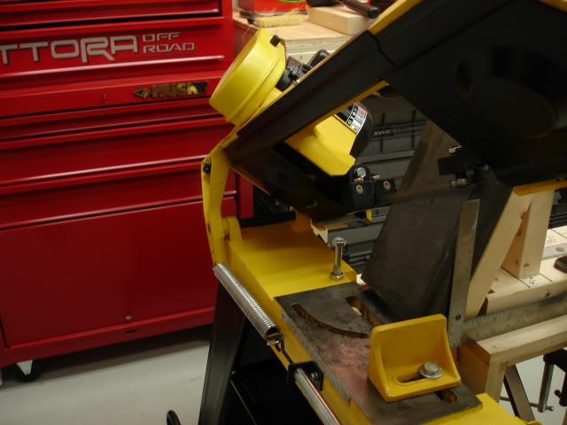
- my trusty band saw (I love that thing!)
- various magnets
- my hands and brain
- ruler, level
- air wrench
- jack stands
- camera
- flat stock bender
- blowtorch
- drill press
- jig saw
- Beer
- belt / table grinder.... and a few other tools, I can't think of right now.
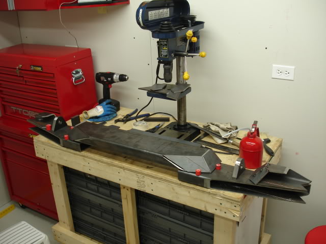
Well enough jibber Jabber, heres the build.....
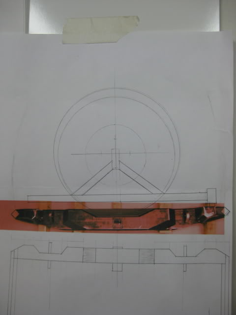
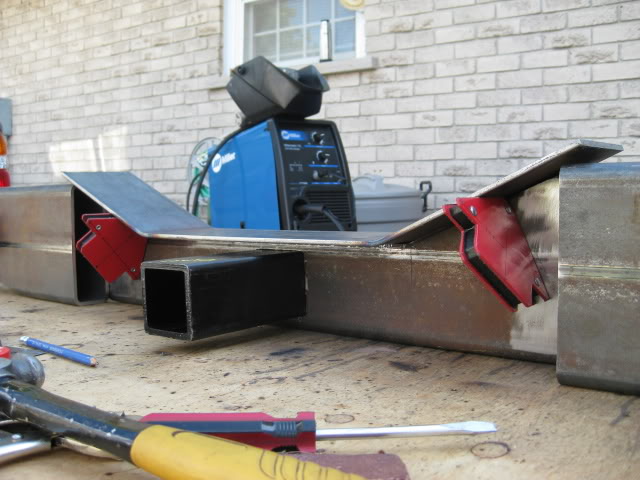
First thing I did after making some sketches and taking measurements and buying stock, is cut the rectangle tube stock into the lengths and angles needed.....
I'm not including the pics of my drawings, they were destroyed by a beer explosion. I'll build up the drama by posting sequence pics. LOL...
Next I cut the box tube for the driver and passenger side higher clearance profile....
Clevis recovery points...... The next thing on the agenda.
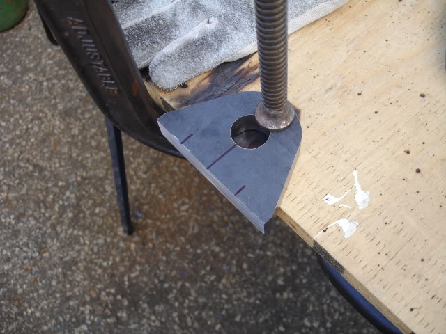
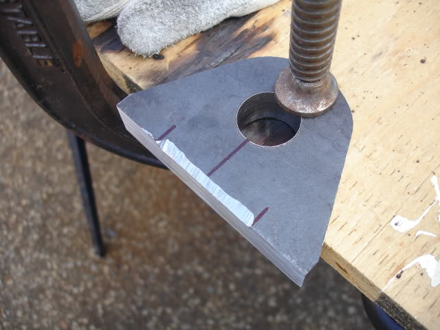
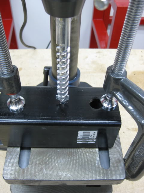
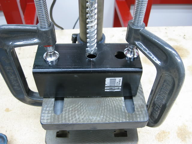
I used 3/4'' steel blocks. This build was a complete experiment, largely due to the fact, I was using a Master Craft hobby bench-top drill press and 1'' Bi-Metal hole saw. LOL...... Lets just say I put this machine to the test and then some.
I'm very impressed with this drill press. I will be upgrading it eventually, hopefully with a mill drill or milling machine.
The key to drilling thick steel with this drill press is:
- dropping the dill speed as low as possible
- clamp the work so nothing shifts
- drill a small diameter guide hole
- use a lot of cutting lubricant.
I took my time, keeping the heat down, stopping to cool the motor, in the mean time I used a Shop Vac to remove metal shavings.
I didn't force the pressure on the drill press to speed up the cut!
After drilling two hole with the hole saw, the saw was still sharp.
You'll notice I put the drill press in a bucket, with some card board taped too the inside of the bucket. This was my solution to keep the sloppy mess down, making it easier to clean up.
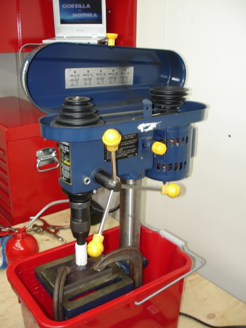
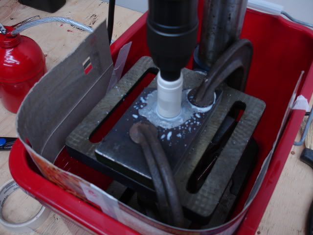
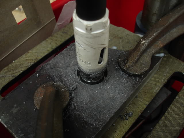
The hole saw cut turned out better than I though.
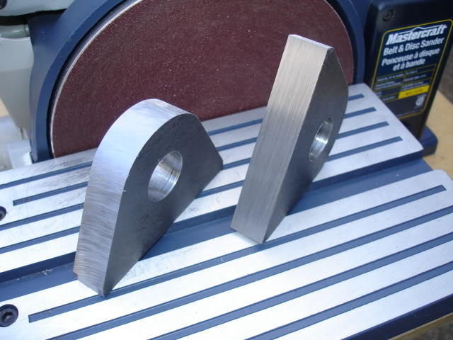
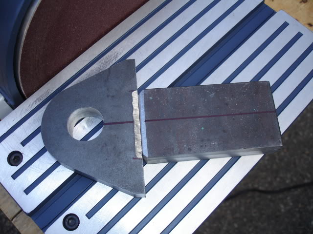
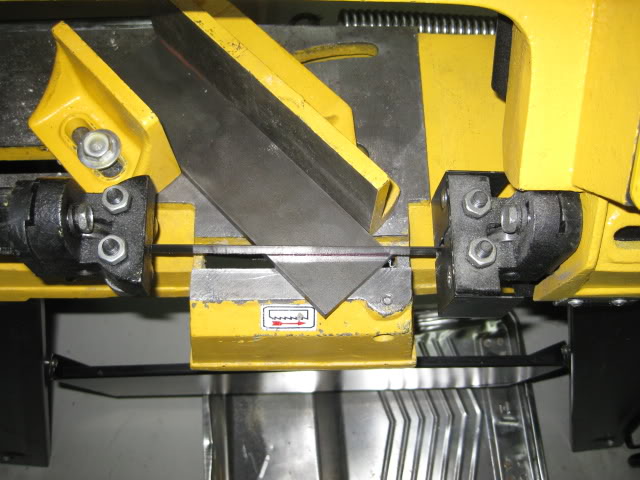
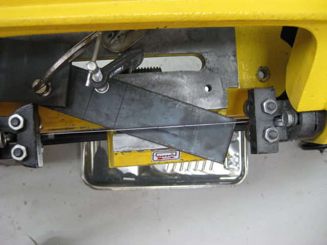
the next step was too cut the 3/4'' stock into the shape of a clevis point....
Back too the band saw... The cuts take a while. While I sat there baby sitting the saw, Godzilla was entertaining me... Godzilla vs. Mothra. Classic!
I love monster movies.
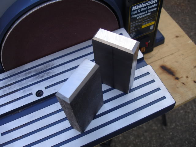
The next step was giving the cut edges of the clevis a smooth finish, for this I used a table disk/ belt grinder.
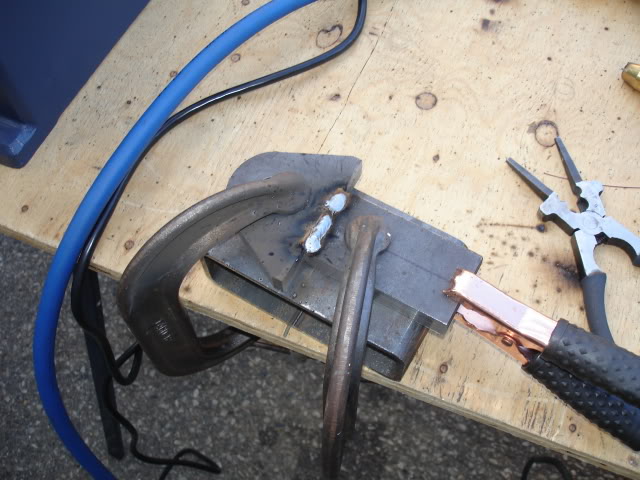
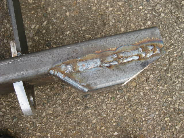
The clevis I designed is meant to go through the bumper, welded on either side, front and back of the bumper, as well as the inside of the boxed section of the bumper. Over kill!
The clevis will be connected to the mounting brackets that attach directly to the frame.
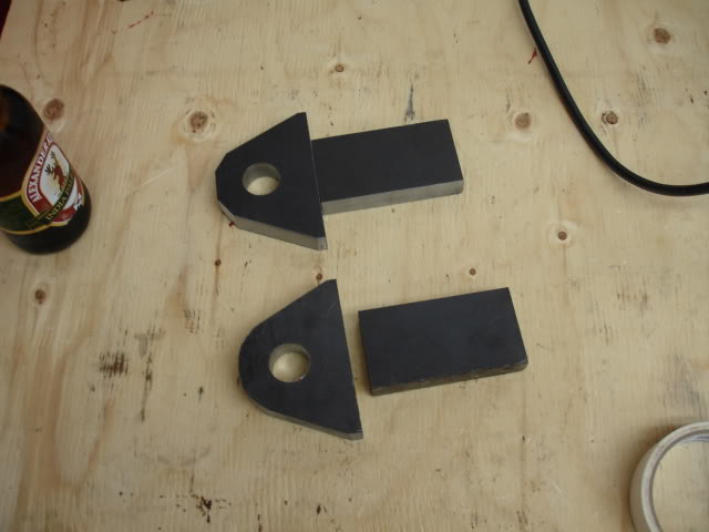
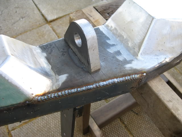
I used two pieces for the clevis points welding them together too make one piece. I beveled the edges of the clevis parts were the weld would be applied. I managed to get pretty good penetration. I put one of the clevis points in a vise and gave it a couple good wacks with a hammer to see if it would crack the weld. All was good so I ground the excess weld down to clean up the surface.
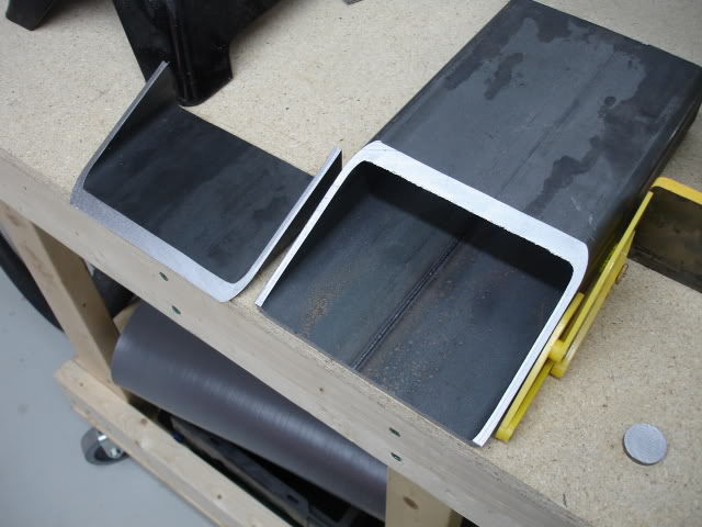
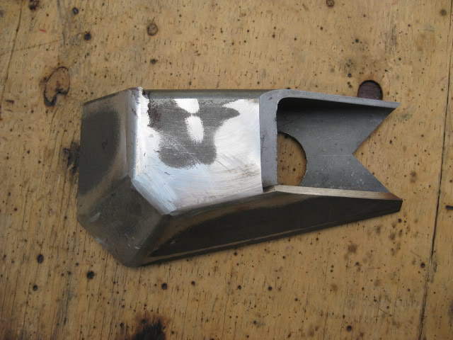
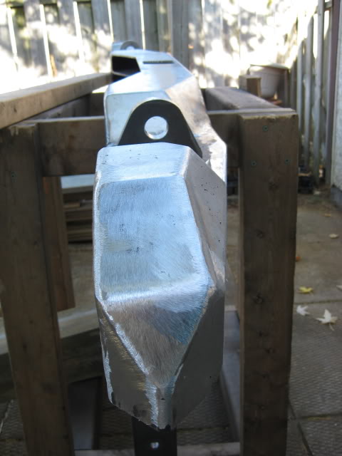
The bumper corners are unique. The main purpose for this is: Too give the bumper some extra beef and depth, more area to" weld in" hinge towers with gussets for the swing out gate, recess the clevis points so they don't stick out too far on the out side surface of the bumper, and.....
To be different.
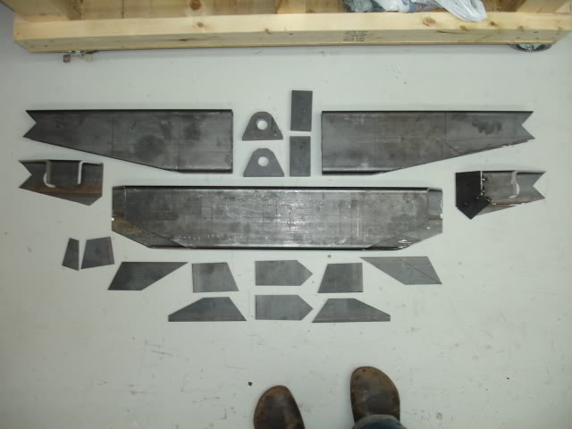
I used the band saw to create the main pieces for the corners.... confused yet?
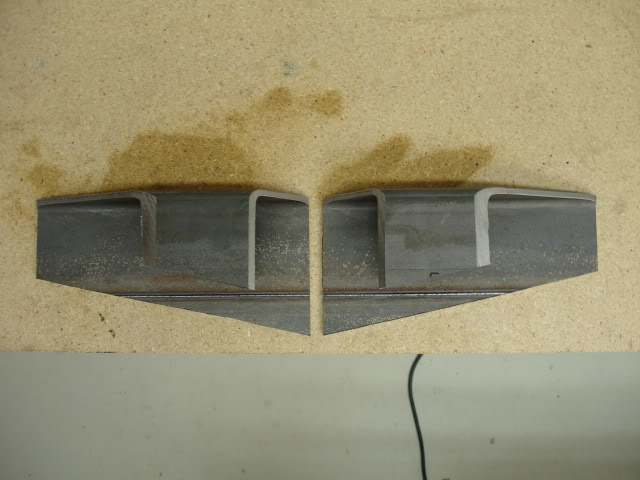
I used card board for the plate templates to get the general shape....
I used 3/16'' plate steel for the angled surfaces....
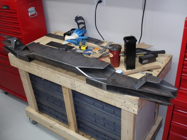
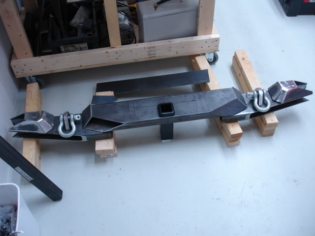
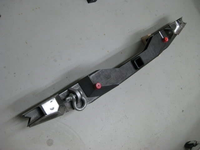
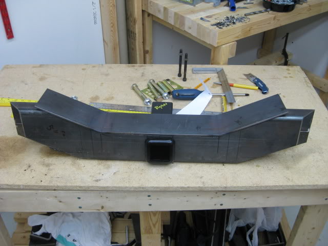
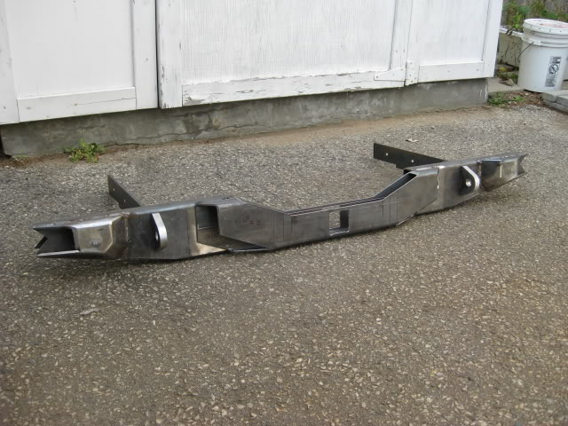
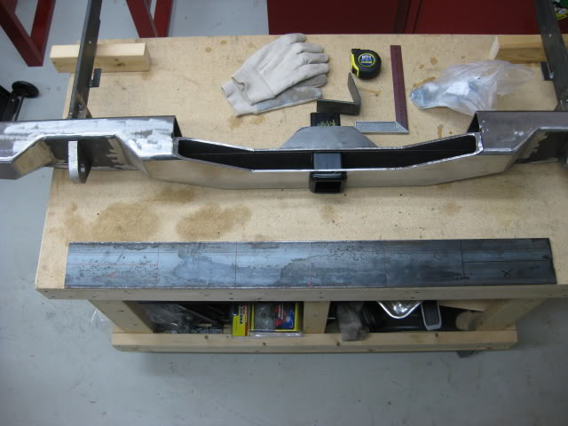
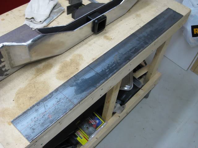
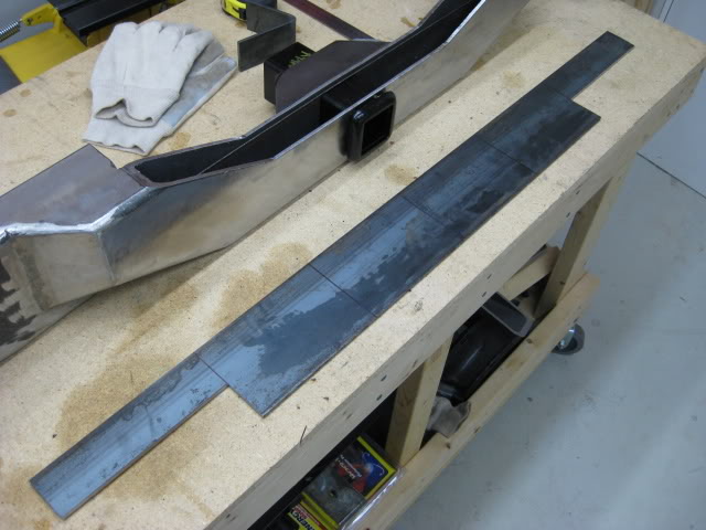
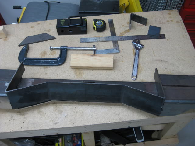
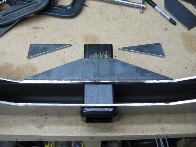
Ok here is the basic layout of the bumper on the work bench....
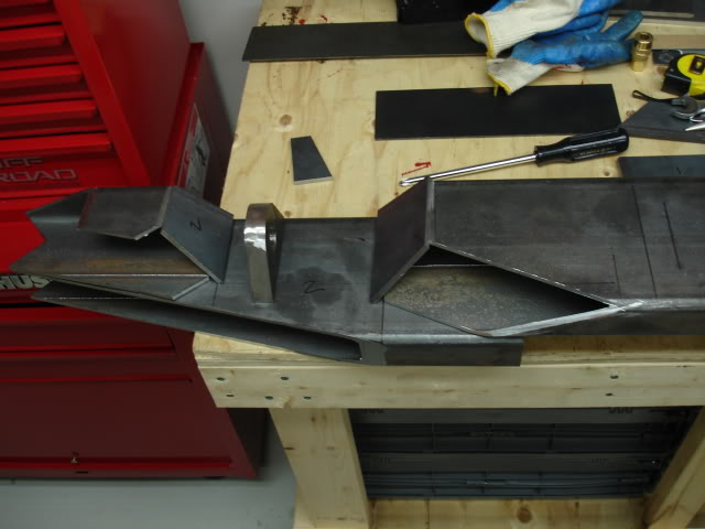
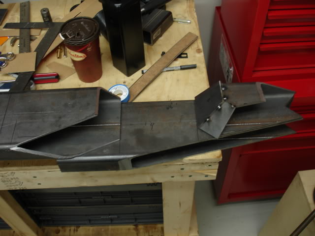
The next pic shows the basic pieces for the main part of the bumper....
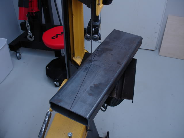
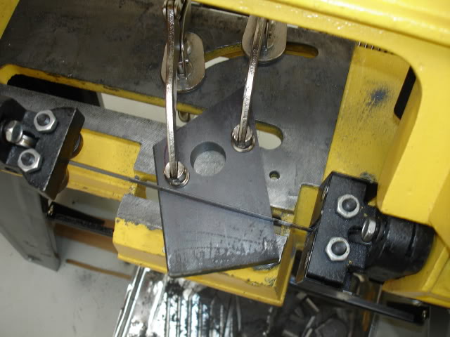
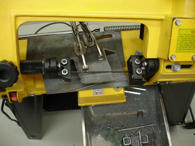
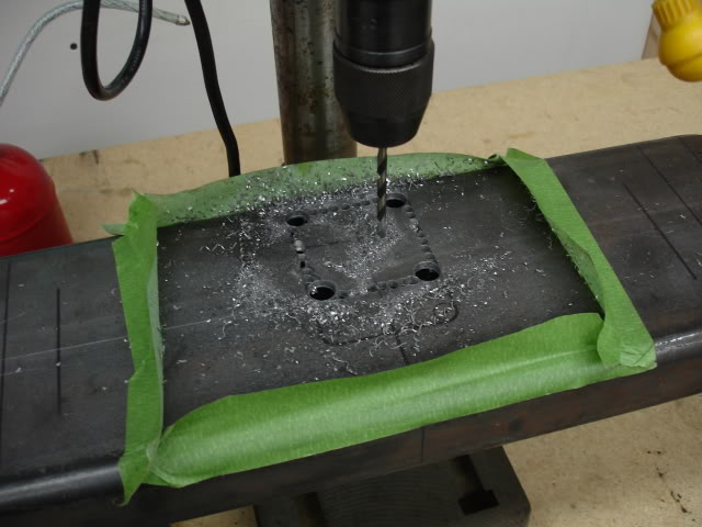
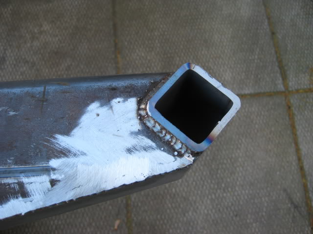
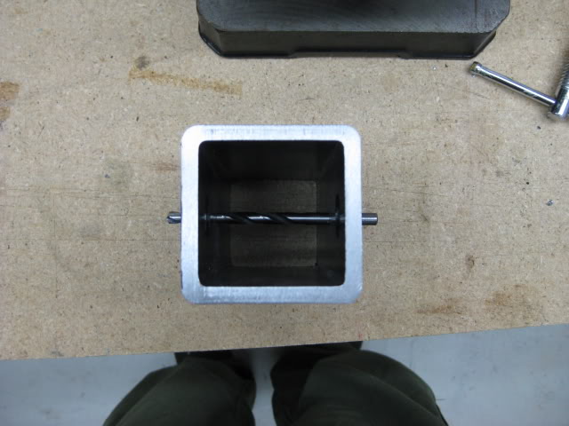
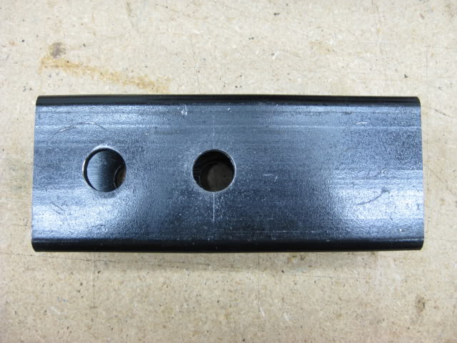
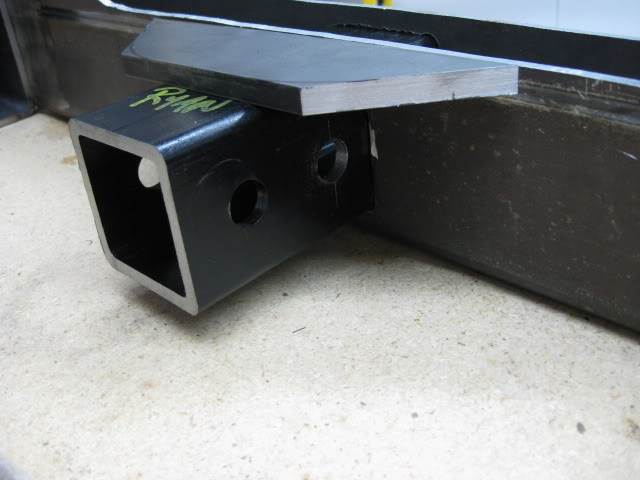
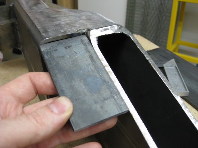
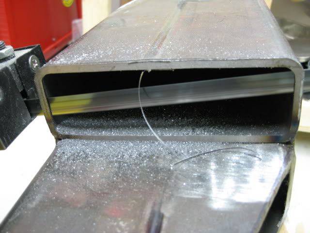
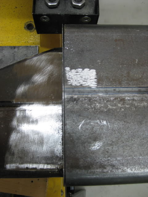
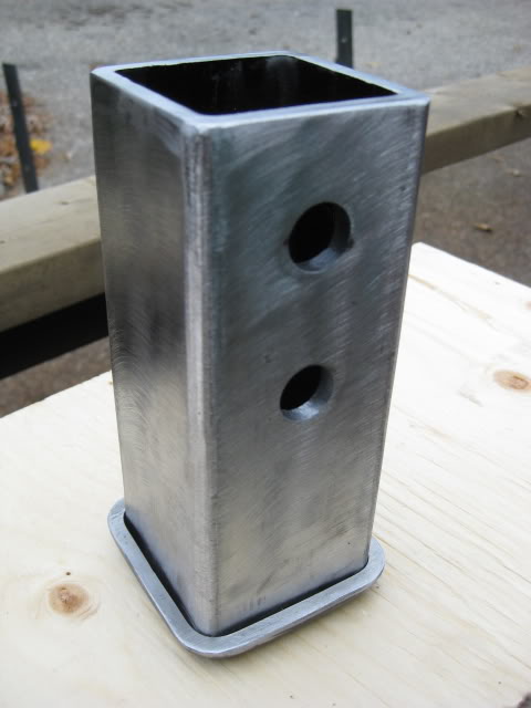
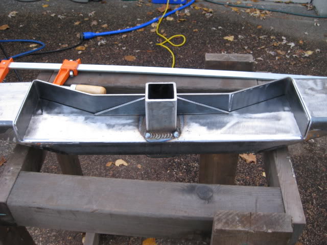
A box trailer hitch receiver is part of the bumper design. I wanted to keep the receiver as high clearance as possible. In order to achieve this I had to cut a 2-5/8'' x 2-5/8'' square hole out of the bumpers mid section to fit the receiver through the bumper.
This step was another challenge. It would be a piece of cake if I had a plasma cutter. I could have called a family member that has a plasma cutter but I like doing things the hard way.
I was up for another challenge and devised a plan.....
Taken from a old-school tool and die technique, I perforate the rectangle box with a drill press. After perforating both sides of the box section, I used a jig saw to cut through the perforations. Worked like a charm! I didn't bother grinding the inside edges flat. I ground just enough to fit the box receiver through the bumper, nice and square.
See! I don't need a stinking plasma cutter!
Ya right! ....I just can't afford one right now.
Unfortunately this is the only pic of this step, you'll be able to see it in later pics.... I think.
Back to the bumper corners.... I welded the angled plates into position and ground the welds, smoothing them out. I also used a hole saw to drill out holes on the backside to lighten up the corners.....
What a time too nickel and dime. If I had a plasma cutter I would have removed more steel.
For the most part the fancy corner thing-a-mabobs do not weigh all that much.
( I'm doing a 63'' rear Chevy leaf spring swap so the weight factor is a not all that bad, although that may change if I decide to mount a spare tire gate, I may have to add a forth leaf, but thats another build.).
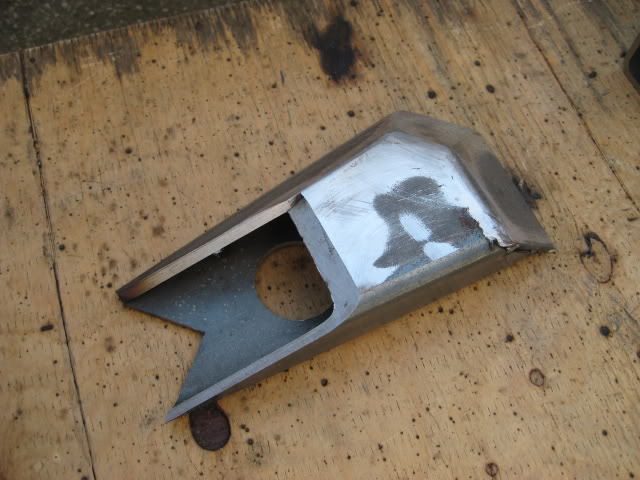
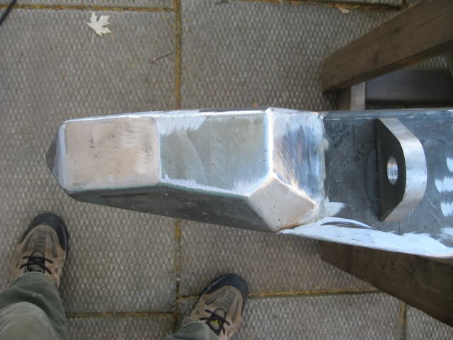
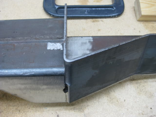
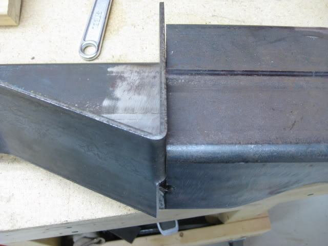
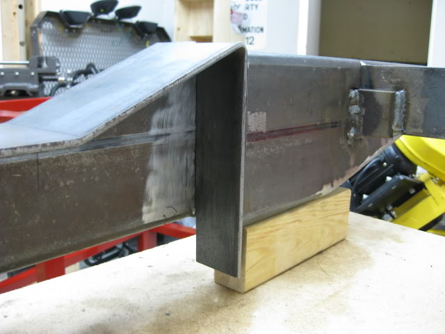
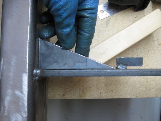
The outside corner edge looks pretty scary!
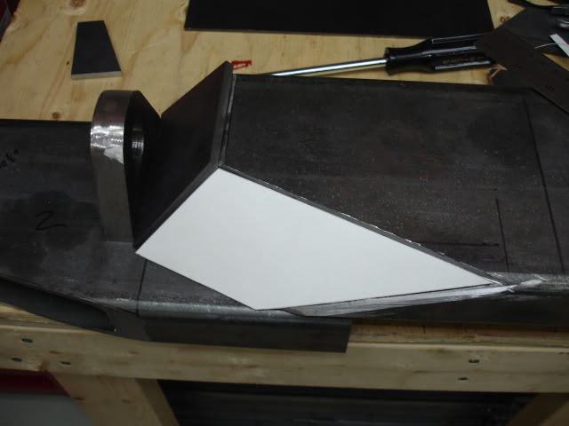
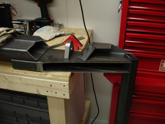
I notched out the corner to accommodate square tube for the side quarter panel protection ( trimming the fender for higher clearance) originally I was going to mount the tube square to the ground, but just to complicate things I decided to clock the tube 45*
The next photo shows what I had in mind regarding the 45*...... Fancy, eh?
During the build I would assemble the parts, take a picture or two and think about what I have, making sure it will still work.
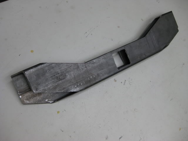
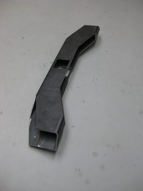
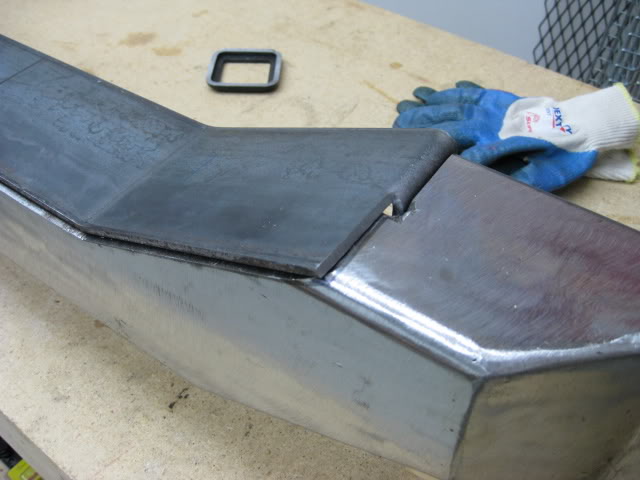
After looking at theses pics, I decided I could lighten up the bumper, a bit, by taking out a section of the center piece above the receiver hitch. this would possibly help lower the height of a spare tire, I won't know until I get to that stage. Another use for the change would be a step. It could be handy for adjusting loads and straps on my roof rack. The step would also transform the bulky look of the mid section.
I'm also using the step plate as part of the gusset for the hitch receiver and re-box the mid section.
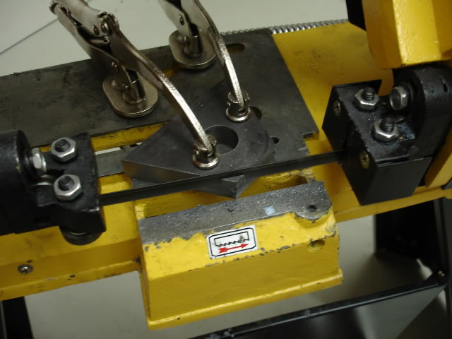
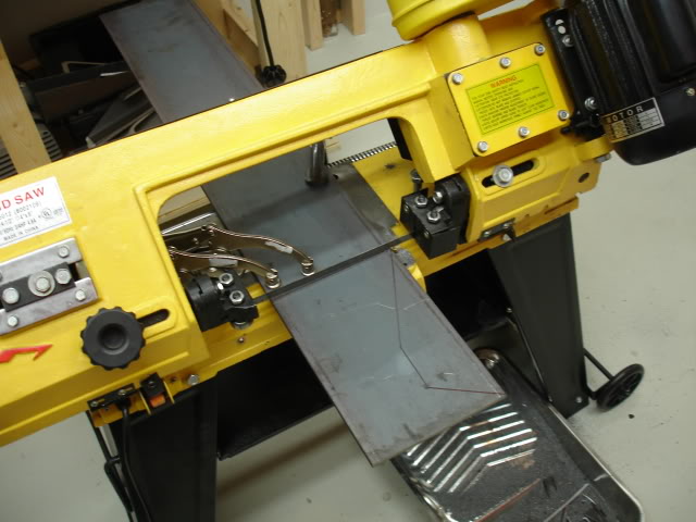
I used my trusty band saw to remove the material to create the step. It was a slow process.
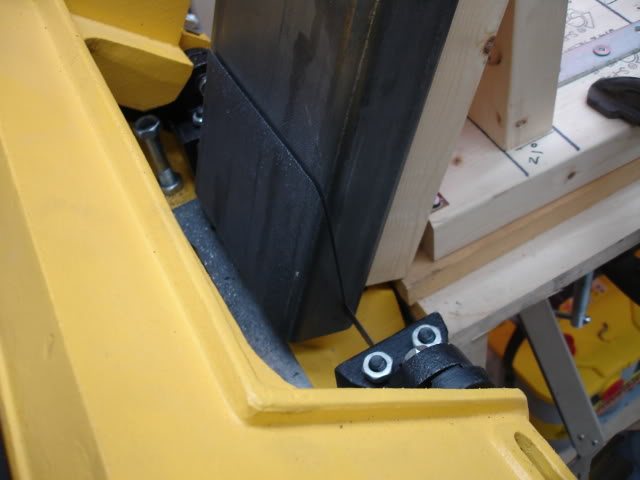
It's amazing what you can do with a band saw. I used the drill press again too drill the corners so I can pivot the band saw blade too cut straight across the box mid section.
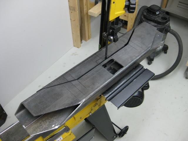
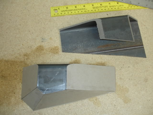
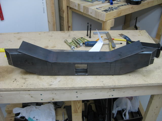
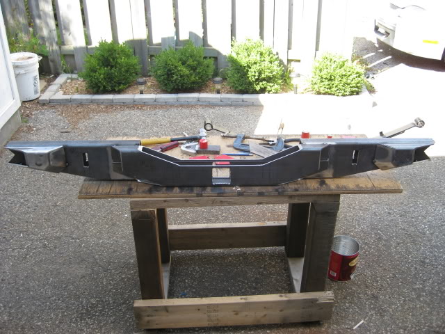
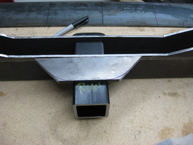
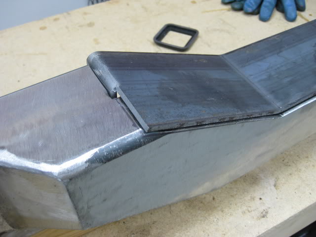
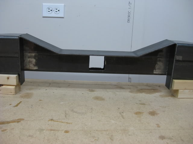
Here's the mid section from different angles....
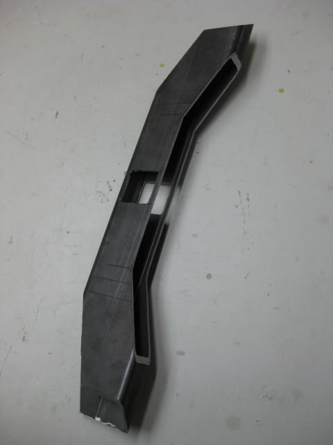
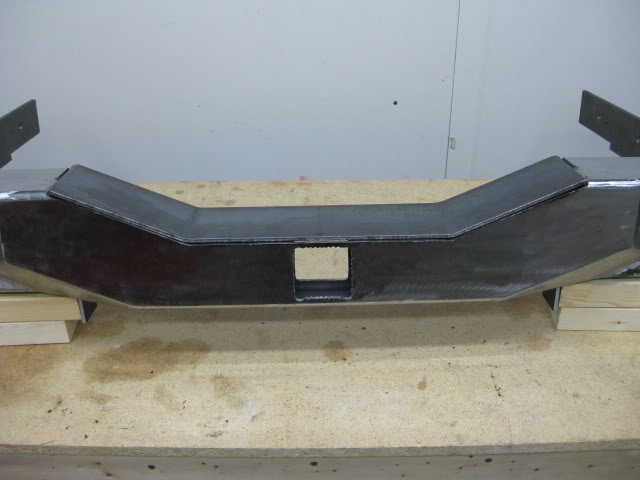
The after pic of the mockup assembly.....
After the mid section step was cut and evaluated over a cold beer. The next step was creating a step plate.
I thought about using diamond plate but after visiting the steel store, my measurements and cardboard template indicated diamond plate would not be the best solution.
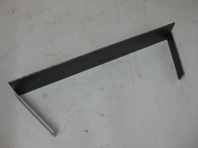
I wanted to use a one piece plate with bends rather than three plates welded together to create the angle.
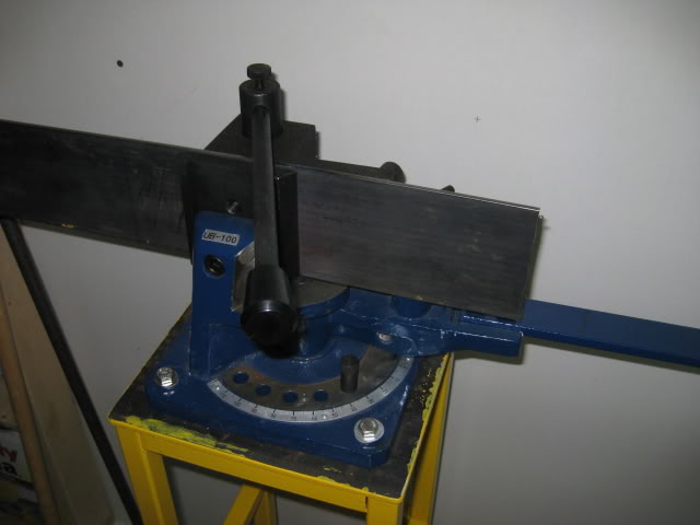
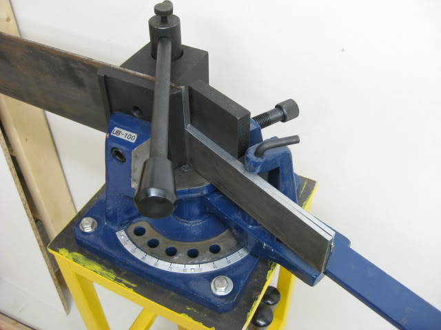
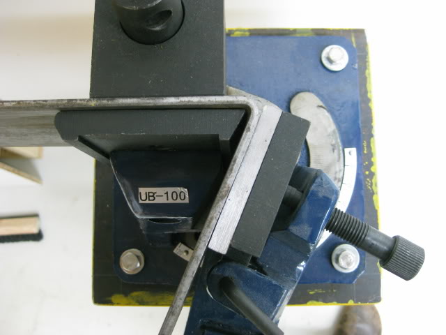
I have a plate and angle iron pedestal bender. (another tool, I love!)
The diamond plate would be hard to bend, the diamond pattern also didn't work well with the measurement I had.
I decided to go with 3/16'' standard flat plate steel.
I can add a anti slip surface later in the build..... Like grip tape, spray on / roll on bead liner, or weld my forum name / signature on the surface of the plate.... the creative juices are flowing again. LOL.
Anyway......
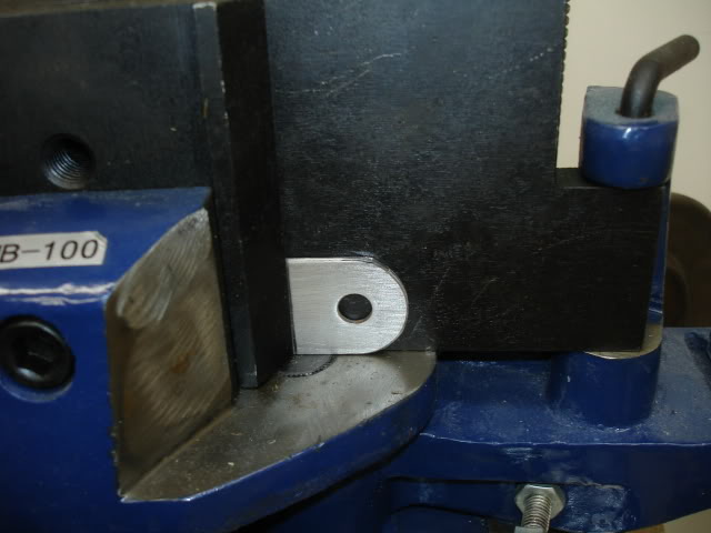
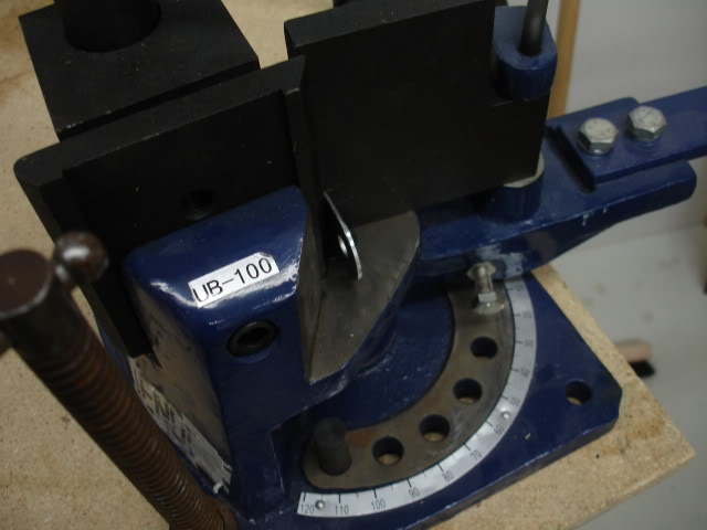
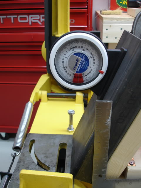
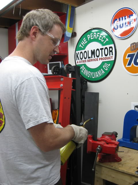
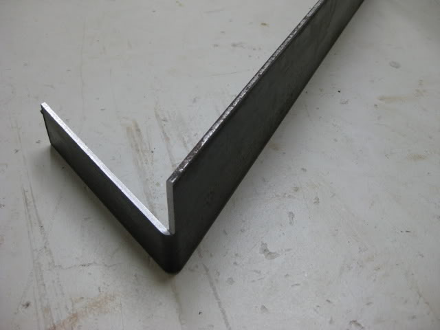
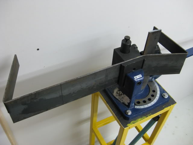
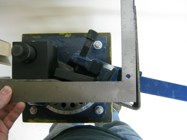
Before I do any bending, I double checked the measurements with the template, cut the plate to a slightly longer length (just in case), mark the plate where the bend will be, Place the plate in a vice and add heat. I used a MSP* gas (methylacetylene propadiene, stabilized.), also known as MAPP gas. I used this gas over propane because it will burn hotter. The hotter the bend location is, the easier it is to bend the steel, creating a sharper bend Some times a radius bend will occurs with cool steel, heat is required with this type of bender.
Here's an ugly of me, the bender and the result......
Tack weld time!
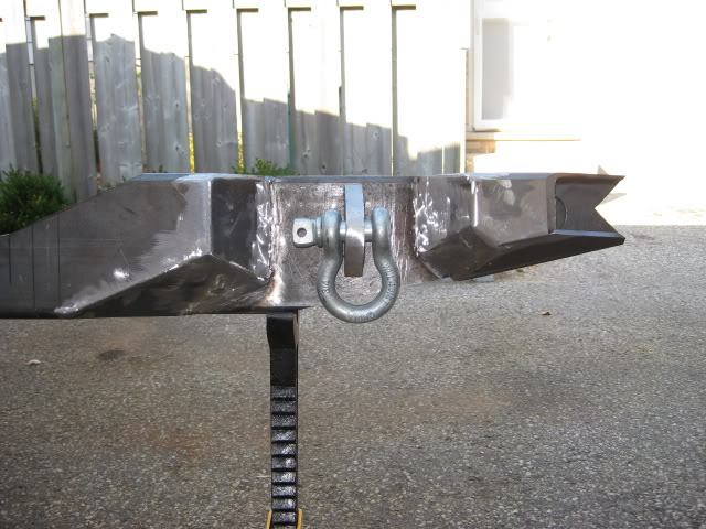
Well, before I get ahead of myself, the Clevis points mount through the bumper, I figure the recovery points will be stronger that way, rather than welding the clevis points to the surface of the boxed section with no material between the recovery point and the frame brackets.
I used the same technique to remove material, as I did for the hitch box receiver... perforation holes with a drill press and cut with a jigsaw.
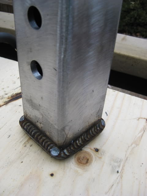
Back to the tack welds. I had the measurements of the outside frame width. Having measurements, I tacked up the bumper so the out side edge of the clevis points match the width if the outside mounting surface of the truck frame.
With the tack welds in place, it gave me a rough idea of how much I would have to tweak the distance between the clevis point to make the new mounting brackets fit the frame. I ended up grinding off the tack welds three times to get the proper distance between mounting brackets.
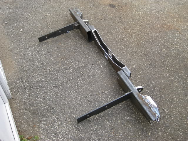
Bumper mounting brackets: I used 3/8'' steel stock.
Before cutting and drilling, I used cardboard as a template to locate the OEM mounting holes on the truck frame and weld locations of the OEM shackle hanger welds.
After cutting and drilling the mounting brackets, I did a dry fit to make sure the bracket holes match the frame holes, I bolted the brackets to the frame and took bracket length measurements so I can cut them to the proper length. Then removed them.
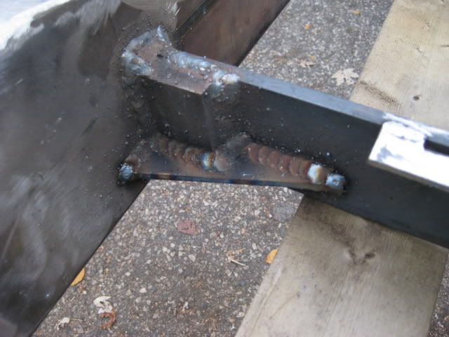
I took the time to fabricate bracket tabs to help support the bumper weight on the inside of the frame, while mounting the bumper, just like the OEM tabs.
The tabs make it easier for one person ( me ) to position the bumper on the frame. I then position jack stands under the main part of the bumper to carry the bulk of the weight while I bolt the bumper to the frame. Its a real back saver.
Next, I tack welded the brackets to the clevis points, them mounted the bumper on the truck. Like I indicated earlier, it took three attempts to get the distance between the brackets right to match the frame width. I managed to get a perfect fit. While I was at it, I welded the top of the corner thing-a-mabobs so I can grind the welds flat to make the bumper top surface look like one piece. Grinding came later.
Its tricky welding outside, the wind tends to blow the shielding gas away, I managed to get some half decent welds. There was a lot of weld applied to fill the gap between the pieces, I then added smaller filler welds to even it out.
Again I took pictures of the bumper, earlier, of the boxed hitch receiver and step plate, in their rough position to get an idea of how they will fit. That way I can sit back in the evenings and think, without wasting the day away dreaming about the solution, with the bumper in front of me. If I had a garage that might be a different story, and I don't feel like lugging that thing down stairs.
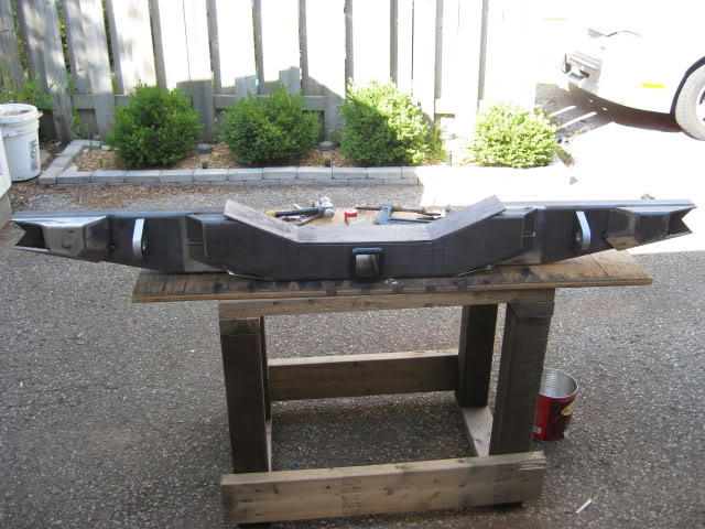
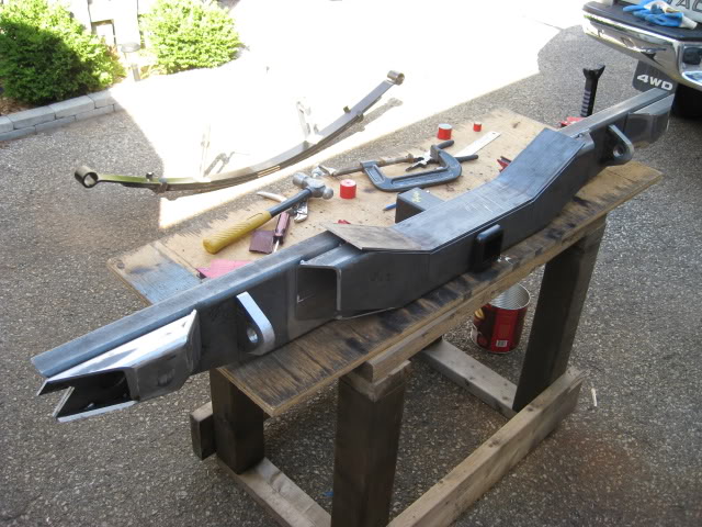
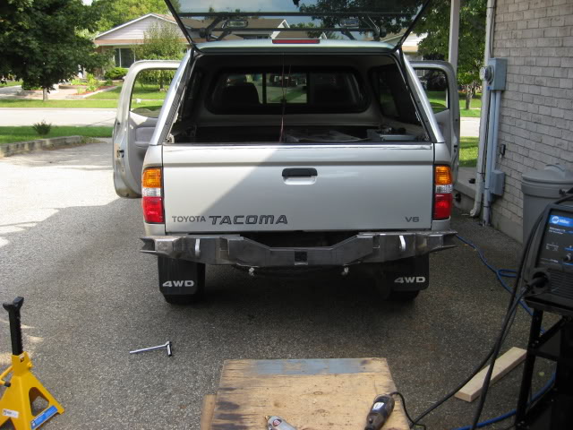
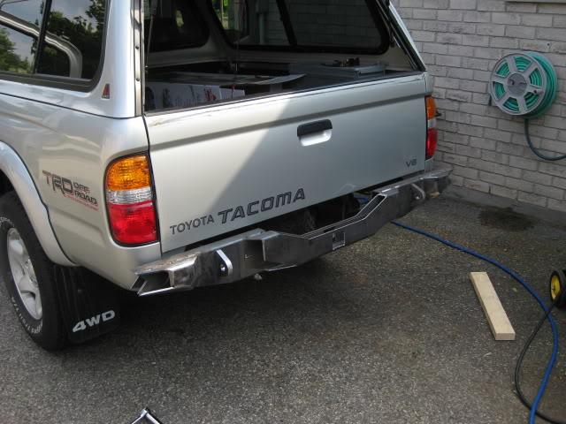
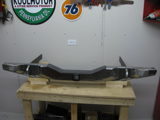
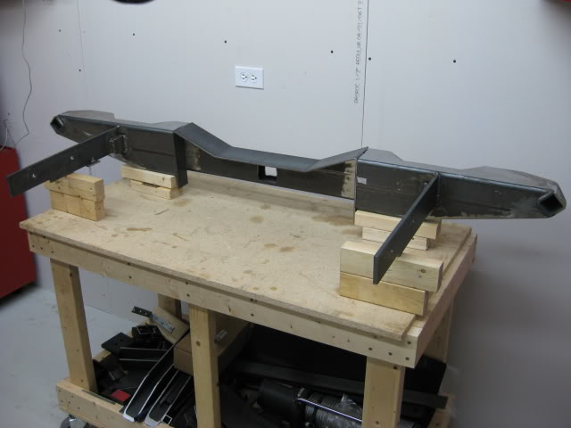
This is the bumper mounted at the tack weld stage. The result was a perfect fit.
Scary corners eh? LOL. It made a few friends scratch their heads. Its a fricken weapon!
Finally it's time to weld the angle plate pieces in place, to box up the bumper and get the bumper shape I was after.
The plate pieces tacked in place. The pieces butt up together create a ''V'' this gave me the opportunity to get deeper weld penetration.
With a deeper weld penetration I could grind the weld too a smooth shape without loosing too much weld integrity. All the plate welds on the front of the bumper were treated this way. I would only grind off enough weld to smooth them out.
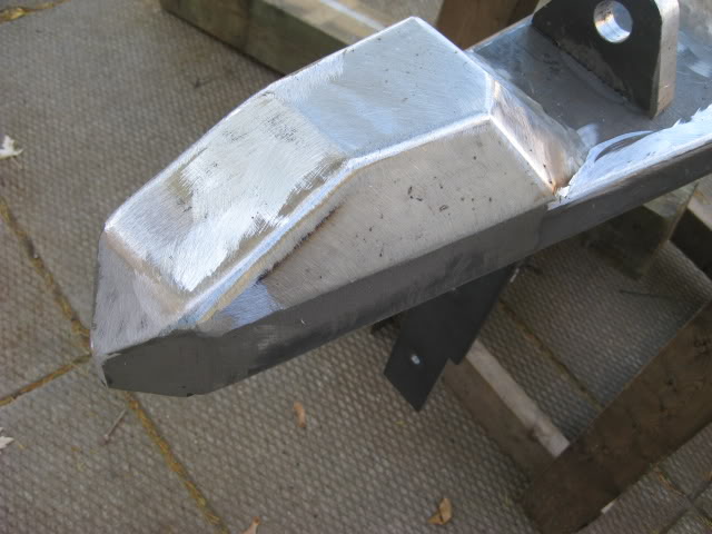
Now, its time to tame the bumper corners, make it less of a weapon.....
Earlier I mentioned I was planning to trim the rear bed quarter panels for higher clearance and add side protection using 2'' square tube. This is still in the design stage. Although I did get a head start.
As mentioned earlier, I was going to mount the square tube, square to the ground, but instead I decided to clock the tube 45*, just too be different....
I was going to "weld in" full length tube to meet the edge of the wheel well, but decided to make the side protection detachable. This would make the bumper easier to man handle during the install, and removable incase I need to replace or change side protection, or just leave the bumpity bump the way it is without side protection. I like having these options. I have all winter to think about it.
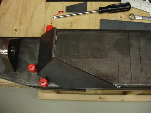
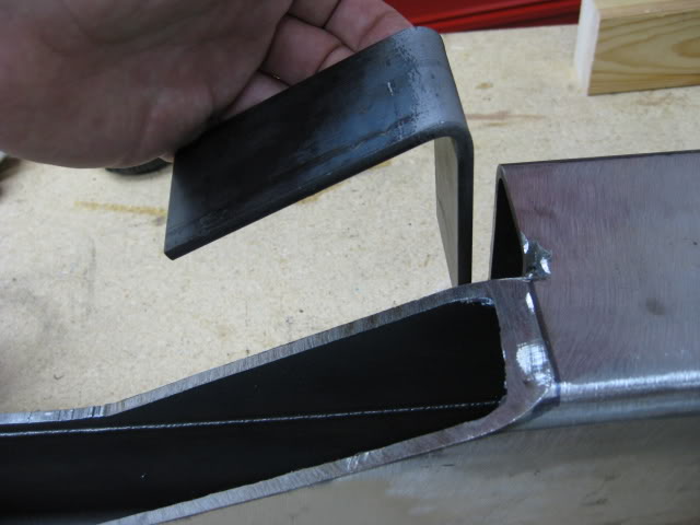
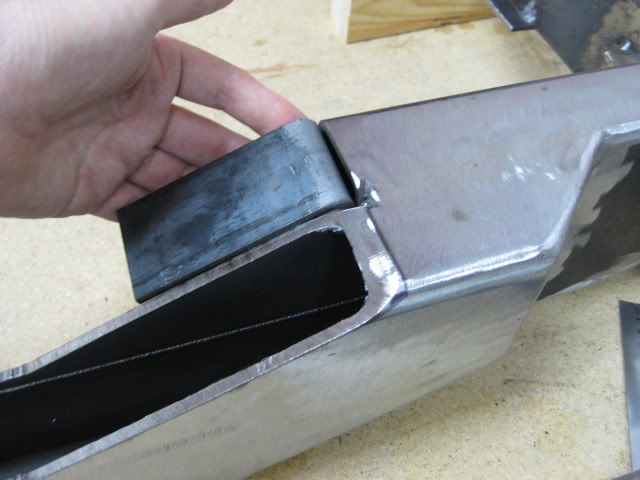
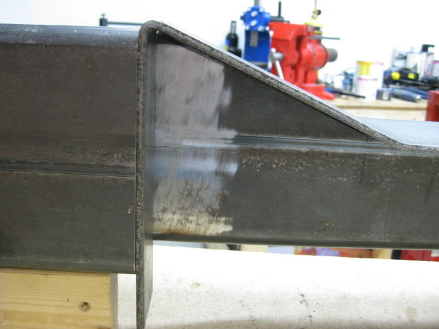
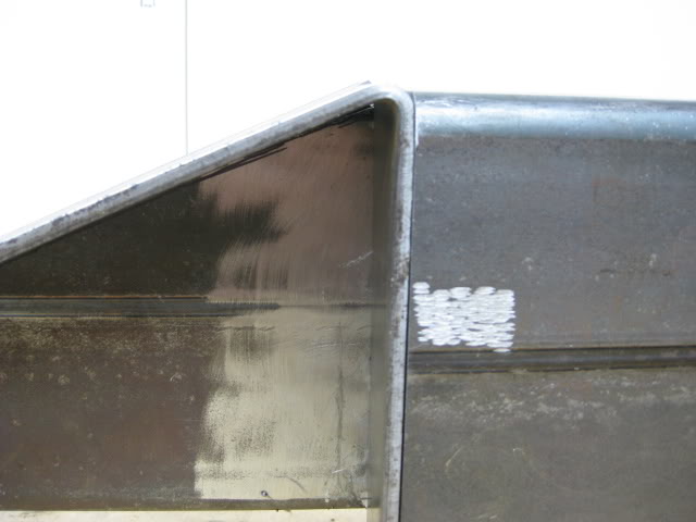
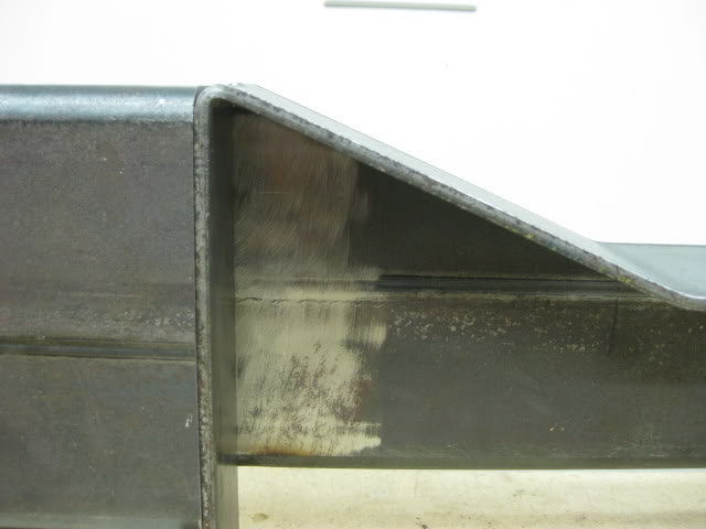
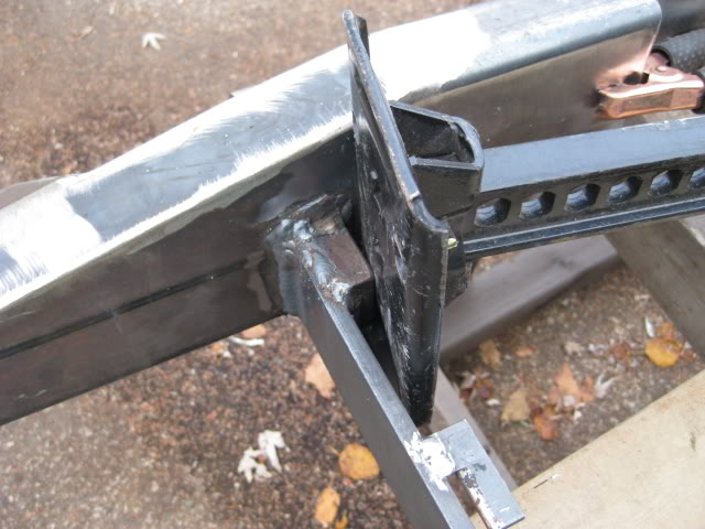
Now, this is my plan too make it all fit together and make it one unit, strong enough to carry the weight of the truck using the Hi-Lift on the side protection....
I'm still using the 2'' tube, clocked to 45*, from the bumper too the wheel well. The side protection tube on the bumper end will have a short inner square tube just big enough to fit inside the 2'' tube and weld in place to make it one piece. This inner tube will be slightly protruding out of the 2'' tube, enough to fit into the 2'' tubed corner of the bumper, It will be bolted in place possibly welded later in life. The intersecting side protection and bumper corner will be strong enough to carry the truck weight with the jack. Have I lost you yet? LOL!
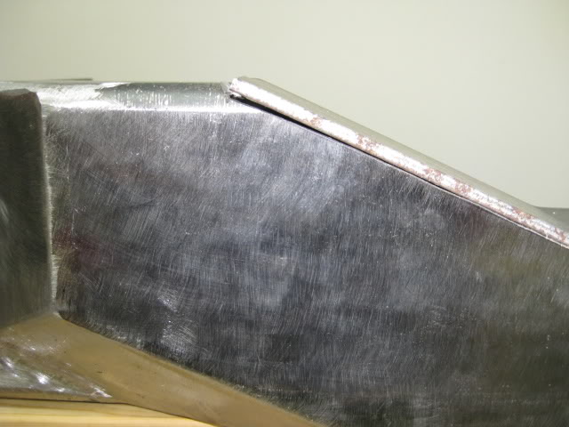
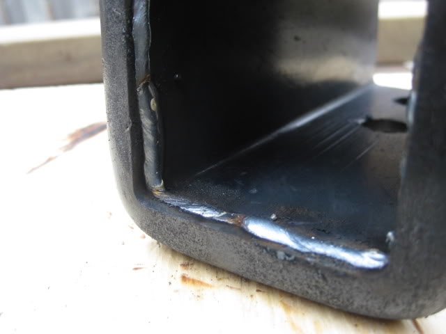
Here is a picture of the back side of the bumper corner to give you some idea. Like I said the side pro. is still in the design stage. If I decide to keep the bumper as is, without side protection, I can simply cap off the open corner so animals don't nest in there. I could weld in a thin plate or cap it off using trailer hitch receiver plastic caps. I'll mount the bumper in the spring and plastic cap the corners until the side protection is done ready for install.
Wow! What a long winded post! Sheesh!....... Its just a bumper! LOL....
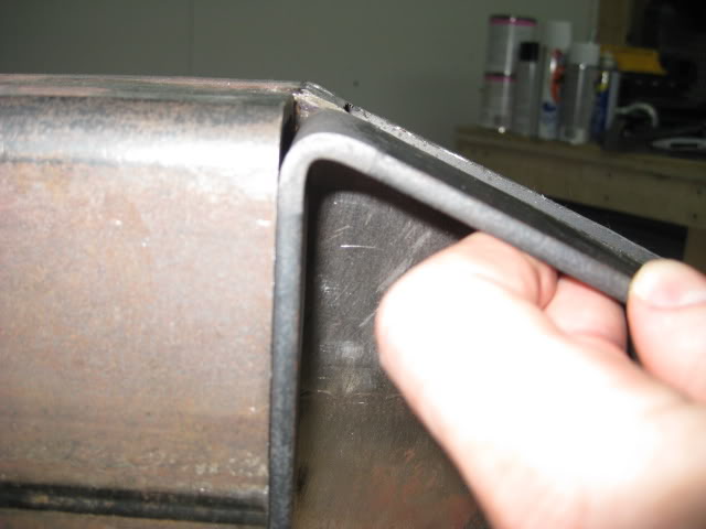
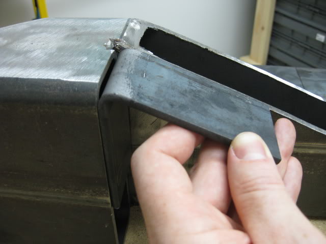
O.K. now for the front corner of the bumper..... Before I installed the corner 2'' square tube, I had to do some more creative cutting, again this was done on the band saw.
In order to get the angle I wanted, I had to weld the corner pieces to scrap tube so I can cut those crazy cuts. Here is a pic of the corner pieces welded to the scrap tube, but my camera battery died before I made the cuts..... .
Did I mention I'm going for the "Longest Forum Post Award".
Hmmm..... I wonder why my camera battery died?
Back on topic.... The corner pieces end up with 2 angles per piece, this pic shows one angle that was cut per piece...... I don't have a image of the piece when it was finally welded in.
Lately I was able to land a couple days of good weather and spare time.....Yippie!
The crazy corners finally had the outside surface plates ''welded in'' and shaped.
The plate went into the bender, thus eliminating a weld, it was a perfect fit.
I must have annoyed the hell out of my cool neighbors.... I whipped out that disk grinder! Mooo ha ha ha!
I was able to grind a fair amount. Later I'll go over the whole thing with flap disks to get a better finish.
There is still work to do...... The boxed hitch receiver, step plate and gussets, and the odd weld, here and there. These items are next on the agenda.
This brings me up too date! My fingers hurt..... wonder why?

As it sits right now...... At the present time my bathroom scale is telling me its a hefty 76 Lbs.....
Oh! just in case your wondering......I will be plating and possibly boxing the rear frame of the truck.
The hitch receiver needed some modification, it's one that I purchased a couple years ago. The problem with the receiver was the receiver lock pin hole location. The receiver would stick out to far reducing the departure angle.
If I mounted the receiver with the rounded cap against the surface of the bumper the receiver lock pin hole would have been in the middle of the boxed body of the bumper. It would be hard to patch the original 1/2'' holes.
If I mounted the hitch receiver with the holes inside the boxed bumper, water/ moisture would collect inside the bumper, especially during river fording.
The other issue I had with the receiver, was the length. I bought the long receiver over the shorter version, just in case. The extra length was not necessary. My solution is simply to shorten it.
The Receiver has a nice steel cap end with rounded corners, it's a nice touch. I plan on retaining the cap.
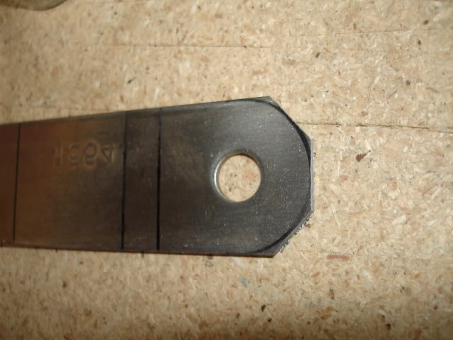
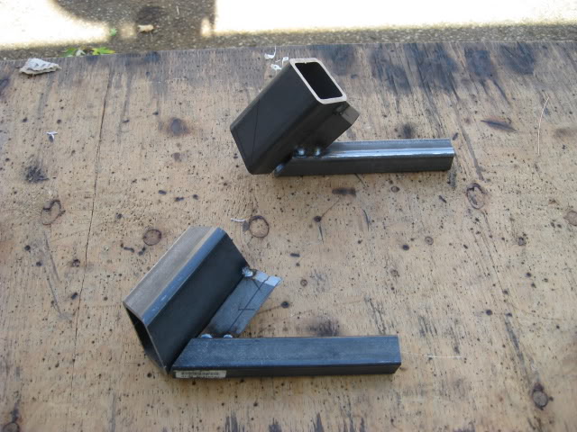
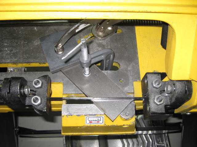
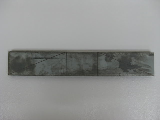
The problem with the cap was the location. I was going to grind the two 1.25'' welds off, but didn't feel like the extra work so I simply cut it off with the band saw, then I shortened the box receiver.
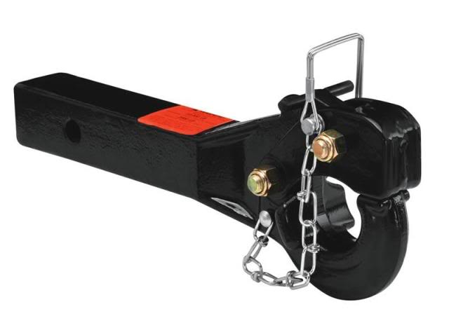
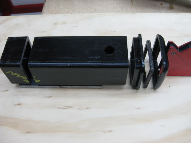
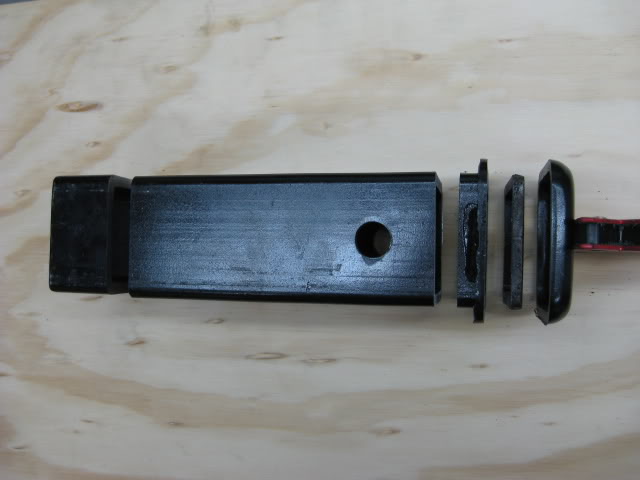
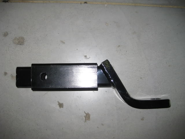
Before I started cutting, I took measurements of the ball mount I was planing on getting, I cut the length of the receiver down, so the original lock pin holes would except the ball mount. I needed a length of five inches from the front edge of the receiver with the cap in place to the hole center. This measurement also allows me to use a receiver style pintel Like the picture below.....
These pic's show how I cut the receiver into sections. The first pic is the original length, the receiver is cut in this pic, I re-assembled it for the sake of the pic.
The end cap has a nice recess to except the box part of the receiver, I'll will weld it back on. Instead of two welds and a crack to hold moisture for rust, I'll weld the cap all the way around to seal it up.
The pintel hitch would allow me to tow a off road trailer, like the Canadian Forces M101 utility trailer. The regular ball mount would allow me to tow a standard trailer.
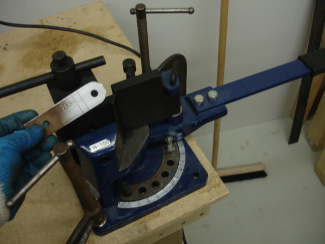
The next picture, I took the shortened receiver to the store. I thought I'd double check before I started welding the receiver in place....... I learned this lesson long ago... double check, then check again.
Since I was at the store, they had a whole rack of various ball mounts, some of the mounts, like the lower drop mounts, had a different spec for the hole positions.
I took some more measurements to drill a second set of holes, just in case I need to insert a different ball mount. I will, more than likely, need a drop ball mount as I lift the truck. Again, better safe than sorry. I'll kick myself if I didn't drill a second set of holes.
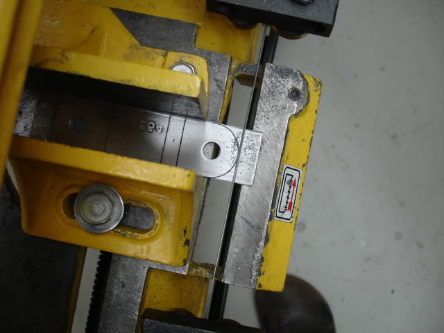
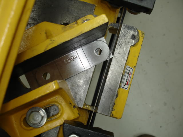
Here is the process to drill the holes.....
After marking my measurements on the box receiver, I drilled a guide hole for the 1/2'' drill bit.
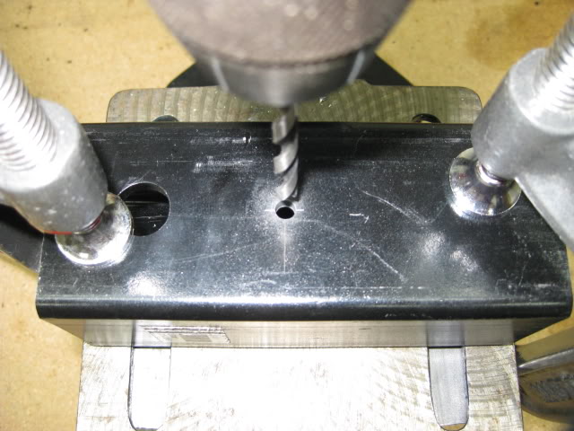
The guide holes were drilled on one side, then flipped and drilled on the other side.
The drill bit was way to shot to drill straight through, I would never do that anyway, even if the bit was long enough.
For my peace of mind and for the sake of precision, I used the drill bit as a gauge, to make sure the holes line up.
Now for the 1/2" hole......
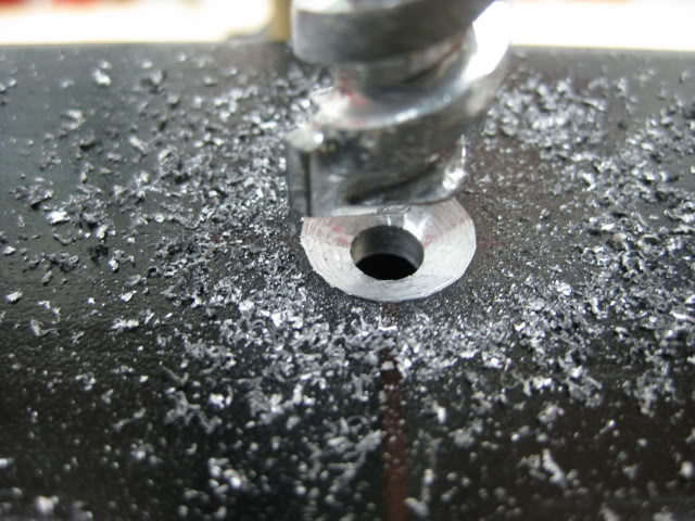
Ever since I drilled holes through a set of leaf springs, I've changed my choice of bit for drilling holes from 1/2'' up to the smallest size Bi-metal whole saw.
For a long time, I would use a metal drill bit. The problem I had with the larger drill bits was: heat, and screeching sound, and the fact I had to use a lot of lubricant to eliminate heat and sound, I can only drop the speed down so much, on my drill press.
If any one has tried drilling leaf springs with a metal cutting bit, they know how hard it is to drill that hole, bits dull in minutes. A trick I learned was to use Cobalt Concrete Drill Bits...... Ya! I was skeptical, until I tried it my self.
The bit cut through the leaf spring in no time, I was amazed! And the quality of the hole was amazing!
I used very little lubricant for the leafs, there was a lot less heat, it was warm to the touch, the noise level was a lot lower. That being said, I started using the concrete bits on thicker mild steel stock. Its like cutting through cheese.
Side note.... concrete bits are easy to sharpen, I use a grinding wheel. I sharpened the bit once since drilling into basement concrete floor, 4 holes through spring steel and 2-3/4'' mild steel blocks.
Here are a few pics of the concrete bit at work......
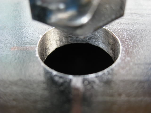
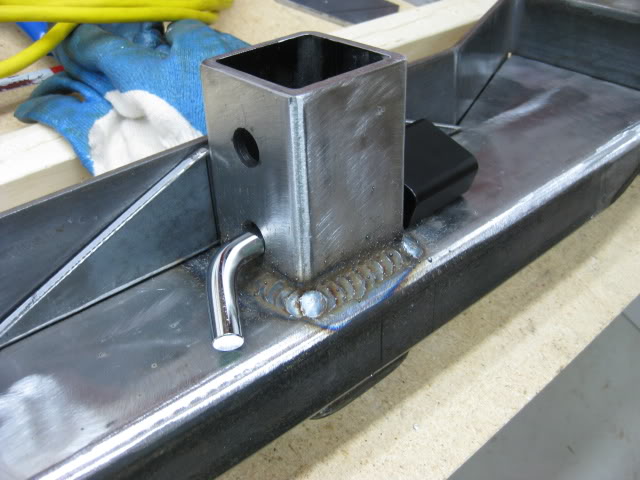
After the holes were drilled in the box receiver, I put the end cap back on the receiver, hand tight, not welded.....
I placed the receiver in position, made sure I could put the pin and lock in place to make sure I had the clearance.
Next step....... I made a gusset to re-enforce the receiver, and step plate, the gusset allows me to tie the box section of the bumper, receiver and step plate together for more strength and support.
I used 3/8'' flat stock for the gusset.
The 3/8'' gusset sits on top of the receiver, the step plate rests on the gusset. The parts will be welded together, later.
I plan on welding the box receiver on the inside and outside of the midsection of the bumper for extra strength.
The gusset is not totally done in the following pics, it needs some refinement...
Before I weld, I'm thinking of changing the design of the step plate.
I 'll get to that later..... it will be a experiment.
Here are the rough idea of how the gusset will be placed.....
Well.... I did a little more work.
I had to change things up a bit. I was not quite satisfied with the step plate.
this was the original step plate....
There was nothing wrong with the step plate, it was perfectly fine. I just wanted to improve on it and test my plate bender skills....
For $10 of plate steel, I had the itch to experiment.... The original plate is still useful for other projects, 3/16 is handy to have around.
The original step plate covers the center section, completing the box.
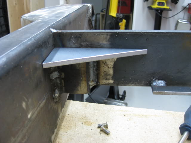
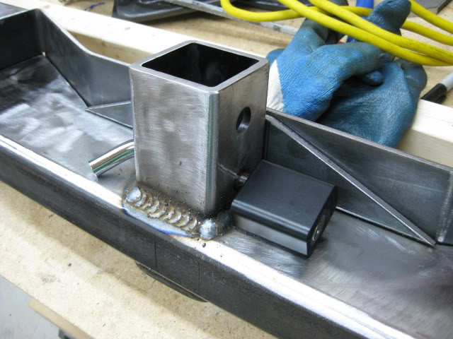
I still had to cover the driver and passenger side outer box sections adding end caps sealing the box and adding a little more strength possibly giving me a surface for another gusset, I'm still debating adding gussets to the box ends.
The area I'm talking about can be seen in the next pic, The open boxed end beside the magnet on the left.
Originally I was going to weld a piece of 2'' x 6'' x 3/16'' plate to cap the box, then weld the top plate in place.
I thought about eliminating the weld joining the step plate to the end caps, by incorporating the end caps into the step plate, the bend would be stronger then tricky and possibly questionable welds.
Anyway, thats the excuse I'm running with. LOL!
I just want to play with the bender some more....
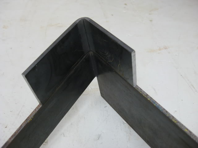
Before I went out to the steel store, I thought I'd do a test bend on some scrap steel, I had laying around.
I wanted to see if I could get the bend I needed to cap the outer box ends and achieve the angle plain for the top plate.
The test piece, was a piece of 2'' - 3/16'' plate. The test piece will also tell me where the bend will start on the new step plate, bending down to make a end cap.
The next few pics gave me a idea of how and if, it would work.
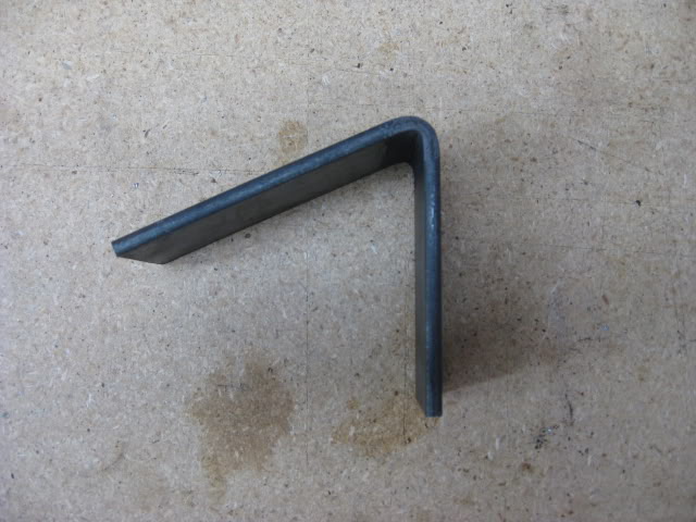
The test piece gave me a good idea of how the new step plate would be formed.
The test piece will be used as a sample / bend gauge. I can compare the bend, I'm bending, on the new plate, with a proven bend of the sample piece.
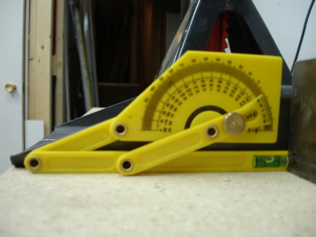
Sometimes a sample piece is better than using a folding protractor while bending, because it includes the metal thickness. I find it helps with this type of bender.
I was confident the new top plate idea would work. I didn't bother making a cardboard template but rather did the math taking in consideration the bends and surface lengths to get my over all stock length, then added extra just to be safe and round the length off.
Side note.....
The guys at the steel store are great. If I walk in wanting 38'' of stock they quote me a price, if I agree to round off the length off to 40'', they knock down the price.
The stock I bought was 40'' x 4'' x 3/16''....... 38'' would give me 1/2 '' extra stock after forming, on each side.
The price they quoted me for 38'' was $20.00. We rounded the total length to 40'', so they knocked off $5.00, not only that they also give me the option of buying clean stock or the greasy stock for $ 5 less.
The greasy stock is usually "off cuts" that have been sitting around the store for a while. Degreasing is not big deal.
If you buy smaller pieces of stock, ask the people at the counter if they will sell the off cut for a reduced price.
There are times I walk in, wanting a odd ball piece of steel, they'll just give me a piece that I can use, it may take some machining but it was free.
The store I deal with, sells mild steel stock, rounded off to the inch, they really don't have enough scrap to make it worth while to reclaim, rather they throw the odd stock on a rack and sell it at the book price. I've been loyal to this store, so they're willing to cut me deals, if I was a business that would be a different story.
I thought I'd share that with all of you to help you reduce cost. You won't know unless you ask.
Back to the job at hand....
I bought 40'' x 4" x 3/16'' stock, marked the stock for the cuts and bends....
The end caps are 2'' x 6'', I had to cut a couple of sections out in order to form the end caps. I left extra material, instead of cutting the end cap length to 6'' opting to cut after the new step plate has been dry fit. Better to have end caps longer than shorter. The cuts were done on the band saw.....
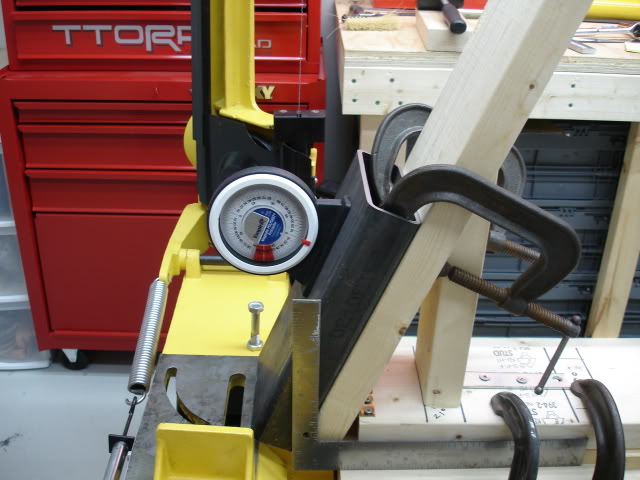
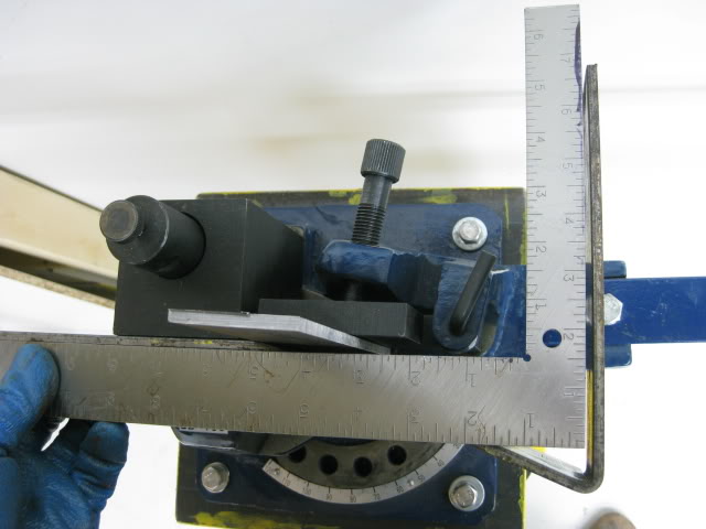
The end caps were the first bends formed on the step plate. I used the sample bend piece to help me get the bends I need. Bending a little at a time, checking the bend with the test piece, eventually I was able to get the exact bend I was after.
The following pics show the test piece, test piece compared to the bend on the step plate, shot from different angles.....

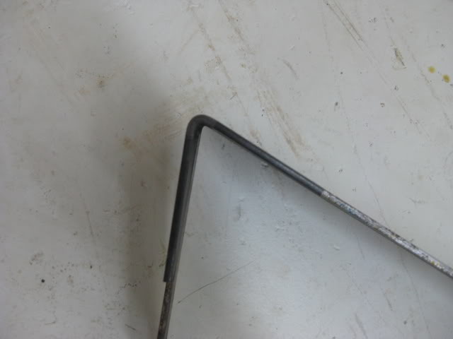
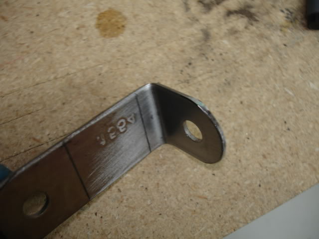
The first bend on the step plate, formed end cap....
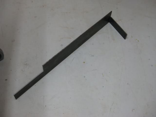
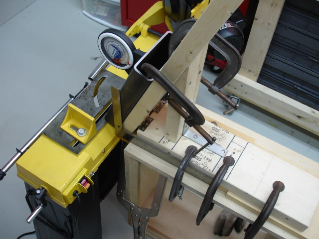
The second bend forming the end cap on the opposite end of the step plate....
The next step is to form the bends that make up the main section of the step plate.
The easiest way to ensure I get the proper bends, is to use a square.
The center of the step plate is square to the box ends to be caped, I will bend and check, bend and check until the the center of the step plate and end cap is square, then flip the plate and repeat the process forming the opposite side of the plate....
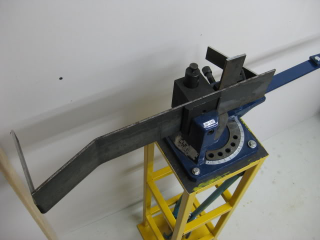
After the bends were double checked for accuracy it was time to do a dry fit.
I have to say it was tricky to get exact accuracy. I was damn close. It was a tight fit, in fact to tight, it is so close, out by 1/16'' each side. If I bend the angles on the plate that would shorten the overall width enough to fit, but it would throw my angles off this would be unacceptable. The easiest way to make this plate fit is to remove material from the box ends to be capped.....
Tight fit.....
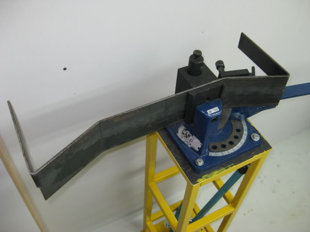
I thought about grinding away 1/16'' on the box end each side but it would be hard to get a uniform surface, so it was back to the band saw. This cut was a tough, angling the bumper just right, shaving 1/16'' of material off the box and hopefully finish the cut evenly on the back surface of the mid section box, without cutting into it. Anyway..... it came out perfectly.
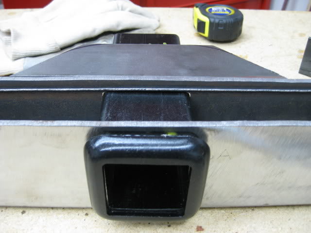
Back to another dry fit. This time the step plate fit the box ends exactly the way I wanted. Even thought the box ends fit, the top plate sits 3/16'' to high.
I want to countersink the plate 3/16'' so the driver and passenger side edges of the plate, are at the same plain as the top surface of the rest of the bumper.
I want as much edge material as possible at the bends, so I don't compromise the bend for the box ends, when I grind down the welds that will join the step plate and bumper top surface.
I may have to do a fill weld at the box end bend maybe 2-3 passes, I don't know yet.
This set of pictures shows the top plate sitting high, the plate fits nice on the box ends.....
Countersinking the top plate....
I had no choice but to do some creative grinding. This was not fun! In order to countersink the step plate I had to grind away 3/16 of the exposed edge of the box section wrere the step plate will sit.
First step was to mark the depth of the material that will be removed. The trick is to be uniform and avoid doing a hack job, this is a tiring job with a large disk grinder. It would be a piece of cake with a plasma cutter.
After a while I managed to get, somewhat uniform edges. If I clamp the plate down the edges sit flush. I'l go back and touchup the edge surface with a Dremel before I weld, relying less on the clamps.
Because I modified, how the step plate fits, buy removing 3/16, I can no longer use the 3/8'' gusset between the step plate and box receiver.
I'll be replacing the gusset with a piece of 1/4'' thick gusset. 1/4'' seems to be a snug fit. The 1/4'' gusset + 3/16'' step plate welded together, should be fine as a gusset, for the box hitch receiver.
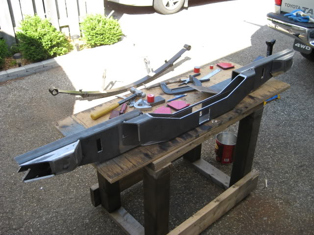
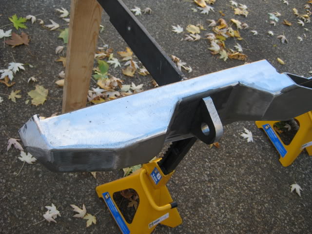
This is how the bumper looks with the step plate and hitch receiver, dry fitted.
The next step is welding the receiver and step plate in place and add gussets where the mounting brackets and bumper meet, at the top of the recovery point bracket.
Well.... I managed to land a nice day, weather wise, so I thought I'd take advantage.
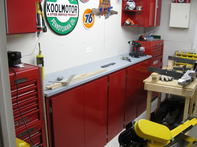
Before I start talking about the bumper, I thought I'd show off another project, a new work bench.
The doors are not mounted yet, they're propped up in place for the sake of the picture. I had some scrap wood kicking around, so what the heck... new storage work bench. Its not done yet. I'm adding a back and side splash to keep the shavings from falling behind and off the sides of the bench. Bling Bling! Eh?
O.K. back to the bumper....
The first order of business.... I made a new gusset. I replaced the original gusset, the original was 3/8'', I replaced it with a 1/4'' gusset, after I did some grinding to countersink the step plate as mentioned in my previous post . It was a change for the better.
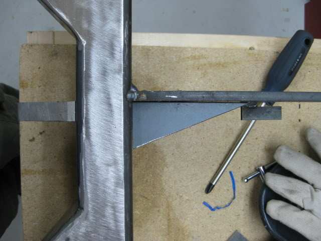
The new gusset has a longer triangulation, the length of the new gusset is 12'' long, the same width as the flat part of the step plate.
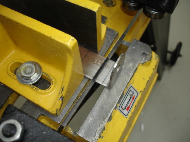
Again, I cut the plate stock on my trusty band saw.
The off cuts will be used for the mounting bracket reinforcement gussets.
The off cut pieces will form a long triangulation. If I use a triangular gusset at 45*, the gusset would be big. The gusset covers the recovery clevis sticking out of the backside of the bumper. You can see the back side of the clevis in the fourth picture. The longer triangular gusset fits better than a 45* gusset and I'm making the most out of the 12'' stock.
Hitch box receiver.....
The receiver had a powder coating as a finish, the coating had to come off for welding. I used a flap disk on a grinder to remove the powder coating. The receiver cap edges were cleaned up as well.
Originally, the cap was welded on, using two 1'' (approx.) welds, leaving a crack around the the cap and receiver, a great place for rust to form.
I decided to attach the cap, welding all the way around to eliminate the crack.
The inside of the receiver also had a crack, so I sealed it up with smaller welds. The inside welds will be ground flat to retain the original dimensions, other wise I'll look like a dumb ass, trying to mount a ball mount.
Unfortunately, I wasn't able to grind the inside weld today, I'll do that later in the shop.
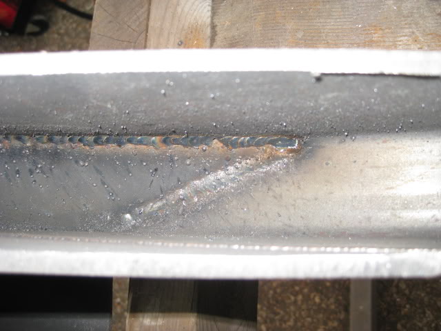
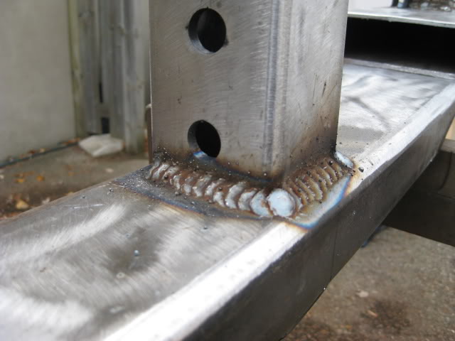
Oh! I remembered to take a pic of the weld on the inside of the bumpers box midsection, welds reinforcing the inside angular plates that give the bumper it's shape.
These welds were tricky, there's a lot of slag that I will try to clean up.
A blob of lithium grease will be added to the inside of the box to catch slag rolling around reducing the little rattling sounds.
Not that I'll be able to hear it on the trail anyway LOL. At work we use grease on the inside of car seat frames, to catch loose punch slugs and weld slag.
It makes a big difference in noise reduction on car seats. The seat is closer to your ear than a bumper, I hope! But what the heck... I'm doing it because I have grease and because I just wouldn't feel right not doing it.... sheesh, thats what happens after welding 2 million car seats. LOL!
The grease will be added to the box sections before they're sealed up.
There you have it! Justification! LOL.
The internal welds......
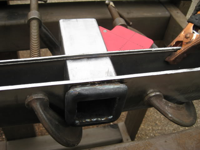
Now its time to weld the hitch box receiver to the bumper.
The receiver was welded 360* around on the front and back.
The welds on the inside of the box section of the bumper have welds on the top and sides, front and back. I did this for more strength. Tricky internal welds but it came out fairly good.
There was room left to apply weld behind the front receiver cap. I wanted good welds in there. I didn't want to weld the outside edge of the cap to the bumper face, besides, there are welds on the back side of the cap, preventing me from mounting it flush. A leveling weld will be added later and ground flush making the cap look like its one piece to the bumper....... Oooh Wow!
Before the receiver was welded in, I made sure the receiver holes on the backside had enough room for the receiver / ball mount lock, with room for welds.
Can't forget that!
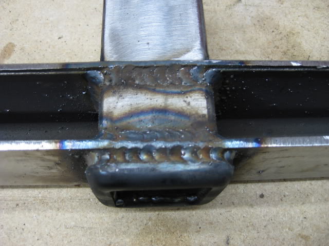
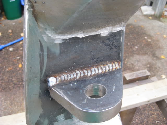
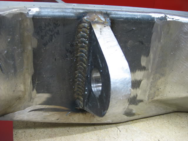
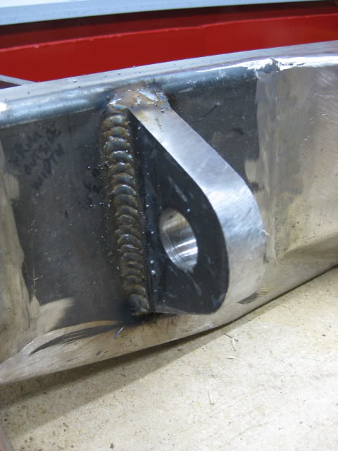
While I was at it, I finally added welds 360* around the recovery points (clevis points)
I took my time, was running low on gas, but managed to get it done. Clevis edges will be rounded out, buzzing the edges with a die grinder and refined with a Dremel.
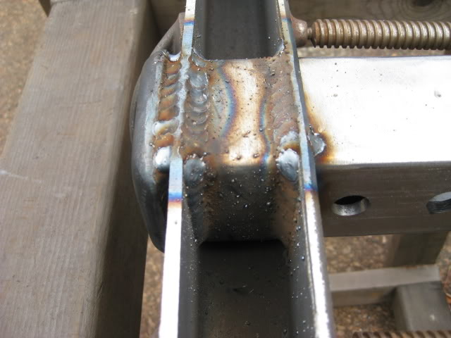
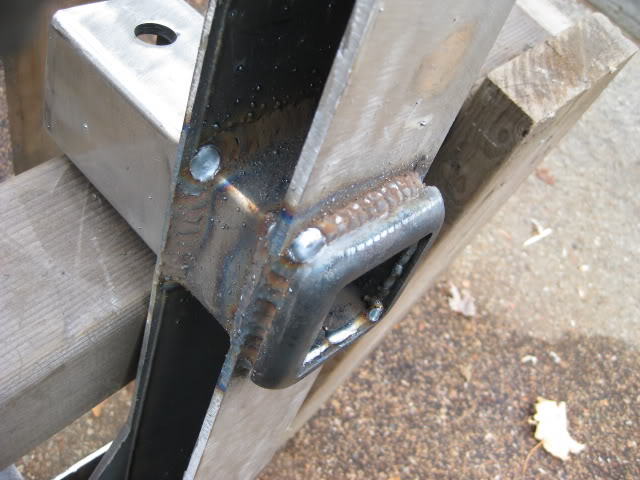
With gas running low, I figured I could still get away with welding in the gussets for the frame mounts.
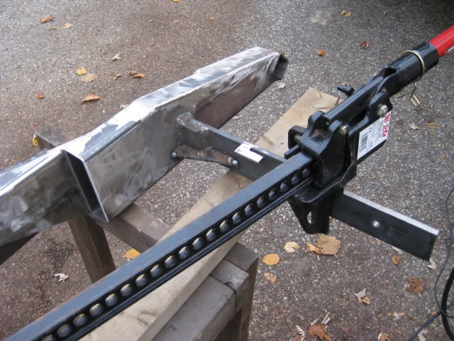
Long semi supported steel tends to bend with heat from welds. To prevent skewing the distance between the two mounting brackets from heat, I used my Hi-Lift jack to slightly spread the brackets supporting the original spec. I welded one side first, then flipped the jack to the other side and welded the gusset.
By spreading the brackets by 1/4 '' more than spec. I can assure the brackets will still line up with the truck frame.
If the spec. is a tad wider that's fine, if it's narrow because of heat warping, that's bad.
So I decided to play it safe. I let the welds cool down to the touch before I removed the jack. In the end the distance between the brackets was increased by 1/8'', total, so I know the spec is still good.
The gussets welded in place....
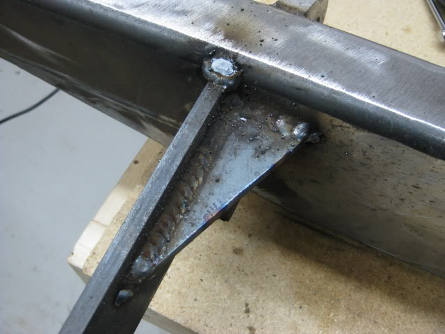
With shielding gas and sun light running low, I wasn't able to weld the step plate and gusset in place. Instead I brought the bumper back in the shop and took some pics of the receiver lock, step plate and gusset in place to give you a idea of how it will be pieced together......
It's suppose to rain for the next three days, I'm hoping there will be a nice day next week and hopefully finish the main part of the bumper.
Well, I thought last week, all I needed was one more day of work....
Ya right!
O.K..... Now, all I need is one more day of work...... I think....... LOL.
I'm posting the process, step by step possibly creating one of the longest single post threads. It might help people with their own bumper builds, then again it might not.
I've been working on and off, building this boat anchor for a while, in my spare time, when the weather is nice enough to weld in my driveway. Lately, I've had time to work on it, thanks to our global economic fun-fest. Gee thanks boss!
Right now I'm trying to finish the main part of the bumper before the snow flies. The weather will beat me too the punch, but what can you do?
I need a garage. In the mean time, I make due.
The main reason for the bumper build is... for the sake of building. It's fun! Maybe not for the neighbors, but hell you only live once. I'm sure they'll get over it.
I'm sure the they cringe every time I whip out that grinder.
Mooo ha ha ha...
I'm handing out ear plugs to the parents for Halloween.
So far my fabricating addiction and my love of noise hasn't been a issue with the neigbours, their pretty cool.
I want some beefy "ass" protection! The OEM bumper held up like a champ taking on 4 rear end fender benders, resulting in one minor dent.
The OEM bumper will be my future beer bar in my work shop..... Yippee!
I want something that will scare people into not hitting me... if they do, they're in for some big damage. Other important requirements... tow and recovery points.
I went out of my way to take enough photos to give this thread some "meat", documenting the main steps of the build.
I thought about copying other designs but opted for originality, something different to test my skills.
The design is different but beefy, possibly deflect bullets and give the illusion of stealth technology to thwart radar guns..... I have a vivid imagination. LOL.
The bumper is made primarily of 3/16'' , 1/4'', 3/8" stock - plate and rectangular steel tube.
3/4'' stock was used for the Clevis recovery points, I could have bought them, but thought... " What the hell, I'll fabricate them myself.
I incorporated a trailer hitch box receiver just in case I decide to tow something like a M101 military trailer, if I ever decide to get one...
Possible future build.
I plan on cutting the rear quarter panel for high clearance. The bumper will accommodate side panel, detachable, high clearance square tube protection, yet to be designed and built. The side protection attaching points have been incorporated into the corners of the bumper..... you'll see.
I'm also adding brackets for rock lights on the inside of the bumper.
Air lines: female couplers will de added. on either side and rear of the bumper, for tire inflation and the air mattress for our tent. I thought about turning the bumper into a air tank for use on the trail, but a tankless, good air compressor will do just fine, I'm not in a race.
The bumper and side protection will be strong enough to use a Hi-Lift jack.
A swing out tire gate will be designed, steel cut and dry fit this winter in my basement shop, ready for welding in the spring. Unless I come up with another solution for the spare tire.
The bumper will not be installed until spring, I'm not planning on wheeling this winter anyway.
This spring my truck will see real transformation when the pile of parts are finally glued to the truck. I'm in no rush, there are still a few parts I need anyway.
The main tools I used were:
- A frickin loud disk grinder
- die grinder
- Miller 175
- my trusty band saw (I love that thing!)
- various magnets
- my hands and brain
- ruler, level
- air wrench
- jack stands
- camera
- flat stock bender
- blowtorch
- drill press
- jig saw
- Beer
- belt / table grinder.... and a few other tools, I can't think of right now.
Well enough jibber Jabber, heres the build.....
First thing I did after making some sketches and taking measurements and buying stock, is cut the rectangle tube stock into the lengths and angles needed.....
I'm not including the pics of my drawings, they were destroyed by a beer explosion. I'll build up the drama by posting sequence pics. LOL...
Next I cut the box tube for the driver and passenger side higher clearance profile....
Clevis recovery points...... The next thing on the agenda.
I used 3/4'' steel blocks. This build was a complete experiment, largely due to the fact, I was using a Master Craft hobby bench-top drill press and 1'' Bi-Metal hole saw. LOL...... Lets just say I put this machine to the test and then some.
I'm very impressed with this drill press. I will be upgrading it eventually, hopefully with a mill drill or milling machine.
The key to drilling thick steel with this drill press is:
- dropping the dill speed as low as possible
- clamp the work so nothing shifts
- drill a small diameter guide hole
- use a lot of cutting lubricant.
I took my time, keeping the heat down, stopping to cool the motor, in the mean time I used a Shop Vac to remove metal shavings.
I didn't force the pressure on the drill press to speed up the cut!
After drilling two hole with the hole saw, the saw was still sharp.
You'll notice I put the drill press in a bucket, with some card board taped too the inside of the bucket. This was my solution to keep the sloppy mess down, making it easier to clean up.
The hole saw cut turned out better than I though.
the next step was too cut the 3/4'' stock into the shape of a clevis point....
Back too the band saw... The cuts take a while. While I sat there baby sitting the saw, Godzilla was entertaining me... Godzilla vs. Mothra. Classic!
I love monster movies.
The next step was giving the cut edges of the clevis a smooth finish, for this I used a table disk/ belt grinder.
The clevis I designed is meant to go through the bumper, welded on either side, front and back of the bumper, as well as the inside of the boxed section of the bumper. Over kill!
The clevis will be connected to the mounting brackets that attach directly to the frame.
I used two pieces for the clevis points welding them together too make one piece. I beveled the edges of the clevis parts were the weld would be applied. I managed to get pretty good penetration. I put one of the clevis points in a vise and gave it a couple good wacks with a hammer to see if it would crack the weld. All was good so I ground the excess weld down to clean up the surface.
The bumper corners are unique. The main purpose for this is: Too give the bumper some extra beef and depth, more area to" weld in" hinge towers with gussets for the swing out gate, recess the clevis points so they don't stick out too far on the out side surface of the bumper, and.....
To be different.
I used the band saw to create the main pieces for the corners.... confused yet?
I used card board for the plate templates to get the general shape....
I used 3/16'' plate steel for the angled surfaces....
Ok here is the basic layout of the bumper on the work bench....
The next pic shows the basic pieces for the main part of the bumper....
A box trailer hitch receiver is part of the bumper design. I wanted to keep the receiver as high clearance as possible. In order to achieve this I had to cut a 2-5/8'' x 2-5/8'' square hole out of the bumpers mid section to fit the receiver through the bumper.
This step was another challenge. It would be a piece of cake if I had a plasma cutter. I could have called a family member that has a plasma cutter but I like doing things the hard way.
I was up for another challenge and devised a plan.....
Taken from a old-school tool and die technique, I perforate the rectangle box with a drill press. After perforating both sides of the box section, I used a jig saw to cut through the perforations. Worked like a charm! I didn't bother grinding the inside edges flat. I ground just enough to fit the box receiver through the bumper, nice and square.
See! I don't need a stinking plasma cutter!
Ya right! ....I just can't afford one right now.
Unfortunately this is the only pic of this step, you'll be able to see it in later pics.... I think.
Back to the bumper corners.... I welded the angled plates into position and ground the welds, smoothing them out. I also used a hole saw to drill out holes on the backside to lighten up the corners.....
What a time too nickel and dime. If I had a plasma cutter I would have removed more steel.
For the most part the fancy corner thing-a-mabobs do not weigh all that much.
( I'm doing a 63'' rear Chevy leaf spring swap so the weight factor is a not all that bad, although that may change if I decide to mount a spare tire gate, I may have to add a forth leaf, but thats another build.).
The outside corner edge looks pretty scary!
I notched out the corner to accommodate square tube for the side quarter panel protection ( trimming the fender for higher clearance) originally I was going to mount the tube square to the ground, but just to complicate things I decided to clock the tube 45*
The next photo shows what I had in mind regarding the 45*...... Fancy, eh?
During the build I would assemble the parts, take a picture or two and think about what I have, making sure it will still work.
After looking at theses pics, I decided I could lighten up the bumper, a bit, by taking out a section of the center piece above the receiver hitch. this would possibly help lower the height of a spare tire, I won't know until I get to that stage. Another use for the change would be a step. It could be handy for adjusting loads and straps on my roof rack. The step would also transform the bulky look of the mid section.
I'm also using the step plate as part of the gusset for the hitch receiver and re-box the mid section.
I used my trusty band saw to remove the material to create the step. It was a slow process.
It's amazing what you can do with a band saw. I used the drill press again too drill the corners so I can pivot the band saw blade too cut straight across the box mid section.
Here's the mid section from different angles....
The after pic of the mockup assembly.....
After the mid section step was cut and evaluated over a cold beer. The next step was creating a step plate.
I thought about using diamond plate but after visiting the steel store, my measurements and cardboard template indicated diamond plate would not be the best solution.
I wanted to use a one piece plate with bends rather than three plates welded together to create the angle.
I have a plate and angle iron pedestal bender. (another tool, I love!)
The diamond plate would be hard to bend, the diamond pattern also didn't work well with the measurement I had.
I decided to go with 3/16'' standard flat plate steel.
I can add a anti slip surface later in the build..... Like grip tape, spray on / roll on bead liner, or weld my forum name / signature on the surface of the plate.... the creative juices are flowing again. LOL.
Anyway......
Before I do any bending, I double checked the measurements with the template, cut the plate to a slightly longer length (just in case), mark the plate where the bend will be, Place the plate in a vice and add heat. I used a MSP* gas (methylacetylene propadiene, stabilized.), also known as MAPP gas. I used this gas over propane because it will burn hotter. The hotter the bend location is, the easier it is to bend the steel, creating a sharper bend Some times a radius bend will occurs with cool steel, heat is required with this type of bender.
Here's an ugly of me, the bender and the result......
Tack weld time!
Well, before I get ahead of myself, the Clevis points mount through the bumper, I figure the recovery points will be stronger that way, rather than welding the clevis points to the surface of the boxed section with no material between the recovery point and the frame brackets.
I used the same technique to remove material, as I did for the hitch box receiver... perforation holes with a drill press and cut with a jigsaw.
Back to the tack welds. I had the measurements of the outside frame width. Having measurements, I tacked up the bumper so the out side edge of the clevis points match the width if the outside mounting surface of the truck frame.
With the tack welds in place, it gave me a rough idea of how much I would have to tweak the distance between the clevis point to make the new mounting brackets fit the frame. I ended up grinding off the tack welds three times to get the proper distance between mounting brackets.
Bumper mounting brackets: I used 3/8'' steel stock.
Before cutting and drilling, I used cardboard as a template to locate the OEM mounting holes on the truck frame and weld locations of the OEM shackle hanger welds.
After cutting and drilling the mounting brackets, I did a dry fit to make sure the bracket holes match the frame holes, I bolted the brackets to the frame and took bracket length measurements so I can cut them to the proper length. Then removed them.
I took the time to fabricate bracket tabs to help support the bumper weight on the inside of the frame, while mounting the bumper, just like the OEM tabs.
The tabs make it easier for one person ( me ) to position the bumper on the frame. I then position jack stands under the main part of the bumper to carry the bulk of the weight while I bolt the bumper to the frame. Its a real back saver.
Next, I tack welded the brackets to the clevis points, them mounted the bumper on the truck. Like I indicated earlier, it took three attempts to get the distance between the brackets right to match the frame width. I managed to get a perfect fit. While I was at it, I welded the top of the corner thing-a-mabobs so I can grind the welds flat to make the bumper top surface look like one piece. Grinding came later.
Its tricky welding outside, the wind tends to blow the shielding gas away, I managed to get some half decent welds. There was a lot of weld applied to fill the gap between the pieces, I then added smaller filler welds to even it out.
Again I took pictures of the bumper, earlier, of the boxed hitch receiver and step plate, in their rough position to get an idea of how they will fit. That way I can sit back in the evenings and think, without wasting the day away dreaming about the solution, with the bumper in front of me. If I had a garage that might be a different story, and I don't feel like lugging that thing down stairs.
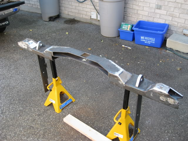
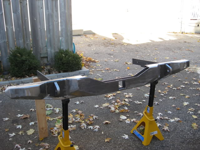
This is the bumper mounted at the tack weld stage. The result was a perfect fit.
Scary corners eh? LOL. It made a few friends scratch their heads. Its a fricken weapon!
Finally it's time to weld the angle plate pieces in place, to box up the bumper and get the bumper shape I was after.
The plate pieces tacked in place. The pieces butt up together create a ''V'' this gave me the opportunity to get deeper weld penetration.
With a deeper weld penetration I could grind the weld too a smooth shape without loosing too much weld integrity. All the plate welds on the front of the bumper were treated this way. I would only grind off enough weld to smooth them out.
Now, its time to tame the bumper corners, make it less of a weapon.....
Earlier I mentioned I was planning to trim the rear bed quarter panels for higher clearance and add side protection using 2'' square tube. This is still in the design stage. Although I did get a head start.
As mentioned earlier, I was going to mount the square tube, square to the ground, but instead I decided to clock the tube 45*, just too be different....
I was going to "weld in" full length tube to meet the edge of the wheel well, but decided to make the side protection detachable. This would make the bumper easier to man handle during the install, and removable incase I need to replace or change side protection, or just leave the bumpity bump the way it is without side protection. I like having these options. I have all winter to think about it.
Now, this is my plan too make it all fit together and make it one unit, strong enough to carry the weight of the truck using the Hi-Lift on the side protection....
I'm still using the 2'' tube, clocked to 45*, from the bumper too the wheel well. The side protection tube on the bumper end will have a short inner square tube just big enough to fit inside the 2'' tube and weld in place to make it one piece. This inner tube will be slightly protruding out of the 2'' tube, enough to fit into the 2'' tubed corner of the bumper, It will be bolted in place possibly welded later in life. The intersecting side protection and bumper corner will be strong enough to carry the truck weight with the jack. Have I lost you yet? LOL!
Here is a picture of the back side of the bumper corner to give you some idea. Like I said the side pro. is still in the design stage. If I decide to keep the bumper as is, without side protection, I can simply cap off the open corner so animals don't nest in there. I could weld in a thin plate or cap it off using trailer hitch receiver plastic caps. I'll mount the bumper in the spring and plastic cap the corners until the side protection is done ready for install.
Wow! What a long winded post! Sheesh!....... Its just a bumper! LOL....
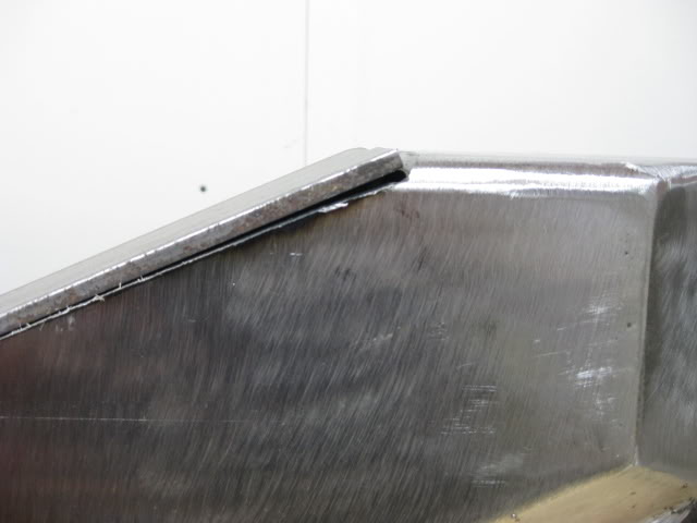
O.K. now for the front corner of the bumper..... Before I installed the corner 2'' square tube, I had to do some more creative cutting, again this was done on the band saw.
In order to get the angle I wanted, I had to weld the corner pieces to scrap tube so I can cut those crazy cuts. Here is a pic of the corner pieces welded to the scrap tube, but my camera battery died before I made the cuts..... .
Did I mention I'm going for the "Longest Forum Post Award".
Hmmm..... I wonder why my camera battery died?
Back on topic.... The corner pieces end up with 2 angles per piece, this pic shows one angle that was cut per piece...... I don't have a image of the piece when it was finally welded in.
Lately I was able to land a couple days of good weather and spare time.....Yippie!
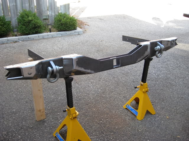
The crazy corners finally had the outside surface plates ''welded in'' and shaped.
The plate went into the bender, thus eliminating a weld, it was a perfect fit.
I must have annoyed the hell out of my cool neighbors.... I whipped out that disk grinder!
Mooo ha ha ha! I was able to grind a fair amount. Later I'll go over the whole thing with flap disks to get a better finish.
There is still work to do...... The boxed hitch receiver, step plate and gussets, and the odd weld, here and there. These items are next on the agenda.
This brings me up too date! My fingers hurt..... wonder why?
As it sits right now...... At the present time my bathroom scale is telling me its a hefty 76 Lbs.....
Oh! just in case your wondering......I will be plating and possibly boxing the rear frame of the truck.
The hitch receiver needed some modification, it's one that I purchased a couple years ago. The problem with the receiver was the receiver lock pin hole location. The receiver would stick out to far reducing the departure angle.
If I mounted the receiver with the rounded cap against the surface of the bumper the receiver lock pin hole would have been in the middle of the boxed body of the bumper. It would be hard to patch the original 1/2'' holes.
If I mounted the hitch receiver with the holes inside the boxed bumper, water/ moisture would collect inside the bumper, especially during river fording.
The other issue I had with the receiver, was the length. I bought the long receiver over the shorter version, just in case. The extra length was not necessary. My solution is simply to shorten it.
The Receiver has a nice steel cap end with rounded corners, it's a nice touch. I plan on retaining the cap.
The problem with the cap was the location. I was going to grind the two 1.25'' welds off, but didn't feel like the extra work so I simply cut it off with the band saw, then I shortened the box receiver.
Before I started cutting, I took measurements of the ball mount I was planing on getting, I cut the length of the receiver down, so the original lock pin holes would except the ball mount. I needed a length of five inches from the front edge of the receiver with the cap in place to the hole center. This measurement also allows me to use a receiver style pintel Like the picture below.....
These pic's show how I cut the receiver into sections. The first pic is the original length, the receiver is cut in this pic, I re-assembled it for the sake of the pic.
The end cap has a nice recess to except the box part of the receiver, I'll will weld it back on. Instead of two welds and a crack to hold moisture for rust, I'll weld the cap all the way around to seal it up.
The pintel hitch would allow me to tow a off road trailer, like the Canadian Forces M101 utility trailer. The regular ball mount would allow me to tow a standard trailer.
The next picture, I took the shortened receiver to the store. I thought I'd double check before I started welding the receiver in place....... I learned this lesson long ago... double check, then check again.
Since I was at the store, they had a whole rack of various ball mounts, some of the mounts, like the lower drop mounts, had a different spec for the hole positions.
I took some more measurements to drill a second set of holes, just in case I need to insert a different ball mount. I will, more than likely, need a drop ball mount as I lift the truck. Again, better safe than sorry. I'll kick myself if I didn't drill a second set of holes.
Here is the process to drill the holes.....
After marking my measurements on the box receiver, I drilled a guide hole for the 1/2'' drill bit.
The guide holes were drilled on one side, then flipped and drilled on the other side.
The drill bit was way to shot to drill straight through, I would never do that anyway, even if the bit was long enough.
For my peace of mind and for the sake of precision, I used the drill bit as a gauge, to make sure the holes line up.
Now for the 1/2" hole......
Ever since I drilled holes through a set of leaf springs, I've changed my choice of bit for drilling holes from 1/2'' up to the smallest size Bi-metal whole saw.
For a long time, I would use a metal drill bit. The problem I had with the larger drill bits was: heat, and screeching sound, and the fact I had to use a lot of lubricant to eliminate heat and sound, I can only drop the speed down so much, on my drill press.
If any one has tried drilling leaf springs with a metal cutting bit, they know how hard it is to drill that hole, bits dull in minutes. A trick I learned was to use Cobalt Concrete Drill Bits...... Ya! I was skeptical, until I tried it my self.
The bit cut through the leaf spring in no time, I was amazed! And the quality of the hole was amazing!
I used very little lubricant for the leafs, there was a lot less heat, it was warm to the touch, the noise level was a lot lower. That being said, I started using the concrete bits on thicker mild steel stock. Its like cutting through cheese.
Side note.... concrete bits are easy to sharpen, I use a grinding wheel. I sharpened the bit once since drilling into basement concrete floor, 4 holes through spring steel and 2-3/4'' mild steel blocks.
Here are a few pics of the concrete bit at work......
After the holes were drilled in the box receiver, I put the end cap back on the receiver, hand tight, not welded.....
I placed the receiver in position, made sure I could put the pin and lock in place to make sure I had the clearance.
Next step....... I made a gusset to re-enforce the receiver, and step plate, the gusset allows me to tie the box section of the bumper, receiver and step plate together for more strength and support.
I used 3/8'' flat stock for the gusset.
The 3/8'' gusset sits on top of the receiver, the step plate rests on the gusset. The parts will be welded together, later.
I plan on welding the box receiver on the inside and outside of the midsection of the bumper for extra strength.
The gusset is not totally done in the following pics, it needs some refinement...
Before I weld, I'm thinking of changing the design of the step plate.
I 'll get to that later..... it will be a experiment.
Here are the rough idea of how the gusset will be placed.....
Well.... I did a little more work.
I had to change things up a bit. I was not quite satisfied with the step plate.
this was the original step plate....
There was nothing wrong with the step plate, it was perfectly fine. I just wanted to improve on it and test my plate bender skills....
For $10 of plate steel, I had the itch to experiment.... The original plate is still useful for other projects, 3/16 is handy to have around.
The original step plate covers the center section, completing the box.
I still had to cover the driver and passenger side outer box sections adding end caps sealing the box and adding a little more strength possibly giving me a surface for another gusset, I'm still debating adding gussets to the box ends.
The area I'm talking about can be seen in the next pic, The open boxed end beside the magnet on the left.
Originally I was going to weld a piece of 2'' x 6'' x 3/16'' plate to cap the box, then weld the top plate in place.
I thought about eliminating the weld joining the step plate to the end caps, by incorporating the end caps into the step plate, the bend would be stronger then tricky and possibly questionable welds.
Anyway, thats the excuse I'm running with. LOL!
I just want to play with the bender some more....
Before I went out to the steel store, I thought I'd do a test bend on some scrap steel, I had laying around.
I wanted to see if I could get the bend I needed to cap the outer box ends and achieve the angle plain for the top plate.
The test piece, was a piece of 2'' - 3/16'' plate. The test piece will also tell me where the bend will start on the new step plate, bending down to make a end cap.
The next few pics gave me a idea of how and if, it would work.
The test piece gave me a good idea of how the new step plate would be formed.
The test piece will be used as a sample / bend gauge. I can compare the bend, I'm bending, on the new plate, with a proven bend of the sample piece.
Sometimes a sample piece is better than using a folding protractor while bending, because it includes the metal thickness. I find it helps with this type of bender.
I was confident the new top plate idea would work. I didn't bother making a cardboard template but rather did the math taking in consideration the bends and surface lengths to get my over all stock length, then added extra just to be safe and round the length off.
Side note.....
The guys at the steel store are great. If I walk in wanting 38'' of stock they quote me a price, if I agree to round off the length off to 40'', they knock down the price.
The stock I bought was 40'' x 4'' x 3/16''....... 38'' would give me 1/2 '' extra stock after forming, on each side.
The price they quoted me for 38'' was $20.00. We rounded the total length to 40'', so they knocked off $5.00, not only that they also give me the option of buying clean stock or the greasy stock for $ 5 less.
The greasy stock is usually "off cuts" that have been sitting around the store for a while. Degreasing is not big deal.
If you buy smaller pieces of stock, ask the people at the counter if they will sell the off cut for a reduced price.
There are times I walk in, wanting a odd ball piece of steel, they'll just give me a piece that I can use, it may take some machining but it was free.
The store I deal with, sells mild steel stock, rounded off to the inch, they really don't have enough scrap to make it worth while to reclaim, rather they throw the odd stock on a rack and sell it at the book price. I've been loyal to this store, so they're willing to cut me deals, if I was a business that would be a different story.
I thought I'd share that with all of you to help you reduce cost. You won't know unless you ask.
Back to the job at hand....
I bought 40'' x 4" x 3/16'' stock, marked the stock for the cuts and bends....
The end caps are 2'' x 6'', I had to cut a couple of sections out in order to form the end caps. I left extra material, instead of cutting the end cap length to 6'' opting to cut after the new step plate has been dry fit. Better to have end caps longer than shorter. The cuts were done on the band saw.....
The end caps were the first bends formed on the step plate. I used the sample bend piece to help me get the bends I need. Bending a little at a time, checking the bend with the test piece, eventually I was able to get the exact bend I was after.
The following pics show the test piece, test piece compared to the bend on the step plate, shot from different angles.....
The first bend on the step plate, formed end cap....
The second bend forming the end cap on the opposite end of the step plate....
The next step is to form the bends that make up the main section of the step plate.
The easiest way to ensure I get the proper bends, is to use a square.
The center of the step plate is square to the box ends to be caped, I will bend and check, bend and check until the the center of the step plate and end cap is square, then flip the plate and repeat the process forming the opposite side of the plate....
After the bends were double checked for accuracy it was time to do a dry fit.
I have to say it was tricky to get exact accuracy. I was damn close. It was a tight fit, in fact to tight, it is so close, out by 1/16'' each side. If I bend the angles on the plate that would shorten the overall width enough to fit, but it would throw my angles off this would be unacceptable. The easiest way to make this plate fit is to remove material from the box ends to be capped.....
Tight fit.....
I thought about grinding away 1/16'' on the box end each side but it would be hard to get a uniform surface, so it was back to the band saw. This cut was a tough, angling the bumper just right, shaving 1/16'' of material off the box and hopefully finish the cut evenly on the back surface of the mid section box, without cutting into it. Anyway..... it came out perfectly.
Back to another dry fit. This time the step plate fit the box ends exactly the way I wanted. Even thought the box ends fit, the top plate sits 3/16'' to high.
I want to countersink the plate 3/16'' so the driver and passenger side edges of the plate, are at the same plain as the top surface of the rest of the bumper.
I want as much edge material as possible at the bends, so I don't compromise the bend for the box ends, when I grind down the welds that will join the step plate and bumper top surface.
I may have to do a fill weld at the box end bend maybe 2-3 passes, I don't know yet.
This set of pictures shows the top plate sitting high, the plate fits nice on the box ends.....
Countersinking the top plate....
I had no choice but to do some creative grinding. This was not fun! In order to countersink the step plate I had to grind away 3/16 of the exposed edge of the box section wrere the step plate will sit.
First step was to mark the depth of the material that will be removed. The trick is to be uniform and avoid doing a hack job, this is a tiring job with a large disk grinder. It would be a piece of cake with a plasma cutter.
After a while I managed to get, somewhat uniform edges. If I clamp the plate down the edges sit flush. I'l go back and touchup the edge surface with a Dremel before I weld, relying less on the clamps.
Because I modified, how the step plate fits, buy removing 3/16, I can no longer use the 3/8'' gusset between the step plate and box receiver.
I'll be replacing the gusset with a piece of 1/4'' thick gusset. 1/4'' seems to be a snug fit. The 1/4'' gusset + 3/16'' step plate welded together, should be fine as a gusset, for the box hitch receiver.
This is how the bumper looks with the step plate and hitch receiver, dry fitted.
The next step is welding the receiver and step plate in place and add gussets where the mounting brackets and bumper meet, at the top of the recovery point bracket.
Well.... I managed to land a nice day, weather wise, so I thought I'd take advantage.
Before I start talking about the bumper, I thought I'd show off another project, a new work bench.
The doors are not mounted yet, they're propped up in place for the sake of the picture. I had some scrap wood kicking around, so what the heck... new storage work bench. Its not done yet. I'm adding a back and side splash to keep the shavings from falling behind and off the sides of the bench. Bling Bling! Eh?
O.K. back to the bumper....
The first order of business.... I made a new gusset. I replaced the original gusset, the original was 3/8'', I replaced it with a 1/4'' gusset, after I did some grinding to countersink the step plate as mentioned in my previous post . It was a change for the better.
The new gusset has a longer triangulation, the length of the new gusset is 12'' long, the same width as the flat part of the step plate.
Again, I cut the plate stock on my trusty band saw.
The off cuts will be used for the mounting bracket reinforcement gussets.
The off cut pieces will form a long triangulation. If I use a triangular gusset at 45*, the gusset would be big. The gusset covers the recovery clevis sticking out of the backside of the bumper. You can see the back side of the clevis in the fourth picture. The longer triangular gusset fits better than a 45* gusset and I'm making the most out of the 12'' stock.
Hitch box receiver.....
The receiver had a powder coating as a finish, the coating had to come off for welding. I used a flap disk on a grinder to remove the powder coating. The receiver cap edges were cleaned up as well.
Originally, the cap was welded on, using two 1'' (approx.) welds, leaving a crack around the the cap and receiver, a great place for rust to form.
I decided to attach the cap, welding all the way around to eliminate the crack.
The inside of the receiver also had a crack, so I sealed it up with smaller welds. The inside welds will be ground flat to retain the original dimensions, other wise I'll look like a dumb ass, trying to mount a ball mount.
Unfortunately, I wasn't able to grind the inside weld today, I'll do that later in the shop.
Oh! I remembered to take a pic of the weld on the inside of the bumpers box midsection, welds reinforcing the inside angular plates that give the bumper it's shape.
These welds were tricky, there's a lot of slag that I will try to clean up.
A blob of lithium grease will be added to the inside of the box to catch slag rolling around reducing the little rattling sounds.
Not that I'll be able to hear it on the trail anyway LOL. At work we use grease on the inside of car seat frames, to catch loose punch slugs and weld slag.
It makes a big difference in noise reduction on car seats. The seat is closer to your ear than a bumper, I hope! But what the heck... I'm doing it because I have grease and because I just wouldn't feel right not doing it.... sheesh, thats what happens after welding 2 million car seats. LOL!
The grease will be added to the box sections before they're sealed up.
There you have it! Justification! LOL.
The internal welds......
Now its time to weld the hitch box receiver to the bumper.
The receiver was welded 360* around on the front and back.
The welds on the inside of the box section of the bumper have welds on the top and sides, front and back. I did this for more strength. Tricky internal welds but it came out fairly good.
There was room left to apply weld behind the front receiver cap. I wanted good welds in there. I didn't want to weld the outside edge of the cap to the bumper face, besides, there are welds on the back side of the cap, preventing me from mounting it flush. A leveling weld will be added later and ground flush making the cap look like its one piece to the bumper....... Oooh Wow!
Before the receiver was welded in, I made sure the receiver holes on the backside had enough room for the receiver / ball mount lock, with room for welds.
Can't forget that!
While I was at it, I finally added welds 360* around the recovery points (clevis points)
I took my time, was running low on gas, but managed to get it done. Clevis edges will be rounded out, buzzing the edges with a die grinder and refined with a Dremel.
With gas running low, I figured I could still get away with welding in the gussets for the frame mounts.
Long semi supported steel tends to bend with heat from welds. To prevent skewing the distance between the two mounting brackets from heat, I used my Hi-Lift jack to slightly spread the brackets supporting the original spec. I welded one side first, then flipped the jack to the other side and welded the gusset.
By spreading the brackets by 1/4 '' more than spec. I can assure the brackets will still line up with the truck frame.
If the spec. is a tad wider that's fine, if it's narrow because of heat warping, that's bad.
So I decided to play it safe. I let the welds cool down to the touch before I removed the jack. In the end the distance between the brackets was increased by 1/8'', total, so I know the spec is still good.
The gussets welded in place....
With shielding gas and sun light running low, I wasn't able to weld the step plate and gusset in place. Instead I brought the bumper back in the shop and took some pics of the receiver lock, step plate and gusset in place to give you a idea of how it will be pieced together......
It's suppose to rain for the next three days, I'm hoping there will be a nice day next week and hopefully finish the main part of the bumper.
Well, I thought last week, all I needed was one more day of work....
Ya right!
O.K..... Now, all I need is one more day of work...... I think....... LOL.
Last edited by 4307; 11-16-2008 at 06:53 PM.


Trending Topics
11-17-2008, 04:48 AM
#8
Registered User
Join Date: Sep 2008
Location: middle of no where Alaska
Posts: 4,355
Likes: 0
Received 2 Likes
on
2 Posts
Are you sure you don't work at SkunkWorks? That bumper is one of a kind! Its not a fabrication, its a work of art! And that ammo can sliding storage do-hicky is awesome as well! What kind of finish do you plan on putting on the bumper? Powdercoat? Bedliner? others? What about a front bumper?
I'm gunna be jealous of your SAS'ed DC Taco! DC Tacos are my second favorite trucks...after T100s
Great work!!
That bumper is one of a kind! Its not a fabrication, its a work of art! And that ammo can sliding storage do-hicky is awesome as well! What kind of finish do you plan on putting on the bumper? Powdercoat? Bedliner? others? What about a front bumper?I'm gunna be jealous of your SAS'ed DC Taco! DC Tacos are my second favorite trucks...after T100s
Great work!!
 . Kidding, it looks great.
11-17-2008, 07:56 AM
. Kidding, it looks great.
11-17-2008, 07:56 AM
#13
Registered User
Thread Starter
Join Date: Nov 2008
Location: Ontario
Posts: 89
Likes: 0
Received 0 Likes
on
0 Posts
The response regarding the bumper is overwhelming. I've been asked multiple time's if I can produce this bumper. LOL. Maybe, the amount response put a spark in my brain.
Are you sure you don't work at SkunkWorks? That bumper is one of a kind! Its not a fabrication, its a work of art! And that ammo can sliding storage do-hicky is awesome as well! What kind of finish do you plan on putting on the bumper? Powdercoat? Bedliner? others? What about a front bumper?
I'm gunna be jealous of your SAS'ed DC Taco! DC Tacos are my second favorite trucks...after T100s
Great work!!
That bumper is one of a kind! Its not a fabrication, its a work of art! And that ammo can sliding storage do-hicky is awesome as well! What kind of finish do you plan on putting on the bumper? Powdercoat? Bedliner? others? What about a front bumper?I'm gunna be jealous of your SAS'ed DC Taco! DC Tacos are my second favorite trucks...after T100s
Great work!!
No, I don't work for SkunkWorks. Although a job right now would be nice.
As far as the finish is concerned.... I'm leaning towards powder coating, but, I also thinking of POR15. that way I can touch up the paint scratches with a paint compatible with POR15 to prevent heavy rusting. I'm not 100% sure yet. I'll decide in the spring. The bumper isn't done yet, I still have a few tricks up my sleeve.
Stay tuned!
I would eventually like to SAS the truck, I have half the parts. The current economic times put a stop to the plan. Instead.... I'm installing Donahoe Coilovers up front and 63'' Chevy leaf springs in the back riding on 255/85R16 Maxxis Bighorns, I sold my 35 BFG M/T I had stored for the SAS.
The truck will be a Expedition style build, built for traveling. The parts are going on in the spring, they're collecting dust for now.
Front bumper.... I have a ARB that will be going on come spring. I have a design for a front bumper to match the rear bumper. I'm considering the build for next summer. Not sure yet, future truck plans are up in the air, money dictates.
When and if, the front bumper is complete, I'll sell the ARB.
11-17-2008, 08:11 AM
#14
Registered User
Thread Starter
Join Date: Nov 2008
Location: Ontario
Posts: 89
Likes: 0
Received 0 Likes
on
0 Posts
LOL. me to.
I'm still hoping to finish the metal work for the main bumper in the next few days. There's a half a foot of snow that fell over the weekend, I'll have to shovel the snow to clear my open air work shop. Sheesh!
Stay tuned....
The welds.... I try to take my time get them right.
Thanks for the comments everyone.


