
4Runner Rear Bumper Design
 02-25-2008, 08:38 AM
#1
Contributing Member
Thread Starter
Join Date: Jun 2006
Location: Bountiful, UT
Posts: 156
Likes: 0
Received 0 Likes
on
0 Posts
4Runner Rear Bumper Design
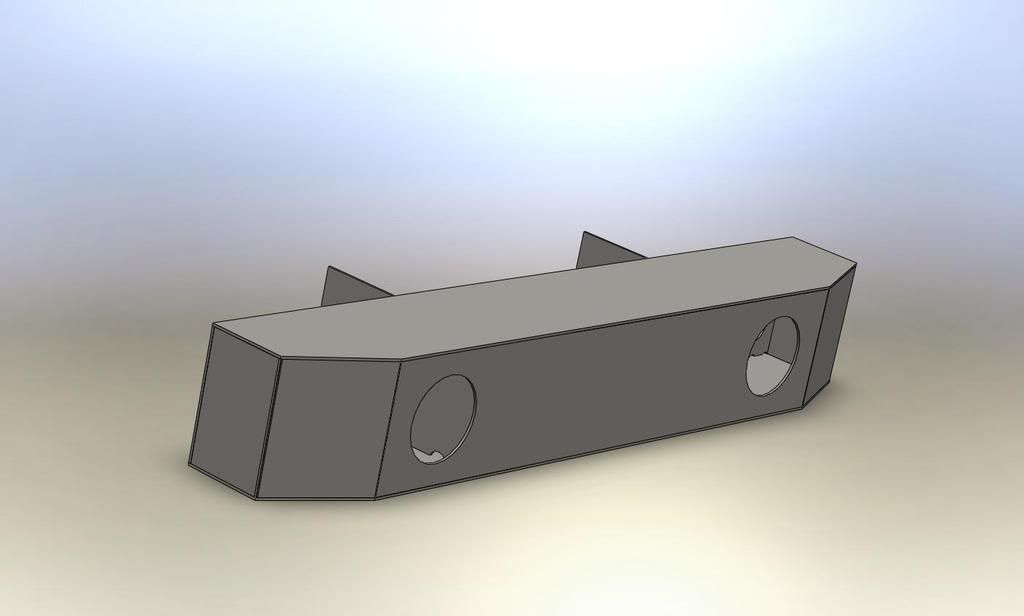
So I used SolidWorks to design the new rear bumper that I want to build. Attached is a picture of my model. I think some of the dimensions of the 4Runner need to be checked because a couple things don't look right, but mainly I just wanted to get an idea of how I wanted it to look. I think I'll use 3X4X3/16 sqr tubing for the main section, and then I'll build up the sides with 3/16" plate. I also think I'll put 1 1/2 x 1 1/2 x 1/4 sqr tubing on the bottom of the sides. Im going to attach the main section to the existing trailer hitch mounts. They are pretty beefy (1/2"). I'll have to cut them off though and drill new holes to mount to (right now you can see them sticking down below the bumper). I think I'll also mount the side sections to the frame.
Any suggestions from people that have built steel plate bumpers before? Has 3/16" worked well for others? I'll post pics as I begin to weld it up. I may want to add a spare tire carrier in the future, but for now I'll just do the bumper.
Also, has anyone else done any 2nd gen 4Runner modeling in SolidWorks or any other 3D modeling program? I would really like to get a hold of a more accurate 4Runner model.
 02-25-2008, 08:46 AM
#2
Contributing Member
nice work on the bumper so far, i just got done building my front bumper from a 3-D model (3rd gen). Each piece was modeled separately, so it made it real easy when it came to dimensioning each piece for cutting
I would say 3/16 is overkill for plating, unless it is structural... I used 10ga? or so, it was about 1/8" thick, and plenty.
If you are thinking about a tire carrier, best would be to plan ahead, you could spend a little time now designing/figuring it out, and save a lot of hassle later. If you had it all designed now, you could just wait until the rest is made, and be able to just bolt it up without a lot of hassle
02-25-2008, 09:12 AM
#3
Contributing Member
Thread Starter
Join Date: Jun 2006
Location: Bountiful, UT
Posts: 156
Likes: 0
Received 0 Likes
on
0 Posts
Indeed. I'll need to refine my 4runner before I add the tire carrier. So 1/8" plate is thick enough huh? That'll definitely be cheaper and lighter. I think I have an FEA program that came with pirated SolidWorks. Maybe I'll run it and see what kind of stresses I get. Determining what loads to apply is the big question though. Probably worst case off-road scenario will be a vertical load on the outside corner. Maybe assume half the weight of the vehicle plus some type of impact factor.
02-25-2008, 09:36 AM
#4
Contributing Member
lol, sorry, it's gonna take a lot more than that, and a lot more consideration to run an FEA to get any real worthwhile data...
If just used for side plates and such, 1/8 will be fine...
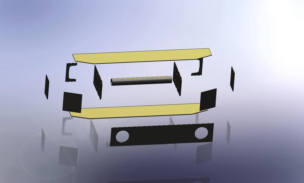
See enclosed picture, that is my front bumper, it is now completely built, so I'm not just making stuff up, i just don't have pictures of it at work... The dimensions of the steel i used are included, and it is definitely stronger than it needs to be
If just used for side plates and such, 1/8 will be fine...
See enclosed picture, that is my front bumper, it is now completely built, so I'm not just making stuff up, i just don't have pictures of it at work... The dimensions of the steel i used are included, and it is definitely stronger than it needs to be
02-25-2008, 09:45 AM
#6
Contributing Member
Thread Starter
Join Date: Jun 2006
Location: Bountiful, UT
Posts: 156
Likes: 0
Received 0 Likes
on
0 Posts
Why would I think your making stuff up? It would just be interesting to see some FEA analysis of bumpers using different steel thicknesses. Your probably right that .125 is plenty thick.
Props on the bumper model! You put some good work into that. Did you create 4Runner model too? That is really good. Do you do 3D modeling for your career? I just did some modeling in a few classes school and then I used it quite a bit on my Senior Design Project. We designed and built a "Mini Baja Vehicle" for the SAE Mini Baja West competition. It was pretty fun. I need more practice with the modeling though. I haven't done any for over a year and a half. I only use AutoCAD at work now. AutoCAD and SolidWorks feel totally opposite in the way you draw with them. Its frustrating to go back and forth between them.
Props on the bumper model! You put some good work into that. Did you create 4Runner model too? That is really good. Do you do 3D modeling for your career? I just did some modeling in a few classes school and then I used it quite a bit on my Senior Design Project. We designed and built a "Mini Baja Vehicle" for the SAE Mini Baja West competition. It was pretty fun. I need more practice with the modeling though. I haven't done any for over a year and a half. I only use AutoCAD at work now. AutoCAD and SolidWorks feel totally opposite in the way you draw with them. Its frustrating to go back and forth between them.
02-25-2008, 09:52 AM
#7
Registered User
Join Date: Feb 2007
Location: Sierra Nevada's or the Deserts of Las Vegas
Posts: 2,203
Likes: 0
Received 0 Likes
on
0 Posts
lol, sorry, it's gonna take a lot more than that, and a lot more consideration to run an FEA to get any real worthwhile data...
If just used for side plates and such, 1/8 will be fine...
See enclosed picture, that is my front bumper, it is now completely built, so I'm not just making stuff up, i just don't have pictures of it at work... The dimensions of the steel i used are included, and it is definitely stronger than it needs to be
Trending Topics
02-25-2008, 10:04 AM
#8
Contributing Member
Why would I think your making stuff up? It would just be interesting to see some FEA analysis of bumpers using different steel thicknesses. Your probably right that .125 is plenty thick.
Props on the bumper model! You put some good work into that. Did you create 4Runner model too? That is really good. Do you do 3D modeling for your career? I just did some modeling in a few classes school and then I used it quite a bit on my Senior Design Project. We designed and built a "Mini Baja Vehicle" for the SAE Mini Baja West competition. It was pretty fun. I need more practice with the modeling though. I haven't done any for over a year and a half. I only use AutoCAD at work now. AutoCAD and SolidWorks feel totally opposite in the way you draw with them. Its frustrating to go back and forth between them.
Props on the bumper model! You put some good work into that. Did you create 4Runner model too? That is really good. Do you do 3D modeling for your career? I just did some modeling in a few classes school and then I used it quite a bit on my Senior Design Project. We designed and built a "Mini Baja Vehicle" for the SAE Mini Baja West competition. It was pretty fun. I need more practice with the modeling though. I haven't done any for over a year and a half. I only use AutoCAD at work now. AutoCAD and SolidWorks feel totally opposite in the way you draw with them. Its frustrating to go back and forth between them.
All I modeled is what you see, too much work to do the rest since it is all solids, not just a surface. I'm an Mech Eng student, trying to focus on machine design. I get to use Inventor a little at work (similar to SolidWorks), besides an introductory class to NX3, most has been self-taught. AutoCAD versus 3D is completely different, additionally, IMO 3D in AutoCAD is completely useless and should be avoided
 02-25-2008, 10:49 AM
#9
Contributing Member
It might depend on your application. If you wheel hard, and plan for this bumper to be used hard... I'd bump up to 3/16". Especially in the areas of your pivot for a possible tire carrier.
My rear bumper is not a thing of beauty, but I was able to bend my 4" by 2" rectangular main tube very quickly once I got into the boulders IIRC, it was 1/8" wall, but may have even been 3/16".
Once I got things straightened out, I added some extensive 3/16 gussets on the interior of the corners. I suppose my design may have been lacking... but the rear bumper on a 4Runner takes a lot of abuse. Long overhang and good amount of weight can really test out a design. Pay special attention to the leverage the wings will place on your main crossmember. That was my over site, despite supporting the wings at their ends to the frame.
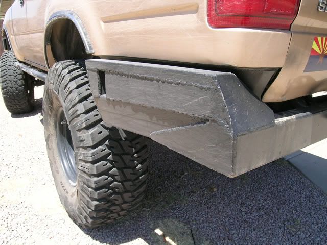
I can really come down on just about anything now with confidence. I have left a fair amount of metal all around AZ to prove it, although I don't exactley know what I am trying to prove.
My rear bumper is not a thing of beauty, but I was able to bend my 4" by 2" rectangular main tube very quickly once I got into the boulders IIRC, it was 1/8" wall, but may have even been 3/16".
Once I got things straightened out, I added some extensive 3/16 gussets on the interior of the corners. I suppose my design may have been lacking... but the rear bumper on a 4Runner takes a lot of abuse. Long overhang and good amount of weight can really test out a design. Pay special attention to the leverage the wings will place on your main crossmember. That was my over site, despite supporting the wings at their ends to the frame.
I can really come down on just about anything now with confidence. I have left a fair amount of metal all around AZ to prove it, although I don't exactley know what I am trying to prove.
02-25-2008, 10:55 AM
#10
Contributing Member
Mine is 2x2x.120 and it has a few dents, and it is bent from where I came down backwards on Kenny's Climb in Moab with no brakes. But that's the ENTIRE weight of the truck moving at >10 MPH, and it wasn't bent enough for me to worry about fixing...
I guess what I'm saying is you're better off with more bracing than you are with more wall thickness...
Here's some pix of my bumper (before the rear exo)


I guess what I'm saying is you're better off with more bracing than you are with more wall thickness...
Here's some pix of my bumper (before the rear exo)
02-25-2008, 11:00 AM
#11
Contributing Member
02-25-2008, 11:13 AM
#12
Contributing Member
Thread Starter
Join Date: Jun 2006
Location: Bountiful, UT
Posts: 156
Likes: 0
Received 0 Likes
on
0 Posts
Wow, came down Kenny's climb with no brakes. I wish you had video of that. I went through Fins & Things last spring and had a blast. If I remember right Kenny's was the long hill towards the end of the trail. What happened?
Last edited by WillRadford; 02-25-2008 at 11:14 AM.
02-25-2008, 11:27 AM
#13
Contributing Member
Thread Starter
Join Date: Jun 2006
Location: Bountiful, UT
Posts: 156
Likes: 0
Received 0 Likes
on
0 Posts
It might depend on your application. If you wheel hard, and plan for this bumper to be used hard... I'd bump up to 3/16". Especially in the areas of your pivot for a possible tire carrier.
My rear bumper is not a thing of beauty, but I was able to bend my 4" by 2" rectangular main tube very quickly once I got into the boulders IIRC, it was 1/8" wall, but may have even been 3/16".
Once I got things straightened out, I added some extensive 3/16 gussets on the interior of the corners. I suppose my design may have been lacking... but the rear bumper on a 4Runner takes a lot of abuse. Long overhang and good amount of weight can really test out a design. Pay special attention to the leverage the wings will place on your main crossmember. That was my over site, despite supporting the wings at their ends to the frame.
I can really come down on just about anything now with confidence. I have left a fair amount of metal all around AZ to prove it, although I don't exactley know what I am trying to prove.
Elvota: Dude, that thing is freaking stout! You could back off the Lion's Back iin Moab with that thing and it wouldn't dent. Nice work. I'd like to see someone rear end you on the road. It would mess their car up pretty good.
02-25-2008, 03:46 PM
#14
Contributing Member
Kenny's Climb is an optional "shortcut" where instead of going around you go straight up the side of the fin. Not real long, but steep as *%& and you're coming across the fin on the top, so you don't have much room for error on the turn.
It was raining (like alert Noah - seriously) and I was trying to see where to turn and go slow and stalled it. Without the power assist, the brakes were no match for the steepness and down I went.
I think there may be video (or at least pictures) somewhere...
It was raining (like alert Noah - seriously) and I was trying to see where to turn and go slow and stalled it. Without the power assist, the brakes were no match for the steepness and down I went.
I think there may be video (or at least pictures) somewhere...
06-25-2008, 10:18 AM
#15
Registered User

Join Date: Jun 2008
Posts: 3
Likes: 0
Received 0 Likes
on
0 Posts
Do you use Solidworks to generate DXFs for lasercutting? OR, do you just use Solidworks to generate a solid, get it looking how you want it, and then cut the steel to dimensions from a solidworks drawing?
I'm trying to build a bumper that's fairly complex and I want to have all the parts lasercut. What's the best approach to doing this in solidworks?
Thanks!
I'm trying to build a bumper that's fairly complex and I want to have all the parts lasercut. What's the best approach to doing this in solidworks?
Thanks!
06-25-2008, 11:25 AM
#16
Contributing Member
Thread Starter
Join Date: Jun 2006
Location: Bountiful, UT
Posts: 156
Likes: 0
Received 0 Likes
on
0 Posts
Do you use Solidworks to generate DXFs for lasercutting? OR, do you just use Solidworks to generate a solid, get it looking how you want it, and then cut the steel to dimensions from a solidworks drawing?
I'm trying to build a bumper that's fairly complex and I want to have all the parts lasercut. What's the best approach to doing this in solidworks?
Thanks!
I'm trying to build a bumper that's fairly complex and I want to have all the parts lasercut. What's the best approach to doing this in solidworks?
Thanks!
Sorry, I don't know about generating DXF files from SolidWorks.
06-25-2008, 12:02 PM
#17
Registered User
Join Date: Jun 2008
Posts: 3
Likes: 0
Received 0 Likes
on
0 Posts
"But, now that Im to the point of welding it on, Im realizing that my 4runner model was not accurate enough and Im having to modify a few of my pieces to make it fit and look good."
Yep, that's my concern! I know Solidworks and such programs have the ability to rip a solid model apart, but i'm having a hard time figuring out which commands to use.
It's one thing to make a cool looking solid model in SW. It's another thing to build it physically!
Ideally I'd be able to send a DXF file to the steel cutters, and get back a load of lasercut bumper puzzle pieces. Then it's just a bunch of tack welding, hopefully not much grinding, then lay down some solid welds, grind, paint!
But how to unlock the power...
I have tried building new parts in an assembly. Insert component>new part.
This lets you open a sketch on one plate of the bumper at a time, and extrude, loft, etc. to the next plate. Just like how you'd build it if you had all the pieces in front of you.
I think this isn't the fastest way, though.
06-25-2008, 12:17 PM
#18
Contributing Member
Thread Starter
Join Date: Jun 2006
Location: Bountiful, UT
Posts: 156
Likes: 0
Received 0 Likes
on
0 Posts
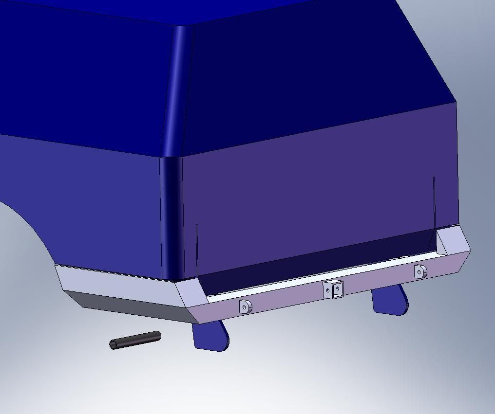
That is an updated pic of my model.
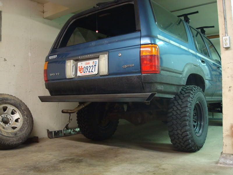
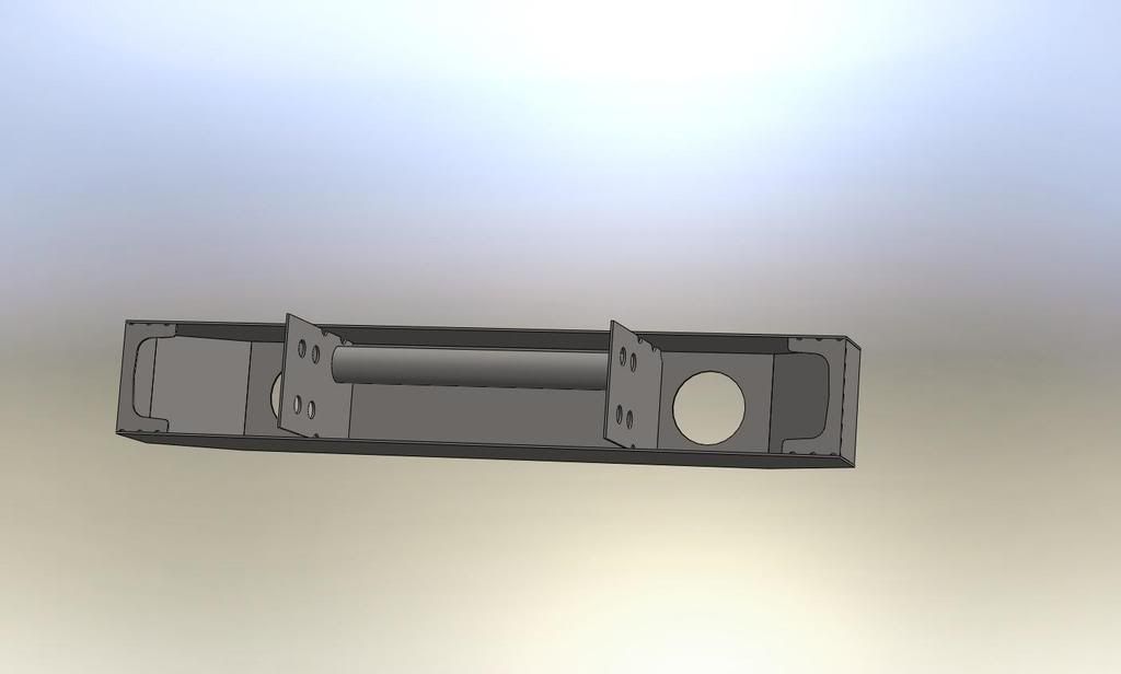
This is a pic of my progress so far. As you can tell Im not exactly cruising too quickly on this project. About the only time I have to work on it is after the 4 month old baby boy goes to sleep around 9:00 PM once in a while.
Do you already have yours drawn up? I'd like to see it when you do. I drew my bumper as one part and then made an assembly with the 4runner. Are you doing front or rear? I think a front bumper like WJWERDNA did would be harder than a rear, both modeling and fabricating.
07-01-2008, 03:45 PM
#19
Registered User
Join Date: Jun 2008
Posts: 3
Likes: 0
Received 0 Likes
on
0 Posts
I have an idea loosely drawn up.
I'm trying to make it so I can have all the pieces lasercut, then just weld them together. I'll have to fill the corners with weld, and grind.
The overall concept isn't my issue right now, so much as just trying to figure out how to make it in pieces so I can tack it together with minimal effort.
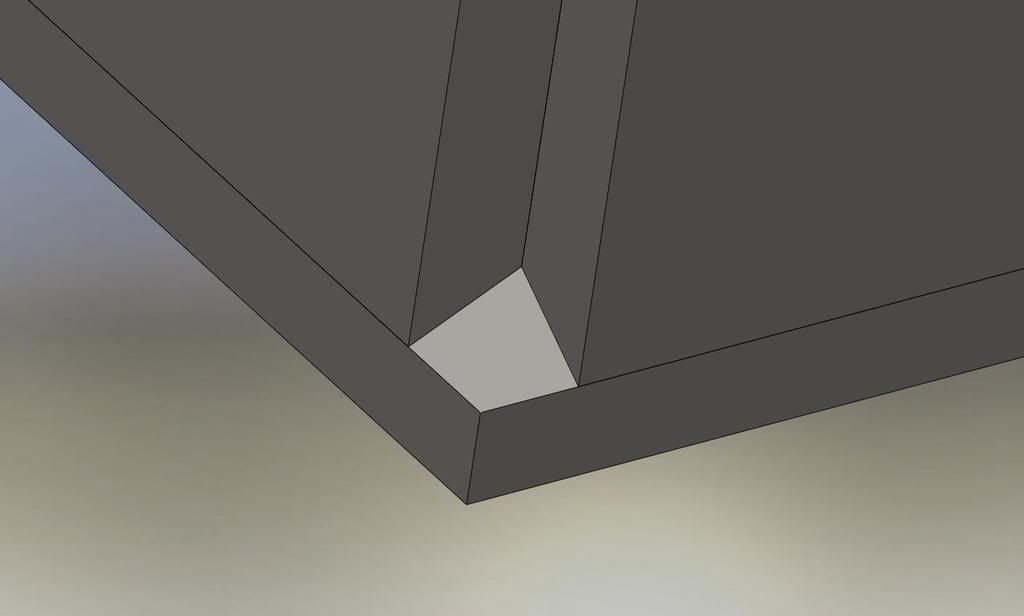
I'm trying to make it so I can have all the pieces lasercut, then just weld them together. I'll have to fill the corners with weld, and grind.
The overall concept isn't my issue right now, so much as just trying to figure out how to make it in pieces so I can tack it together with minimal effort.
07-01-2008, 06:55 PM
#20
Contributing Member
Thread Starter
Join Date: Jun 2006
Location: Bountiful, UT
Posts: 156
Likes: 0
Received 0 Likes
on
0 Posts
Nice, looks like that should work. You should ask WJWERDNA (he posted at the top of this thread) if you can have his model of the front end of a 4runner so you can see how it looks on the vehicle. Are you putting this on a 4runner? What year?


