Auto dimming mirror/compass/temp in Gen 3 Part II
 10-08-2007, 11:54 AM
#1
Auto dimming mirror/compass/temp in Gen 3 Part II
Well I finally got it done and working correctly. Didn't wish to post this and not have it functioning, so here it is!
For those of you who did not see the first part here is the link so you can get caught up on this install. https://www.yotatech.com/forums/f2/a...roject-125153/
As I mentioned, I found this mirror in my local wrecking yard. It is a Gentex GTNX 177 with compass and temperature display along with auto dimming feature. It came out of a 1999 GMC Surburban.
We left off with the new mirror assembled and installed on the button mount on the windshield. The next thing to accomplish is to route the harness from the mirror along the headliner and down the drivers side A-pillar. First thing you will need to accomplish is the removal of the Drivers side grab handle, sometimes referred to as the "OH S**T" handle.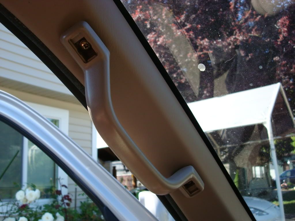
Remove the small covers over the two hold down screws at either end of the handle and using a large phillips remove those screws.
NOTE: If you have never pulled these screws, you will need an impact screwdriver and ball pean hammer to break these screws loose otherwise you will strip the heads of the screws!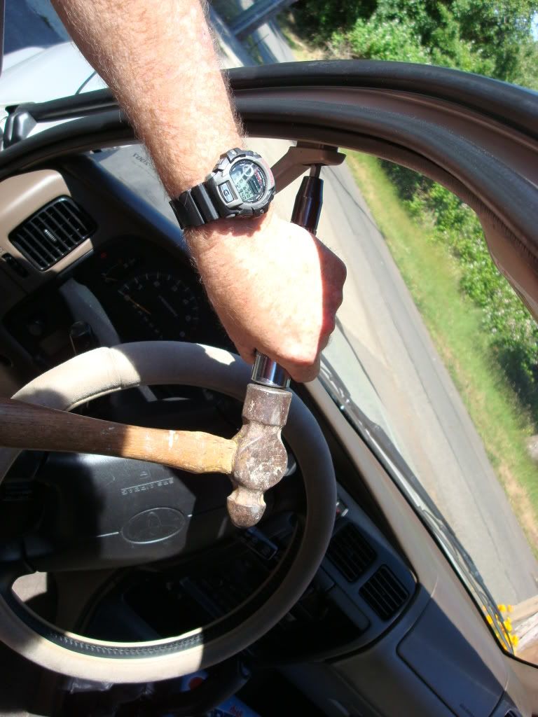
Getting around the steering wheel requires some assistance to remove the lower screw as I needed to use the impact, a 12"punch and the hammer routed through the spokes of the steering wheel.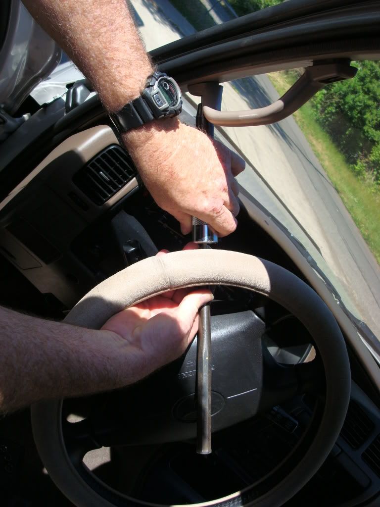
Once the screws are removed the cover will come off very easily with just grabbing the edges and pulling it off.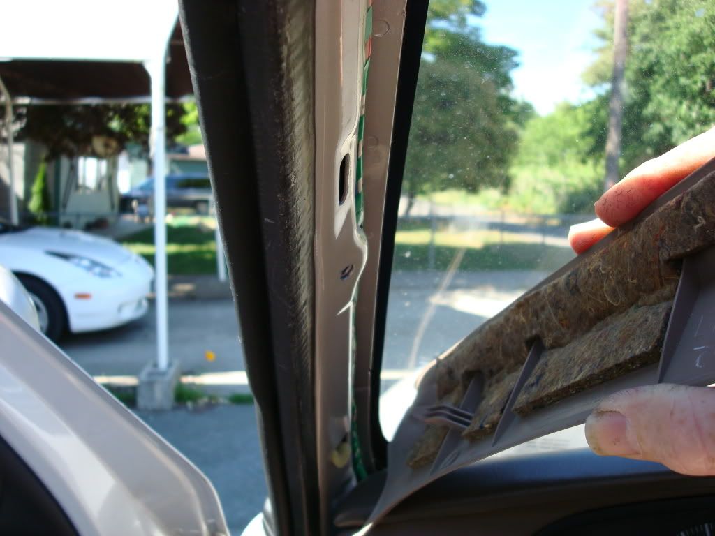
Remove the drivers side sun visor by removing the two phillips screws holding it in place.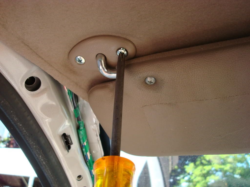
You can either thread the wire by hand but I recommend using a wire coat hanger.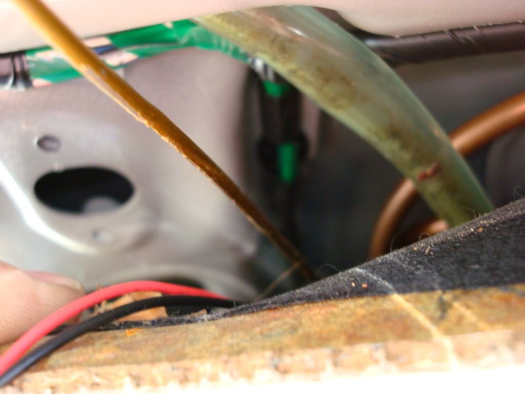
I removed the wires from the connector at the end of the harness (not the one that connects to the mirror) so that I had 7 wires to deal with. Two pink, brown, black, gray, green and green/black. Here is the pin/color layout for this mirror:
Pin 1 - Pink: 12vdc+
Pin 2 - Black: Ground -
Pin 3 - Green: Reverse sensor
Pin 4 - Grey: Not used
Pin 5 - Pink: Not used
Pin 6 - Green/Black: Temp sensor
Pin 7 - Brown: Temp sensor
Route the hanger through the roof and headliner to the mirror attachment point. Tape the end of the harness to the hanger and draw it back towards the drivers door. Make sure you have the ends taped over so they do not snag the roof support and framing. Pull the slack out leaving the connector end at the mirror side with about 2-3 inches of harness.
Next we will route the harness along the A-pillar using nylon wire ties to hold it in place with the installed wire bundle. First you will need to route the hanger wire from under the dash up to the base of the A-pillar, attach the wires and pull them down through the dash down to the drivers side Junction Box (J/B). This is referred to in wiring diagrams as the Intergration Relay.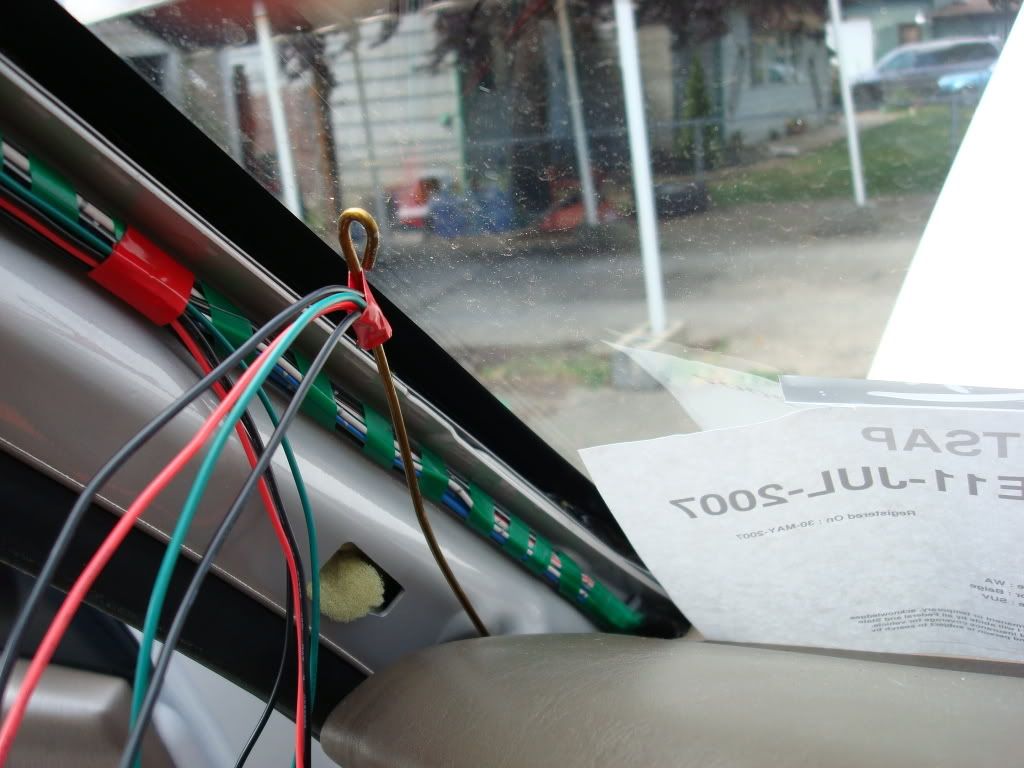
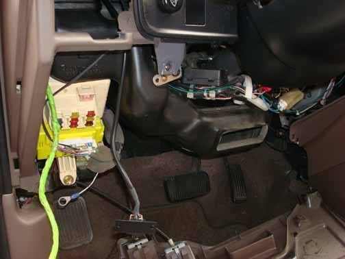
The J/B is located behind the lower drivers side dash cover near the left side kick panel.
Pull the slack out of the harness and you will have 7 wires.
You will need to seperate out the green/black and brown wires from the harness bundle. These will need to be routed through the firewall to the external sensor. This will leave you with two pink wires, one is primary power to the mirror. The other is for sensing power to the side mirrors which in the case of the Gen 3 we do not have. The remaining wires are pink, black, gray and green.

The mirror wiring diagram shows that the solid green is for the reverse switch sensing. This is so that when the mirror is active and you place the vehicle in reverse the mirror automatically un-dims so you can see better out the rear view mirror. But I had an issue when I attached it to my backup light wire to allow this feature. The first time I put the truck in reverse, I blew the 10A Gauges fuse which killed the power windows, moon roof, gauges, heater blower and backup lights. I did this during the day so I never noticed the issue until I got home and could not roll up my window. In my trouble shooting of the problem, I read in an article in another forum that if the GREEN reverse wire is not used to sense reverse being active then it should be connected to chassis ground to prevent improper operation of the mirror. I did this very thing after removing it from the reverse wire.
Black of course, went to chassis ground. The pink wire that is Pin 1 on the mirror is the pink wire we use for mirror input power. The second pink and grey wires will not be used.
First, I used some shrink wrap and covered the exposed metal of the pin leaving about 1/4 inch exposed.

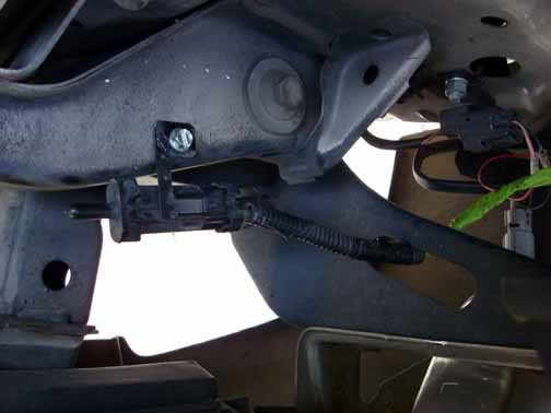
Next I located a 12vdc source that was positive when the ignition was switched on. It is located on the J/B at the connector as shown:

There are three wires on the edge of the connector as shown in the picture, Black, Grey and Blue. I pressed the tab end into the connector for the grey wire (middle wire of the 3). I then used a nylon wire tie to hold the connector in place so that it would not wiggle free during operation of the vehicle.
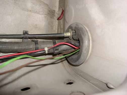
Route the sensor wires through the firewall as follows: From inside the engine compartment you will note on the drivers side at the firewall is a large rubber boot about 6-8 inches from the top of the hood. This will be our routing path.
I then chose to route the wire along the wire run above the fender and out to the front of the engine compartment exiting near the left headlight. You now need to locate and mount the temperature sensor. I chose to mount mine near the FMU sensor on the radiator framing. This image is looking down from the top of the radiator framing sensor.
Replace the J/B into its location using the two removed 10 mm bolts. I used the lower bolt as my ground attachment point. Ensure the mirror connector is properly inserted into the mirror, turn on the ignition and test for operation.
For those of you who did not see the first part here is the link so you can get caught up on this install. https://www.yotatech.com/forums/f2/a...roject-125153/
As I mentioned, I found this mirror in my local wrecking yard. It is a Gentex GTNX 177 with compass and temperature display along with auto dimming feature. It came out of a 1999 GMC Surburban.
We left off with the new mirror assembled and installed on the button mount on the windshield. The next thing to accomplish is to route the harness from the mirror along the headliner and down the drivers side A-pillar. First thing you will need to accomplish is the removal of the Drivers side grab handle, sometimes referred to as the "OH S**T" handle.
Remove the small covers over the two hold down screws at either end of the handle and using a large phillips remove those screws.
NOTE: If you have never pulled these screws, you will need an impact screwdriver and ball pean hammer to break these screws loose otherwise you will strip the heads of the screws!
Getting around the steering wheel requires some assistance to remove the lower screw as I needed to use the impact, a 12"punch and the hammer routed through the spokes of the steering wheel.
Once the screws are removed the cover will come off very easily with just grabbing the edges and pulling it off.
Remove the drivers side sun visor by removing the two phillips screws holding it in place.
You can either thread the wire by hand but I recommend using a wire coat hanger.
I removed the wires from the connector at the end of the harness (not the one that connects to the mirror) so that I had 7 wires to deal with. Two pink, brown, black, gray, green and green/black. Here is the pin/color layout for this mirror:
Pin 1 - Pink: 12vdc+
Pin 2 - Black: Ground -
Pin 3 - Green: Reverse sensor
Pin 4 - Grey: Not used
Pin 5 - Pink: Not used
Pin 6 - Green/Black: Temp sensor
Pin 7 - Brown: Temp sensor
Route the hanger through the roof and headliner to the mirror attachment point. Tape the end of the harness to the hanger and draw it back towards the drivers door. Make sure you have the ends taped over so they do not snag the roof support and framing. Pull the slack out leaving the connector end at the mirror side with about 2-3 inches of harness.
Next we will route the harness along the A-pillar using nylon wire ties to hold it in place with the installed wire bundle. First you will need to route the hanger wire from under the dash up to the base of the A-pillar, attach the wires and pull them down through the dash down to the drivers side Junction Box (J/B). This is referred to in wiring diagrams as the Intergration Relay.
The J/B is located behind the lower drivers side dash cover near the left side kick panel.
Pull the slack out of the harness and you will have 7 wires.
You will need to seperate out the green/black and brown wires from the harness bundle. These will need to be routed through the firewall to the external sensor. This will leave you with two pink wires, one is primary power to the mirror. The other is for sensing power to the side mirrors which in the case of the Gen 3 we do not have. The remaining wires are pink, black, gray and green.
The mirror wiring diagram shows that the solid green is for the reverse switch sensing. This is so that when the mirror is active and you place the vehicle in reverse the mirror automatically un-dims so you can see better out the rear view mirror. But I had an issue when I attached it to my backup light wire to allow this feature. The first time I put the truck in reverse, I blew the 10A Gauges fuse which killed the power windows, moon roof, gauges, heater blower and backup lights. I did this during the day so I never noticed the issue until I got home and could not roll up my window. In my trouble shooting of the problem, I read in an article in another forum that if the GREEN reverse wire is not used to sense reverse being active then it should be connected to chassis ground to prevent improper operation of the mirror. I did this very thing after removing it from the reverse wire.
Black of course, went to chassis ground. The pink wire that is Pin 1 on the mirror is the pink wire we use for mirror input power. The second pink and grey wires will not be used.
First, I used some shrink wrap and covered the exposed metal of the pin leaving about 1/4 inch exposed.
Next I located a 12vdc source that was positive when the ignition was switched on. It is located on the J/B at the connector as shown:
There are three wires on the edge of the connector as shown in the picture, Black, Grey and Blue. I pressed the tab end into the connector for the grey wire (middle wire of the 3). I then used a nylon wire tie to hold the connector in place so that it would not wiggle free during operation of the vehicle.
Route the sensor wires through the firewall as follows: From inside the engine compartment you will note on the drivers side at the firewall is a large rubber boot about 6-8 inches from the top of the hood. This will be our routing path.
I then chose to route the wire along the wire run above the fender and out to the front of the engine compartment exiting near the left headlight. You now need to locate and mount the temperature sensor. I chose to mount mine near the FMU sensor on the radiator framing. This image is looking down from the top of the radiator framing sensor.
Replace the J/B into its location using the two removed 10 mm bolts. I used the lower bolt as my ground attachment point. Ensure the mirror connector is properly inserted into the mirror, turn on the ignition and test for operation.


Thread
Thread Starter
Forum
Replies
Last Post
RedRunner_87
95.5-2004 Tacomas & 96-2002 4Runners (Build-Up Section)
84
06-01-2021 01:51 PM
Steezy96yota
86-95 Trucks & 4Runners (Build-Up Section)
1
07-06-2015 10:00 AM
FS[SouthEast]: 1st Gen 4Runner Slider Window, Driver Side
coryc85
Misc Stuff (Vehicle Related)
0
07-06-2015 04:07 AM


