duckhead's 91 pickup teardown and rebuild
 07-09-2016, 07:15 PM
#81
Registered User
Thread Starter

Join Date: Jun 2015
Location: WI
Posts: 147
Likes: 0
Received 0 Likes
on
0 Posts
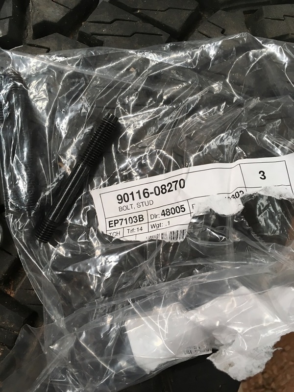
Parts came in and I picked them up on Thursday. Studs were wrong so I got those today.
Outlet tube - 16331-62040
gasket - 16341-62040
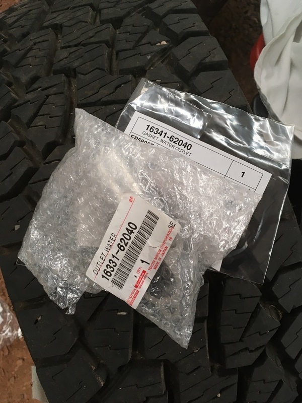
Pic of the Chinese made coolant gasket versus genuine Toyota for comparison. Chinese gasket is a bit misleading due to the angle. Didn't notice it until now...
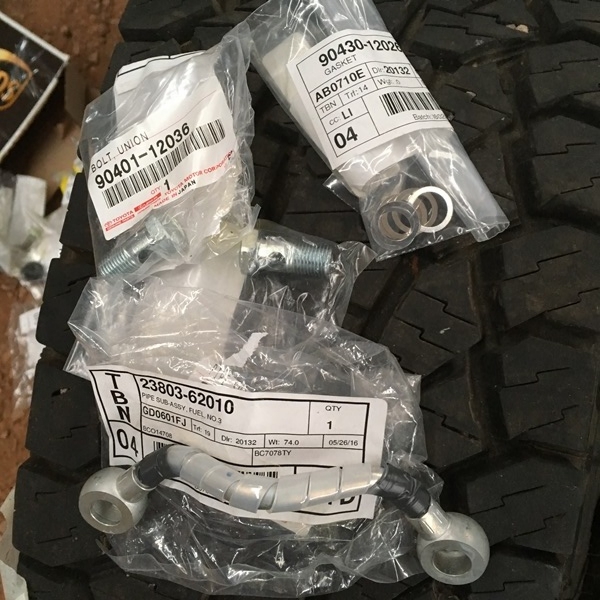
I also got new fuel union bolts for the rails. Not really necessary but if dismantling I would replace the gaskets. I bent the jumper fuel line so got one of those too.
Union bolt - 90401-12036
Gaskets - 90430-12028
Fuel jumper - 23803-62010
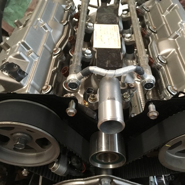
Front shot with all installed
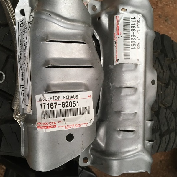
The heat shields on the donor were spent. One was completely missing and the other was rusted out.
Manifold heat shield - 17168-62051
- 17167-62051
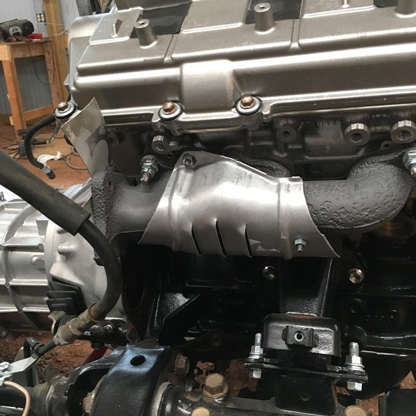
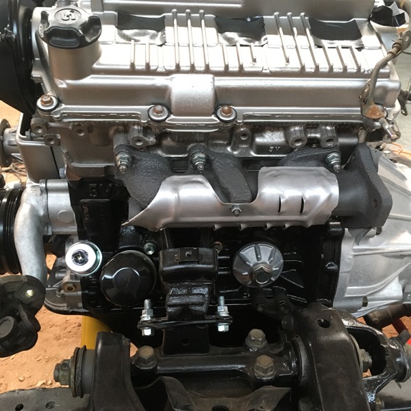
Installed...
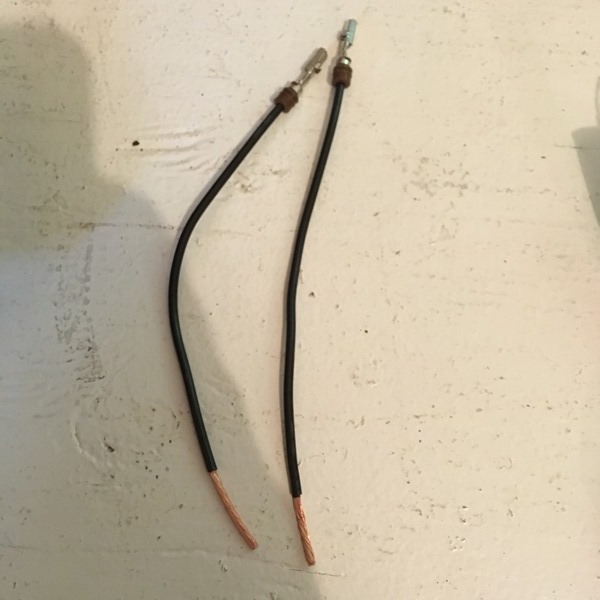
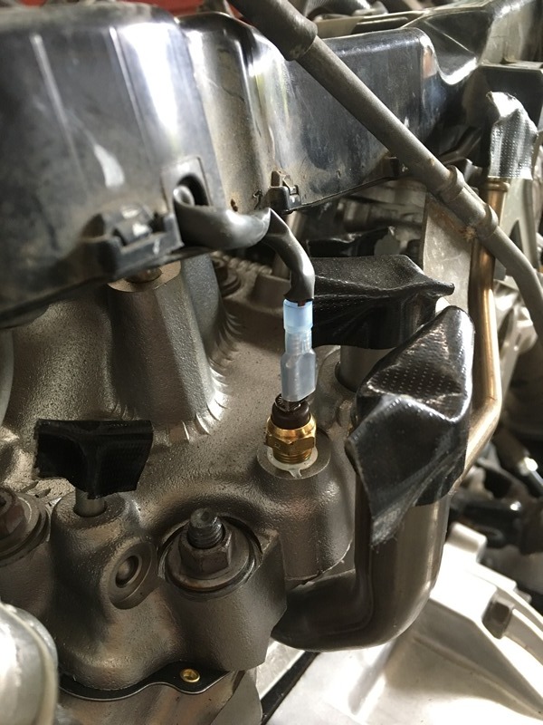
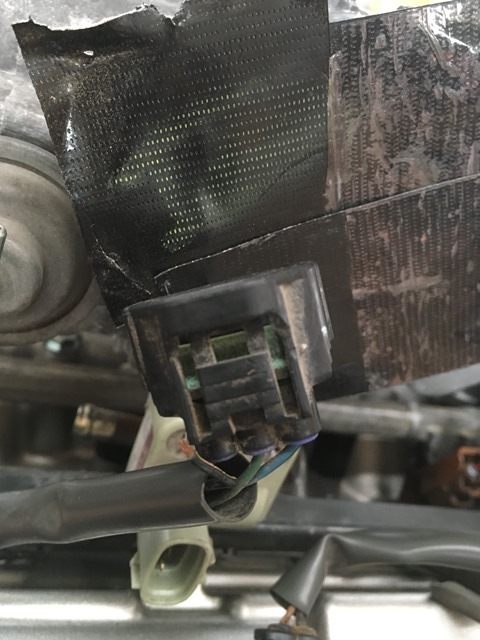
I traced down those connectors/wires that were damaged from the salvage yard. #1 from the previous post was a 2 wire plug and that went to a positioning sensor by the oil pressure sender. #2 was for the air conditioning and I don't have AC so this will get taped up and unused. #3 was not a ground. This was for the gauge temperature at the rear of the intake manifold.
If you have a plug like #1 ever get pulled I think your best served buying the pins and splicing. I don't think it would be possible to decrimp and recrimp but who knows... Admittedly I didn't do a good job documenting this process.
Replacement tips - 82998-12440
Unclip the white retainer clip and it should pop up and pull out.
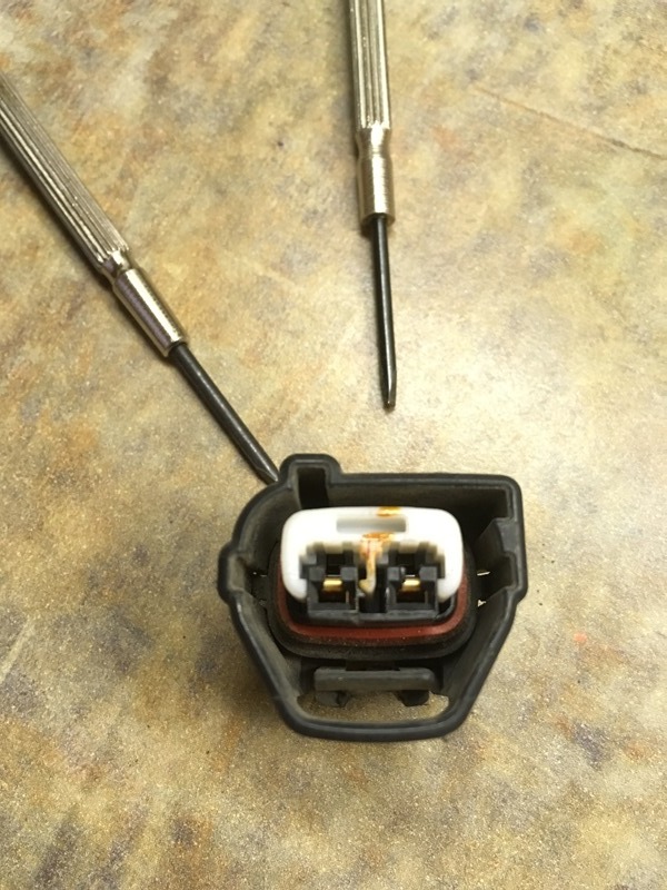
I think there's some clips on the sides to pull someting out too.
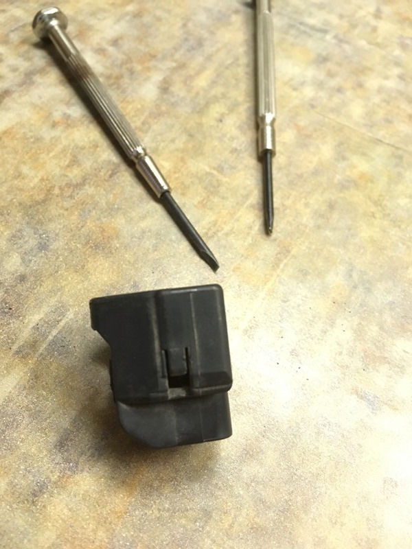
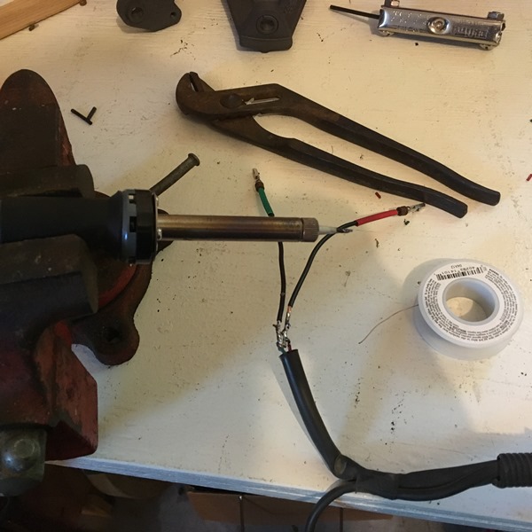
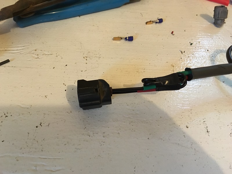
Jeweler's flatheads help to pull the connectors out. Lift a black tab up and then take another to push it out the rear. Once that happns take the new one; strip, splice, solder and shrink tube. I put smaller shrinktube on the leads so I know which color is what. Then I took larger diameter to actually shrink over the soldered wires. I left the original length the same so it would have been a bit long. I folded it on itself but made sure no bends at the soldered joints. Then loomed it.
Coolant pipe is just seated to plug the hole. Fixed version comes up later... But here's the plug in its rightful place
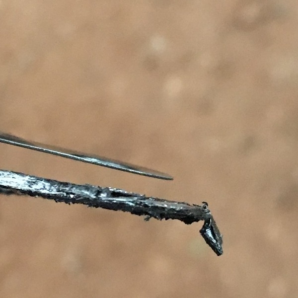
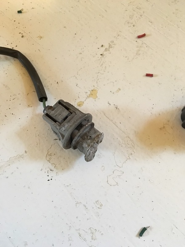
As a side note I thought this was funny.... Instead of removing the oil sender from the harness the salvage yard just snapped it off
#3 I used a standard connector. I think it was a 16-18 gauge connector but a smaller one would have likely worked.
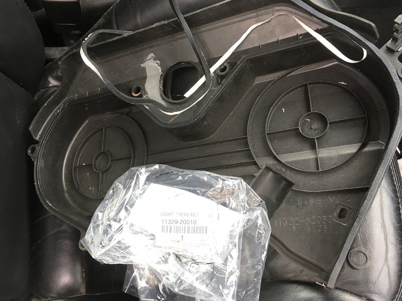
The timing cover on my replacement from Denny never came with a gasket. I bought one OEM
Gasket - 11329-20010
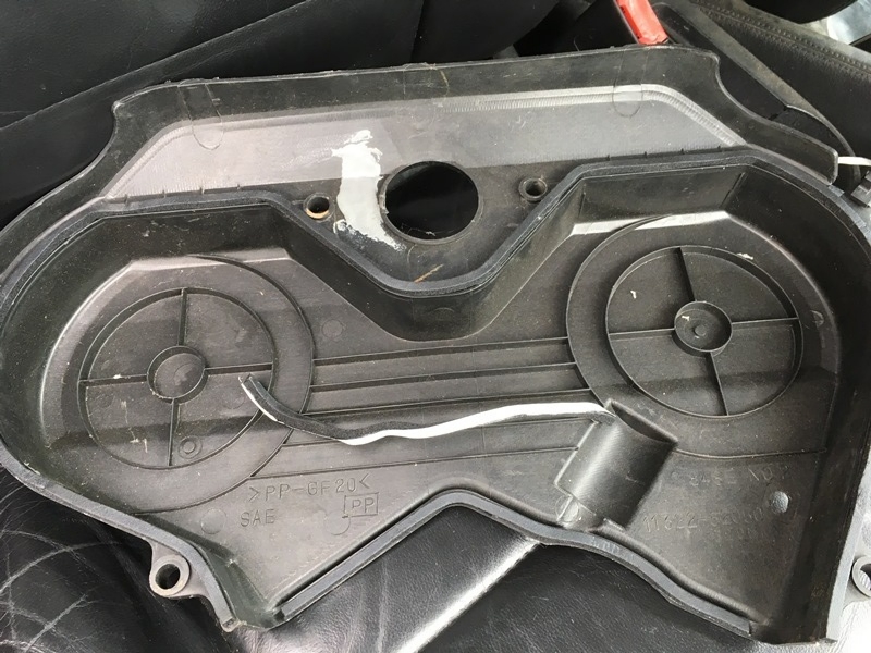
Rubbing alcohol around the cover. Peel the bottom and adhere as you go. I didn't worry about pressing hard to get it fully seated. I bolted it up to engine to get that going.
This is how much is left over after doing top and bottom
and on
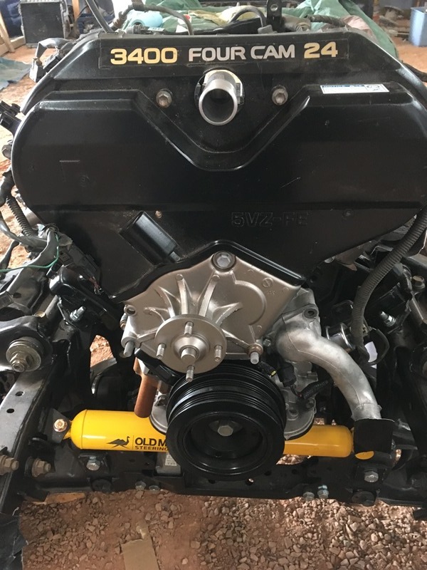
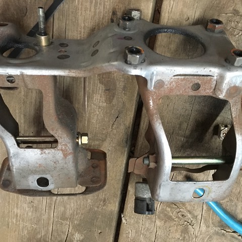
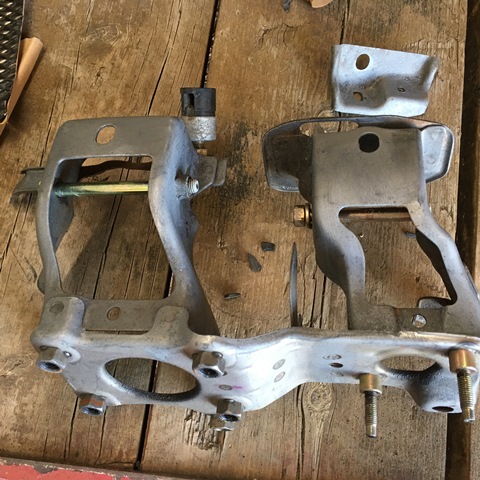
I also painted and baked the mounts for the power steering and alternator with the POR15 hi-temp paint. They were pretty rusted and I don't know what other paint would have worked within that proximity of the exhaust manifolds.
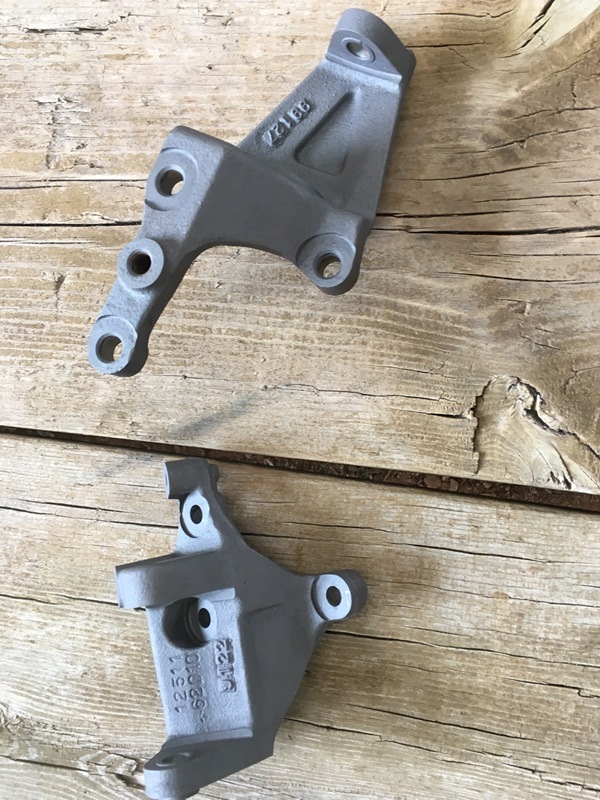
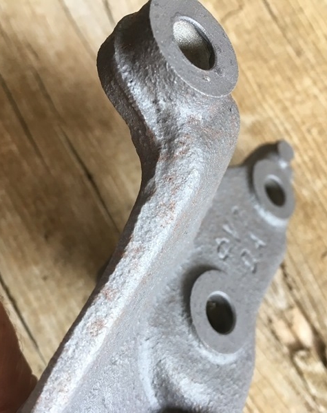
Be interesting to see how long this paint holds up. It *looks* like some rust is chewing through the mount but we'll see what happens... Look at the left most part of the mount
Bolted em up and then I splurged with an OEM power steering pump.
Pump - 44320-35490
Put it on with the donor vehicle pulley. Blasted it and then painted.
Bought this lot from Rockauto. The donor vehicle did have an error code on the plug so I was concerned with the coils. These removed any doubt I bought the 99-00 4runner fan clutch because it was cheaper than the 1991.
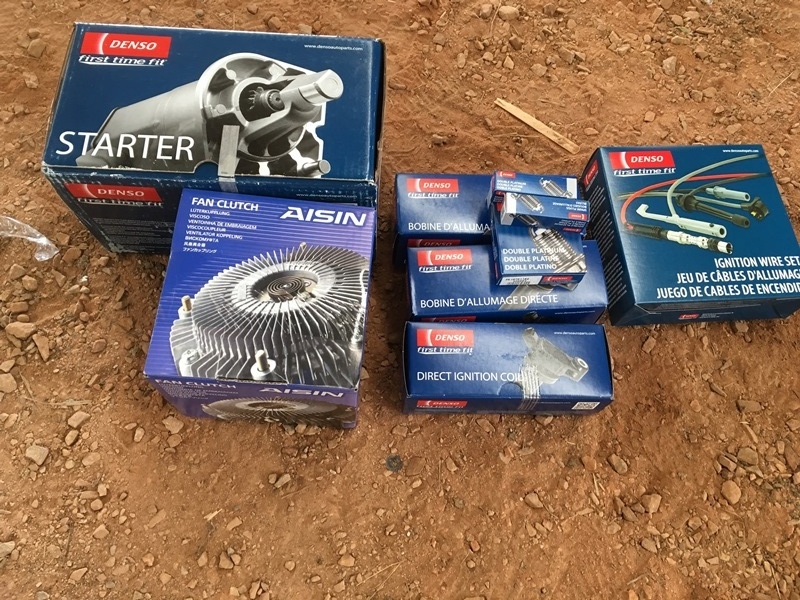
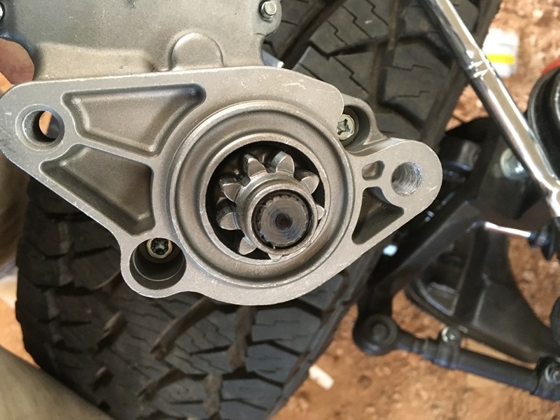
I went with the 99 starter and as the story goes, gotta drill out one of the bolt holes on the starter.
Here's the lot installed. Can't really see the starter... Gotta pull the plug wire "organizer clips" from donor vehicle...
Studs are in and I lucked out!!! I just had to tap the hole... No need to spend the money on a helicoil kit
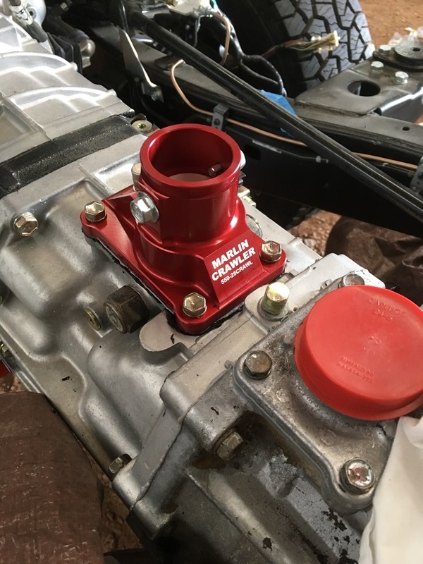
I decided on the short throw shifter from Marlin Crawler over the winter after I already got the transmission otherwise they would have installed it for me. Here's the OEM housing they put on.
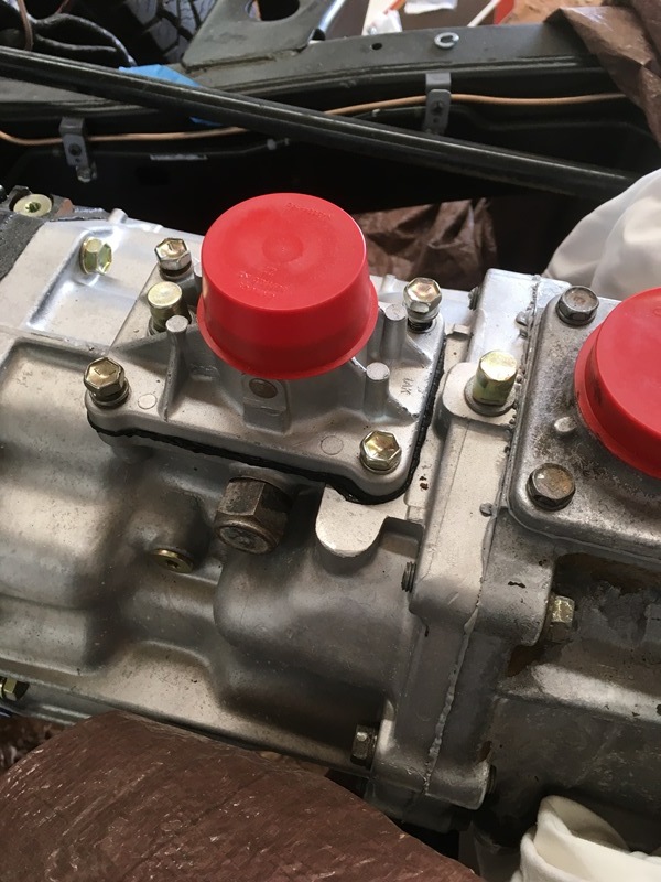
I left the oil slinger on. It was brand new. I thought the marlin rep said the new design doesn't require it but what the hell... couldn't hurt right? Their instructions on the web still state to use it.
Now left with this.....
Outlet tube - 16331-62040
gasket - 16341-62040

Pic of the Chinese made coolant gasket versus genuine Toyota for comparison. Chinese gasket is a bit misleading due to the angle. Didn't notice it until now...

I also got new fuel union bolts for the rails. Not really necessary but if dismantling I would replace the gaskets. I bent the jumper fuel line so got one of those too.
Union bolt - 90401-12036
Gaskets - 90430-12028
Fuel jumper - 23803-62010

Front shot with all installed

The heat shields on the donor were spent. One was completely missing and the other was rusted out.
Manifold heat shield - 17168-62051
- 17167-62051

Installed...


I traced down those connectors/wires that were damaged from the salvage yard. #1 from the previous post was a 2 wire plug and that went to a positioning sensor by the oil pressure sender. #2 was for the air conditioning and I don't have AC so this will get taped up and unused. #3 was not a ground. This was for the gauge temperature at the rear of the intake manifold.
If you have a plug like #1 ever get pulled I think your best served buying the pins and splicing. I don't think it would be possible to decrimp and recrimp but who knows... Admittedly I didn't do a good job documenting this process.
Replacement tips - 82998-12440

Unclip the white retainer clip and it should pop up and pull out.

I think there's some clips on the sides to pull someting out too.

Jeweler's flatheads help to pull the connectors out. Lift a black tab up and then take another to push it out the rear. Once that happns take the new one; strip, splice, solder and shrink tube. I put smaller shrinktube on the leads so I know which color is what. Then I took larger diameter to actually shrink over the soldered wires. I left the original length the same so it would have been a bit long. I folded it on itself but made sure no bends at the soldered joints. Then loomed it.


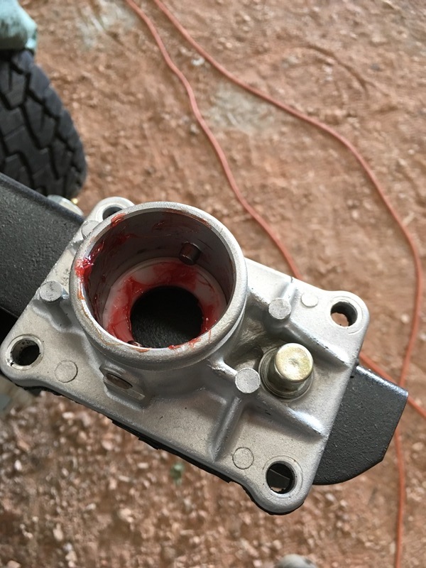
Coolant pipe is just seated to plug the hole. Fixed version comes up later... But here's the plug in its rightful place

As a side note I thought this was funny.... Instead of removing the oil sender from the harness the salvage yard just snapped it off

#3 I used a standard connector. I think it was a 16-18 gauge connector but a smaller one would have likely worked.


The timing cover on my replacement from Denny never came with a gasket. I bought one OEM
Gasket - 11329-20010
Rubbing alcohol around the cover. Peel the bottom and adhere as you go. I didn't worry about pressing hard to get it fully seated. I bolted it up to engine to get that going.

This is how much is left over after doing top and bottom

and on

I also painted and baked the mounts for the power steering and alternator with the POR15 hi-temp paint. They were pretty rusted and I don't know what other paint would have worked within that proximity of the exhaust manifolds.

Be interesting to see how long this paint holds up. It *looks* like some rust is chewing through the mount but we'll see what happens... Look at the left most part of the mount

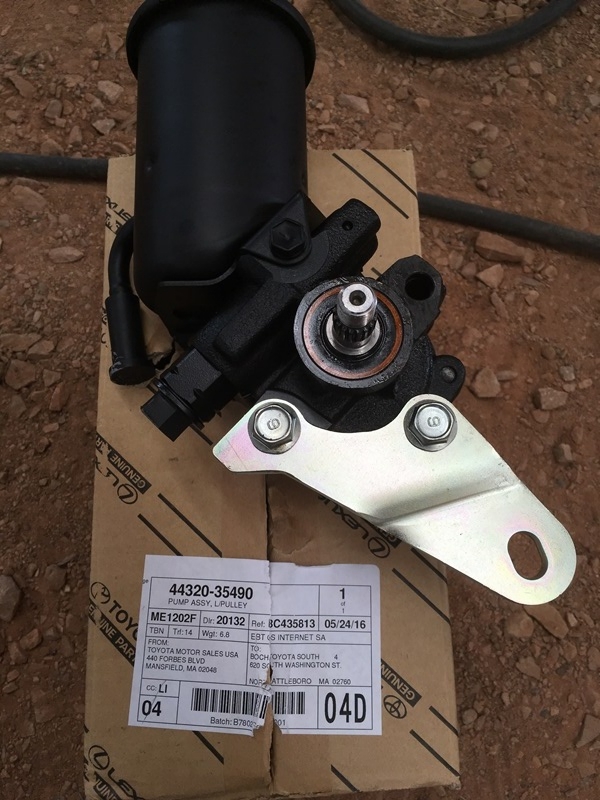
Bolted em up and then I splurged with an OEM power steering pump.
Pump - 44320-35490

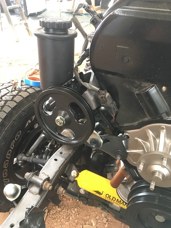
Put it on with the donor vehicle pulley. Blasted it and then painted.

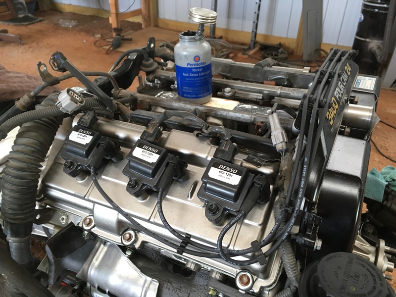
Bought this lot from Rockauto. The donor vehicle did have an error code on the plug so I was concerned with the coils. These removed any doubt
I bought the 99-00 4runner fan clutch because it was cheaper than the 1991.
I went with the 99 starter and as the story goes, gotta drill out one of the bolt holes on the starter.

Here's the lot installed. Can't really see the starter... Gotta pull the plug wire "organizer clips" from donor vehicle...

Studs are in and I lucked out!!! I just had to tap the hole... No need to spend the money on a helicoil kit


I decided on the short throw shifter from Marlin Crawler over the winter after I already got the transmission otherwise they would have installed it for me. Here's the OEM housing they put on.

I left the oil slinger on. It was brand new. I thought the marlin rep said the new design doesn't require it but what the hell... couldn't hurt right? Their instructions on the web still state to use it.

Now left with this.....

Last edited by duckhead; 07-10-2016 at 03:36 AM.
 07-10-2016, 07:34 AM
#82
Registered User
Thread Starter
Join Date: Jun 2015
Location: WI
Posts: 147
Likes: 0
Received 0 Likes
on
0 Posts
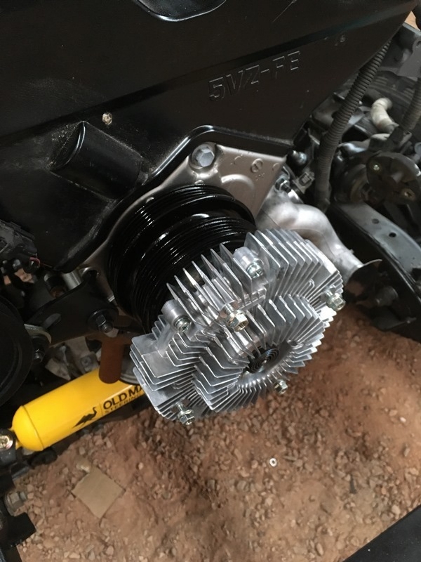
Got a few minutes in this morning. I forgot about the 2 pulley's behind the fan clutch from the donor vehicle so I blasted and painted em yesterday afternoon with rattle can enamel. Put em in along with the fan clutch...
Dropped in the oil tube and dipstick as well. As a sidenote, convenient an oil cooler wasn't put in. Not that I'm opposed, just don't feel it's really necessary up here. Plus it removes some clutter Should have been obvious from previous pics but just highlighting it now.
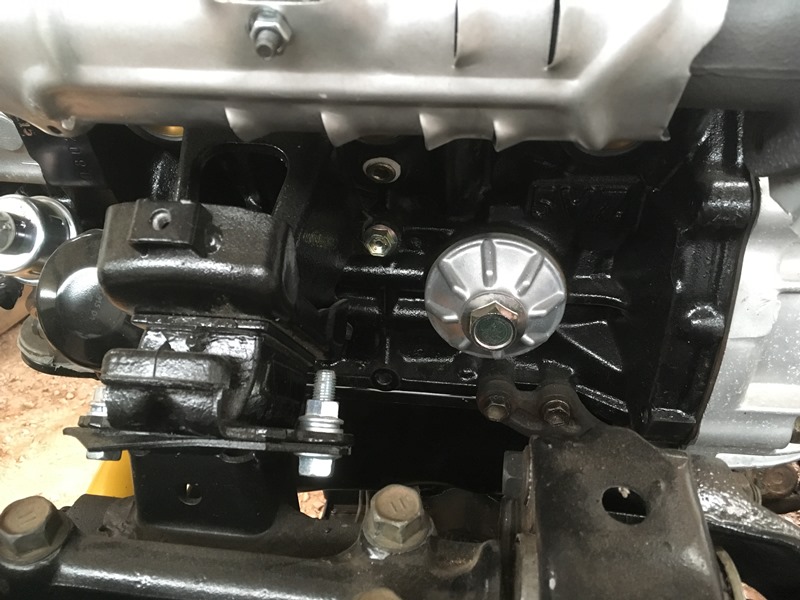
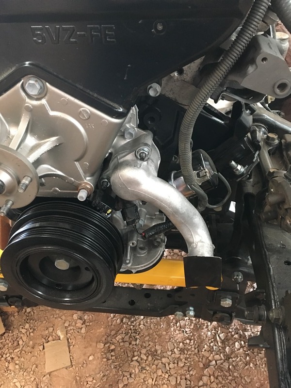
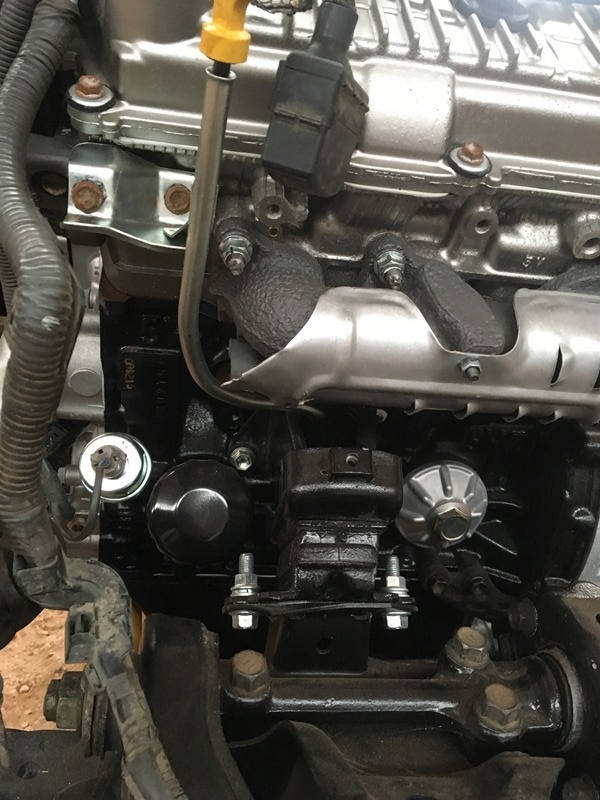
And here's the tube installed... Routes the same as the 3.0 between the frame mounts and up. Difference is there's 2 bolts on the alternator bracket itself that it fastens up to.
For those curious on part numbers. Sticky in the 3.4 thread will explain everything I made sure Denny knew which was supposed to go into the motor during the build and he made it happen.
https://www.yotatech.com/forums/f160...l-swap-237832/

Dropped in the oil tube and dipstick as well. As a sidenote, convenient an oil cooler wasn't put in. Not that I'm opposed, just don't feel it's really necessary up here. Plus it removes some clutter
Should have been obvious from previous pics but just highlighting it now. 
And here's the tube installed... Routes the same as the 3.0 between the frame mounts and up. Difference is there's 2 bolts on the alternator bracket itself that it fastens up to.

For those curious on part numbers. Sticky in the 3.4 thread will explain everything
I made sure Denny knew which was supposed to go into the motor during the build and he made it happen.https://www.yotatech.com/forums/f160...l-swap-237832/
07-11-2016, 06:08 PM
#83
Registered User
Thread Starter
Join Date: Jun 2015
Location: WI
Posts: 147
Likes: 0
Received 0 Likes
on
0 Posts
I was holding off on the intake manifolds because I called TRD USA in an attempt to get new cable races/troughs for the engine harness. Many out there say it doesn't exist and they would be correct. TRD USA doesn't have a parts master listing so they have to forward you on to your local dealer. I called 7 dealerships with the same response... "You need to buy the whole engine harness to get those..." TRD USA stated they would put in the request to make these parts available. Curious to see if it goes through.
The driver side donor race was in much better shape than the 2000 from the junkyard. Here's the one I had split in half. Parts of the bottom were also missing...
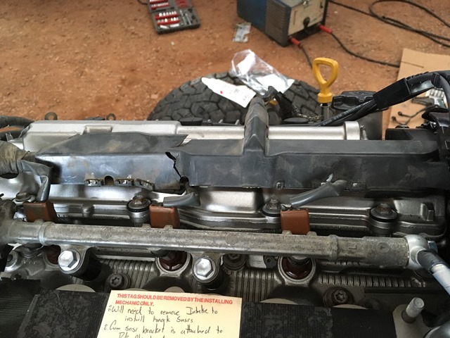
The new one had a couple bottom sections snap off too but a little electrical tape held things together.
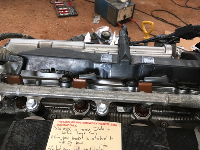
The intake manifolds were pretty dirty and oxidized from the donor. Must have been some leaks in the gasket. Probably put a catch can in this thing later to try and keep things clean on the inside. I ended up getting Super Clean degreaser and it worked like a dream. Be smart and wear gloves I didn't and my hands looked like they aged 30 years. Keep in mind super clean eats aluminum so don't let it soak overnight or anything. I dropped it in and immediately began cleaning.
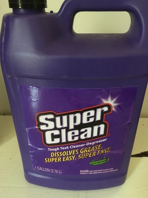
I did try gasoline on the intake manifold and it wasn't working that great. After the gasoline, 2 flushes in a tub full of Super Clean mixed at about a 3:1 ration had the inside almost looking brand new. Gasoline probably broke it loose a bit because it didn't work as fast with the intake chamber. I also took a stainless hand brush to it. Drill bit brush cup works great too but not very useful for most of the manifolds due to the form factor.
Intake before
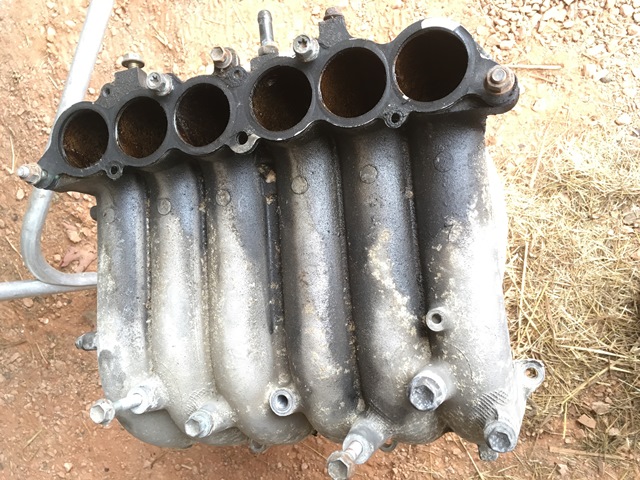
Intake after
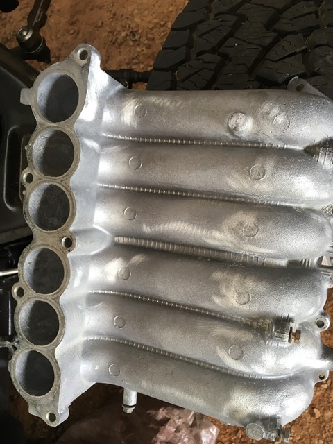
installed
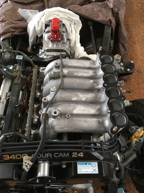
Air exchange chamber before
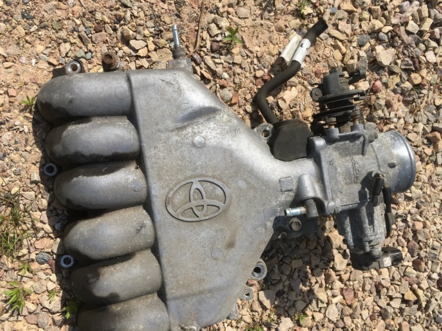
After and installed
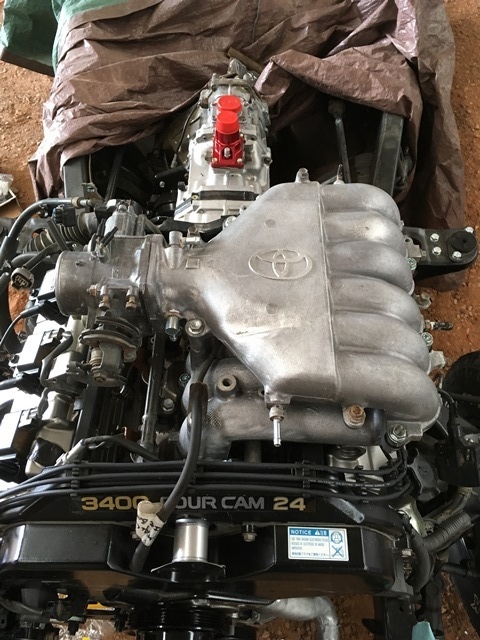
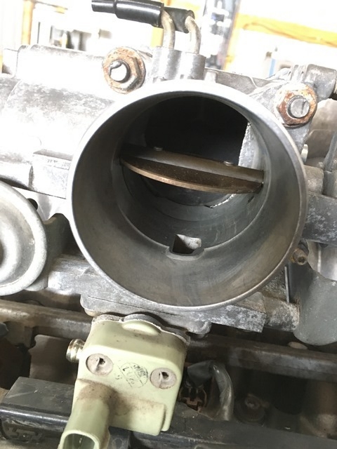
Inside the throttle body cleaned up. Left all the sensors on so this didn't get dipped in degreaser... I used carb cleaner for the inside
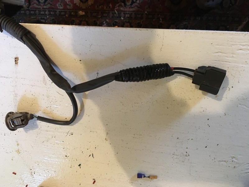
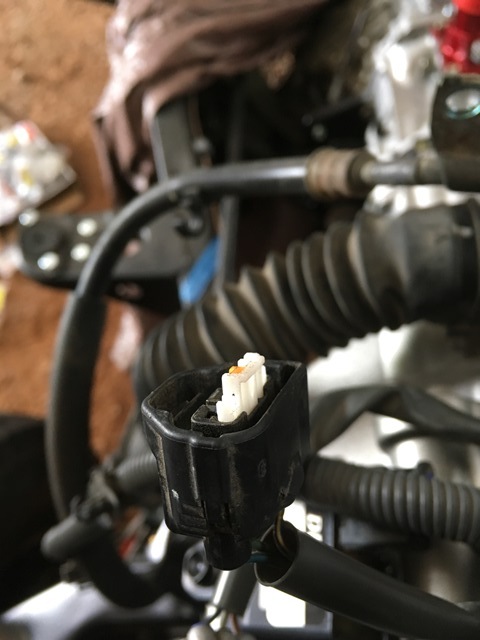
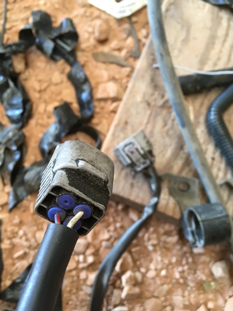
Started plugging harness plugs in and found another gem the junkyard guys gave me
Replacement wire is on order.... This one goes to the TPS. Wished I would have found it before the harness went on. Took a couple more pics this time of the disassembly. Take a flathead and pry out the white part of the plug. Should pull straight out...
Here's the black tabs I referred to earlier. Lift up on the black tab and push connector out.
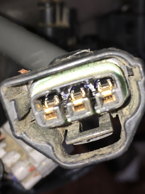
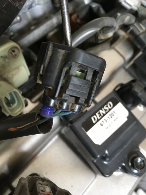
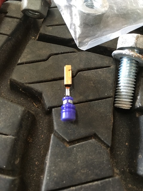
The tabs on the side of plug I referred to in the previous post just retain the rubber ring. No need to pull that out.
The driver side donor race was in much better shape than the 2000 from the junkyard. Here's the one I had split in half. Parts of the bottom were also missing...

The new one had a couple bottom sections snap off too but a little electrical tape held things together.

The intake manifolds were pretty dirty and oxidized from the donor. Must have been some leaks in the gasket. Probably put a catch can in this thing later to try and keep things clean on the inside. I ended up getting Super Clean degreaser and it worked like a dream. Be smart and wear gloves
I didn't and my hands looked like they aged 30 years. Keep in mind super clean eats aluminum so don't let it soak overnight or anything. I dropped it in and immediately began cleaning.
I did try gasoline on the intake manifold and it wasn't working that great. After the gasoline, 2 flushes in a tub full of Super Clean mixed at about a 3:1 ration had the inside almost looking brand new. Gasoline probably broke it loose a bit because it didn't work as fast with the intake chamber. I also took a stainless hand brush to it. Drill bit brush cup works great too but not very useful for most of the manifolds due to the form factor.
Intake before

Intake after

installed

Air exchange chamber before

After and installed

Inside the throttle body cleaned up. Left all the sensors on so this didn't get dipped in degreaser... I used carb cleaner for the inside

Started plugging harness plugs in and found another gem the junkyard guys gave me

Replacement wire is on order.... This one goes to the TPS. Wished I would have found it before the harness went on. Took a couple more pics this time of the disassembly. Take a flathead and pry out the white part of the plug. Should pull straight out...

Here's the black tabs I referred to earlier. Lift up on the black tab and push connector out.


The tabs on the side of plug I referred to in the previous post just retain the rubber ring. No need to pull that out.
07-14-2016, 05:58 PM
#84
Registered User
Thread Starter
Join Date: Jun 2015
Location: WI
Posts: 147
Likes: 0
Received 0 Likes
on
0 Posts
Look what came in the mail! Harness and crossover pipe from ToyOnlySwaps!
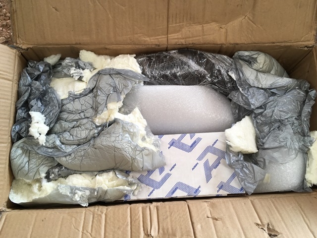
For those considering this route, the harness is around $200 cheaper than ORS. Of course I don't know the difference as I've never seen a harness from ORS but this looks pretty good
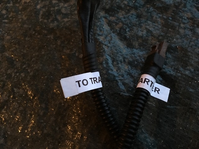
Only downside is that I put a 3.4 starter in my build and they put the 3.0 trigger wire connector on it. Wish they had a form everyone needs to fill out when shipping donor plugs so they're aware of everything. It completely slipped my mind to mention this. I'll be cutting it off and splicing on the 3.4 connector.
I was pressed for time and everyone's different but I do wish I would have done this myself It would of been a great experience and as you can see from the picture, there's only 3 plugs So to those on the fence reading this thinking about the 3.4. Take your time and save some coin!!!
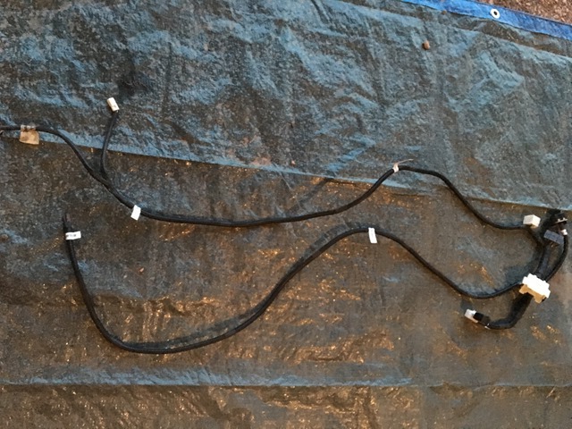
Everything is neatly loomed/heat shrinked and clearly labeled Here's the starter wire I need to swap out for the 3.4 one
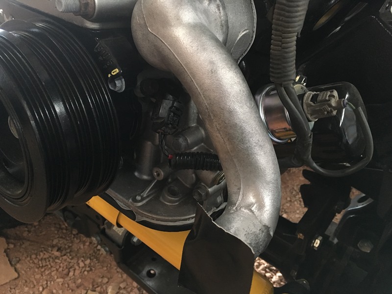
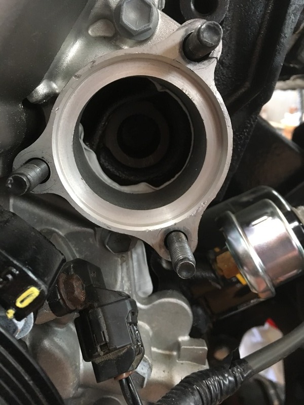
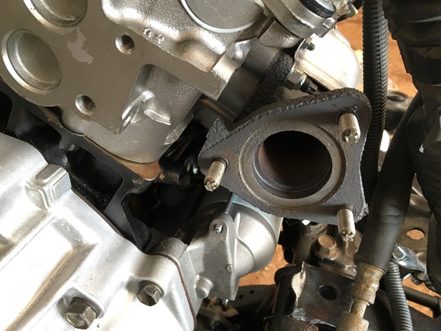
Onto the crossover pipe... I dropped in new studs
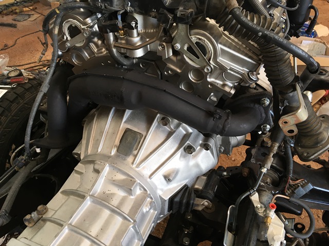
Crossover pipe looks great
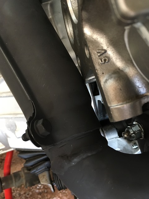
It is pinched up against the block though but it's just on the shield. Don't foresee any issues with it.
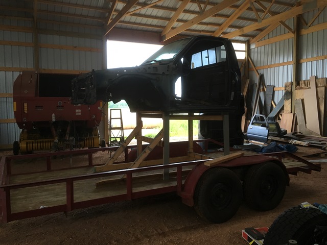
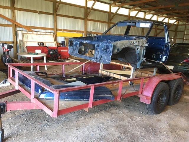
Been calling around to some body shops to get things in line. 2 weeks out for almost all of them. Prepping to get the cab shipped out so I slapped together a frame I can haul it on the trailer with a bunch of scrap wood laying around. Nice and hodgepodged

Once the frame was knocked out, I set it on the frame so I can get the hood diced up for the hood scoop. I know I could do a body lift but I already have the IFS 3" that came with the truck when I bought it in 2002. Not a fan of jacking this thing up any higher and I personally don't like the look of a body lift. So hood scoop it is as of right now.
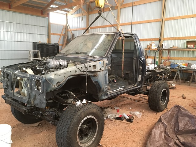
Wished it was painted already as it sits on the frame. Looks good!

For those considering this route, the harness is around $200 cheaper than ORS. Of course I don't know the difference as I've never seen a harness from ORS but this looks pretty good
Only downside is that I put a 3.4 starter in my build and they put the 3.0 trigger wire connector on it. Wish they had a form everyone needs to fill out when shipping donor plugs so they're aware of everything. It completely slipped my mind to mention this. I'll be cutting it off and splicing on the 3.4 connector.
I was pressed for time and everyone's different but I do wish I would have done this myself
It would of been a great experience and as you can see from the picture, there's only 3 plugs So to those on the fence reading this thinking about the 3.4. Take your time and save some coin!!! 
Everything is neatly loomed/heat shrinked and clearly labeled
Here's the starter wire I need to swap out for the 3.4 one
Onto the crossover pipe... I dropped in new studs

Crossover pipe looks great

It is pinched up against the block though but it's just on the shield. Don't foresee any issues with it.

Been calling around to some body shops to get things in line. 2 weeks out for almost all of them. Prepping to get the cab shipped out so I slapped together a frame I can haul it on the trailer with a bunch of scrap wood laying around. Nice and hodgepodged

Once the frame was knocked out, I set it on the frame so I can get the hood diced up for the hood scoop. I know I could do a body lift but I already have the IFS 3" that came with the truck when I bought it in 2002. Not a fan of jacking this thing up any higher and I personally don't like the look of a body lift. So hood scoop it is as of right now.


Wished it was painted already as it sits on the frame. Looks good!
07-17-2016, 06:32 PM
#85

Man, this truck will look great once done! Love how you are using the best parts possible! Same thing I did when I just redid my suspension
07-19-2016, 07:12 PM
#86
Registered User
Thread Starter
Join Date: Jun 2015
Location: WI
Posts: 147
Likes: 0
Received 0 Likes
on
0 Posts
I haven't had the chance to get to the dealer yet to fix the plug but I got the hood ready for the painter.
Hood

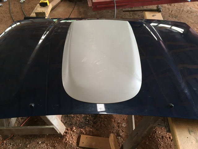
I ended up putting it on the truck and spotted everything up. Hood was pretty dusty from the blasting so I just pushed down on the outside of the hood. Where it hit I rubbed the dust off to mark

Keep in mind I have no body lift.... I was surprised how small of a hole was required. Looks like many remove the entire center support but I wanted to leave as much as possible to reduce any floppy sag. I only cut a small section out and it worked great
I used a grinder and a cutting wheel. Pretty good gap under the supports where if your careful you won't damage the hood.
Then I drilled a hole big enough where my air nibbler could get into it. Cut a hole and good to go!


I haven't done any homework here but if anyone knows where I can find some of the foam adhesive they used on the supports I'd appreciate it! Below is a pic. I'd like to dress up the remaining support with a little.
 07-20-2016, 07:02 PM
#87
Registered User
Thread Starter
Join Date: Jun 2015
Location: WI
Posts: 147
Likes: 0
Received 0 Likes
on
0 Posts
Knocked out the battery tray today. I really like the looks of the ORS tray so I copied their design.
I first cut out a bunch of templates out of cardboard and mocked it up in the engine bay. Found some 1/8" plate laying around and torched out the pieces.
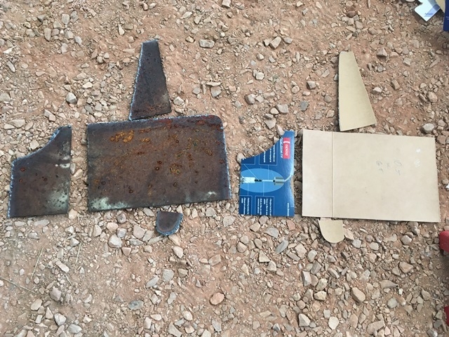
For those looking for dimensions to build one of similar geometry I can't recall off the top of my head. I believe the main square piece was 10"x6.5" and the wing where the bolt will weld on was 6.5" or so. The other part that bolts beneath the plate onto the wheel well I can't remember sorry.
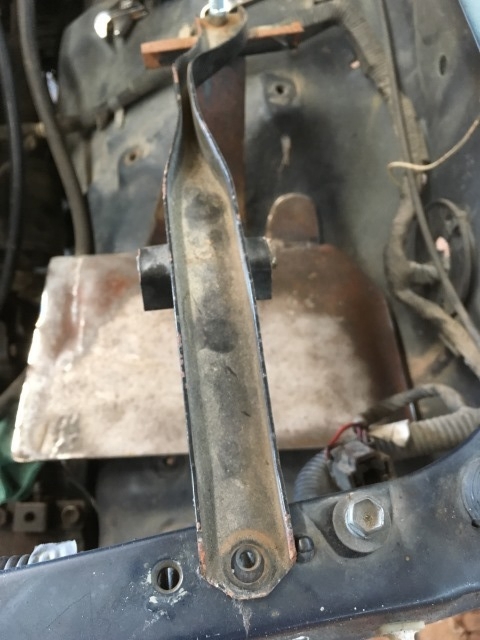
I wanted to use the existing holes from where the 3.0 air intake box was located. The next pic tested fitment and you can see the holes are inconveniently located under the plate.
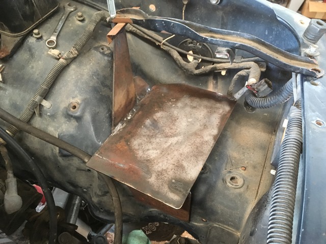
If all goes well I should be able to use this existing hole/nut on the front of the frame for the top battery bracket. I went this route as I thought it provided more security for the battery. I thought about doing 2 wings but didn't like all of the support coming from the wheel well. Also I used an 8mm bolt on top of the wing.
I then took 1" angle iron and ground down one side to approximately 3/4" so the battery wasn't so high in the bay. Drilled/grinded holes through the plate and welded them in. Also drilled the holes in the middle for the plastic tray.
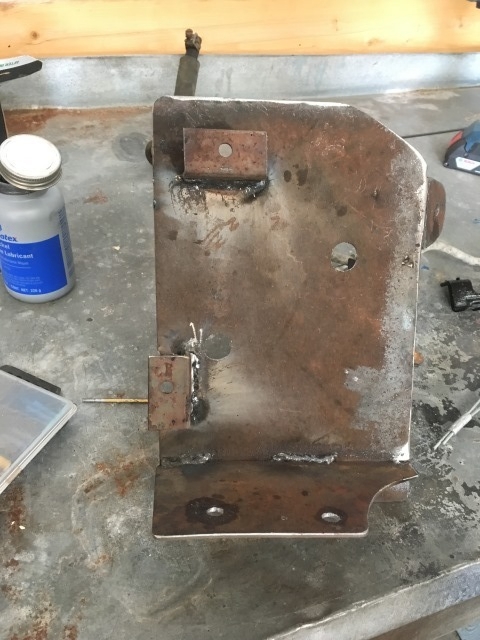
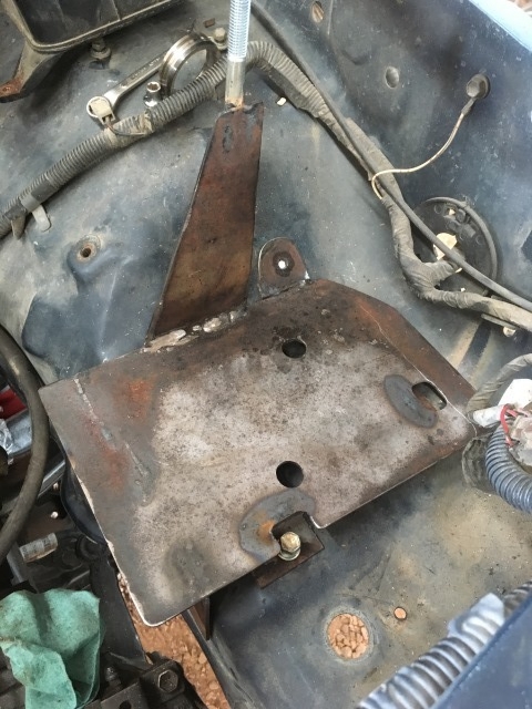
All in all I'm happy with it I had to drill one hole on the wheel well and another for the vertical support.
I first cut out a bunch of templates out of cardboard and mocked it up in the engine bay. Found some 1/8" plate laying around and torched out the pieces.

For those looking for dimensions to build one of similar geometry I can't recall off the top of my head. I believe the main square piece was 10"x6.5" and the wing where the bolt will weld on was 6.5" or so. The other part that bolts beneath the plate onto the wheel well I can't remember sorry.
I wanted to use the existing holes from where the 3.0 air intake box was located. The next pic tested fitment and you can see the holes are inconveniently located under the plate.

If all goes well I should be able to use this existing hole/nut on the front of the frame for the top battery bracket. I went this route as I thought it provided more security for the battery. I thought about doing 2 wings but didn't like all of the support coming from the wheel well. Also I used an 8mm bolt on top of the wing.

I then took 1" angle iron and ground down one side to approximately 3/4" so the battery wasn't so high in the bay. Drilled/grinded holes through the plate and welded them in. Also drilled the holes in the middle for the plastic tray.


All in all I'm happy with it
I had to drill one hole on the wheel well and another for the vertical support.
Last edited by duckhead; 07-20-2016 at 07:04 PM.
07-21-2016, 03:50 PM
#88
Registered User
Thread Starter
Join Date: Jun 2015
Location: WI
Posts: 147
Likes: 0
Received 0 Likes
on
0 Posts
Fab'd some mounts for the evap and air box. Needed to get it on the trailer today so it's ready for the painter Monday/Tuesday. I was in a bit of a hurry so I didn't take many pics. I copied alot of what's out there already but I'll be sure to show everything when it's being installed if anyone needs any ideas.
This is the mount I made for the side rail where the fender bolts on.

Like I said no pics but seems to be pretty common for a mounting location/style. I was going to build this for the front part of the evap
But I'm a bit of a fan of reusing old holes and last night I took a look at dntdad's sticky thread. In his, he just used a piece of flat stock and snuck it under the evaporator box. I copied this... 1/8" plate steel held it pretty good.
The air box front mount needs to be removed. I'm sure a saw of some sort would work but I didn't have one at the time so I took a vice grip to it Worked great
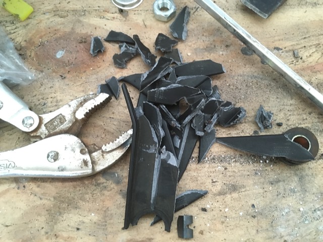
Then I took a die grinder to smooth it out.
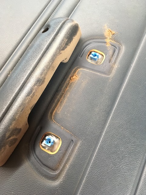
The same thing needs to happen to the rear bottom mount. There could be a way to reuse it by fabbing up some kind of mount but it runs about 45 degrees to the wheel well. Seemed like a pain to me. Some people also remove the bottom front mount but I opted to reuse it. I'm drilled one hole through the interior of the box before the filter. This shows the mounts in the front. Reused the rubber bushing from one of the plastic mounts I broke off.
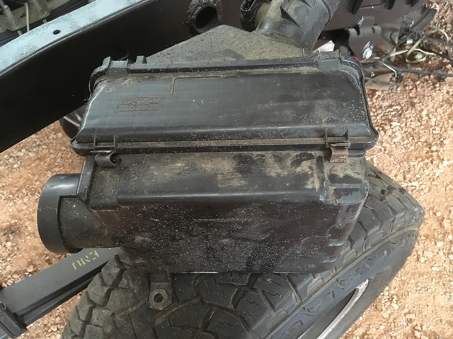
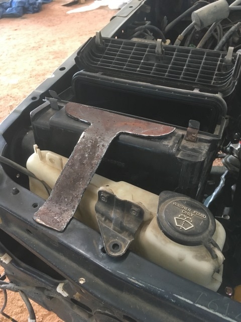
It ended up sitting pretty high. When I tried closing the hood it didn't work out I'm going to stay this course though and just shorten these by an inch or so. The rear of the box does droop a bit so I'm going to make a mount for the front top and attach it where the old batter strap used to be. This will pull the air box up and forward. I quick cut some steel and bent it to form but will be trimming it up after I get the truck back. Here's the whale tail as it is right now...
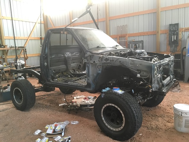
And it's loaded up on the trailer! The painter said 3' would be great but boy... Seems pretty high. I'll gut the engine bay out hopefully Monday or Tuesday before I drop it off.
This is the mount I made for the side rail where the fender bolts on.

Like I said no pics but seems to be pretty common for a mounting location/style. I was going to build this for the front part of the evap

But I'm a bit of a fan of reusing old holes and last night I took a look at dntdad's sticky thread. In his, he just used a piece of flat stock and snuck it under the evaporator box. I copied this... 1/8" plate steel held it pretty good.
The air box front mount needs to be removed. I'm sure a saw of some sort would work but I didn't have one at the time so I took a vice grip to it
Worked great
Then I took a die grinder to smooth it out.

The same thing needs to happen to the rear bottom mount. There could be a way to reuse it by fabbing up some kind of mount but it runs about 45 degrees to the wheel well. Seemed like a pain to me. Some people also remove the bottom front mount but I opted to reuse it. I'm drilled one hole through the interior of the box before the filter. This shows the mounts in the front. Reused the rubber bushing from one of the plastic mounts I broke off.

It ended up sitting pretty high. When I tried closing the hood it didn't work out
I'm going to stay this course though and just shorten these by an inch or so. The rear of the box does droop a bit so I'm going to make a mount for the front top and attach it where the old batter strap used to be. This will pull the air box up and forward. I quick cut some steel and bent it to form but will be trimming it up after I get the truck back. Here's the whale tail as it is right now...
And it's loaded up on the trailer! The painter said 3' would be great but boy... Seems pretty high. I'll gut the engine bay out hopefully Monday or Tuesday before I drop it off.
 07-30-2016, 10:02 AM
#89
Registered User
Thread Starter
Join Date: Jun 2015
Location: WI
Posts: 147
Likes: 0
Received 0 Likes
on
0 Posts
Got it to the painter this past week so here are some photos along the way. Won't post them all because there's too many random pics for when I put everything back together. If anyone wants extra or any elaboration I'll see what I can do....
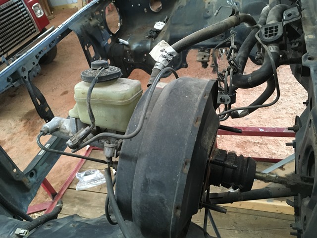
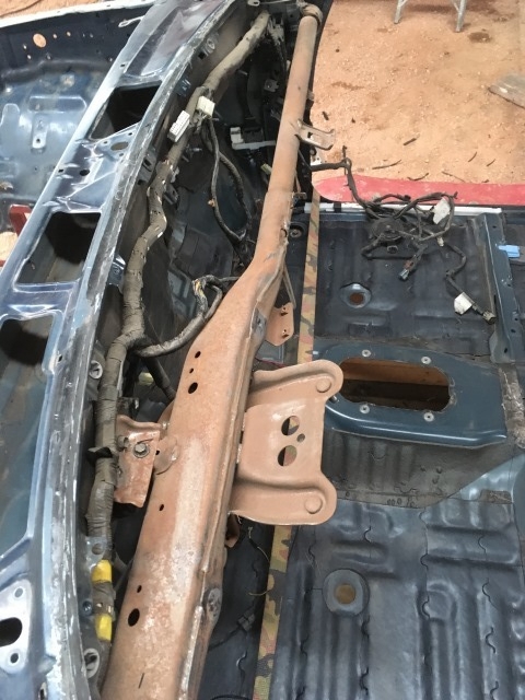
Cleaned up the firewall by trying to keep everything intact. I took out the booster with all of the lines still attached.
Marked steering shaft but not necessary at this point. Only one way to go in...
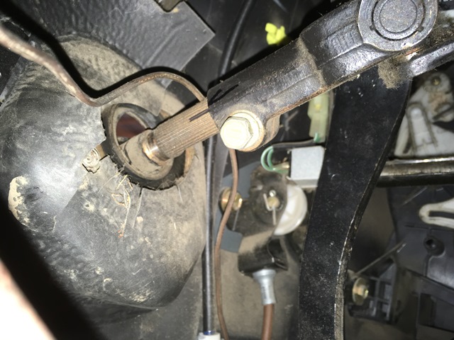
For the wiper motor it's fixed by a "button" to the wiper linkage. Remove bolts and start pulling away from firewall. Move wipers so they're extended towards the drivers side. This will move the linkage over and make it easy to remove the motor from the linkage.
Linkage moves over and gives room to work
Pops off of linkage
Tearing down the rest of the firewall is relatively self explanatory so not much to post about it.
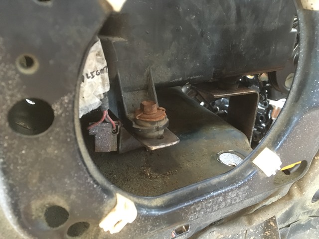
Jack mount on the rear wall started shearing off. It's been like this since I've owned it. I'm just going to get rid of it...
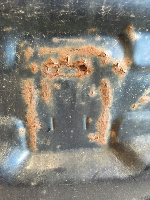
Drilled out the spot welds and removed
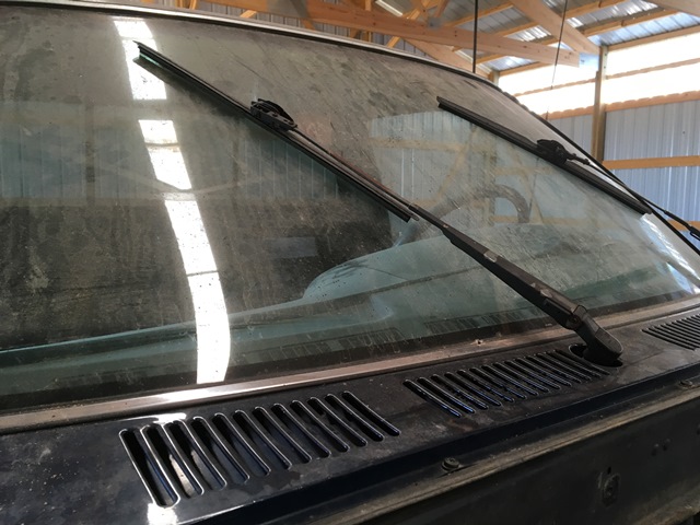
I took out the dash and pulled the front window. What a job when you don't have the right tools I'm not a window guy so I'm not sure what's standard for an install but when the window was last replaced, the guy sure put enough glue in there. Looked like they replaced the clips with glue  But maybe this is normal... I'm not sure.
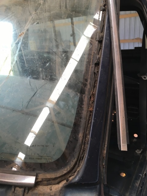
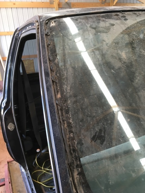
They say the window will likely break during uninstall and... it was true in this case I took a small screwdriver and tried making a hole for some braided wire. I made a hole alright...
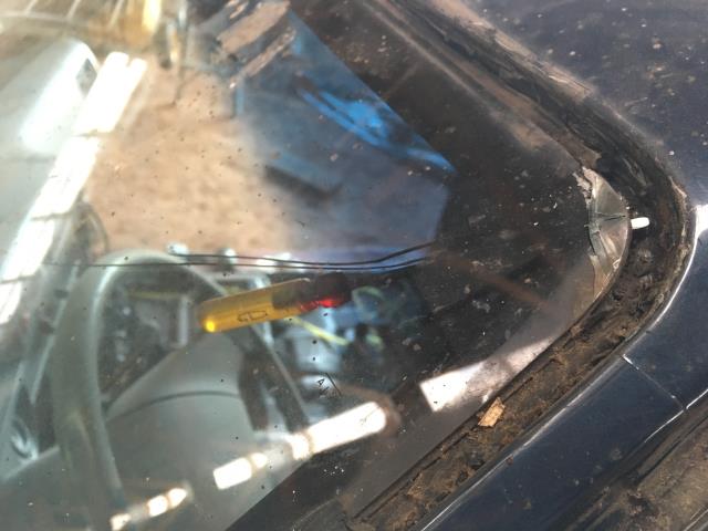
So I tried some wire and maybe the stuff I had didn't have enough tensile strength. Kept breaking and I got fed up with it. I used the oscillating tool with a saw blade for the top and sides. Worked great. Then I used a sawzall for the bottom. Sliced through real nice. But what a PITA... Glad I removed windshield. Luckily there was only surface rust but the cancer was there...
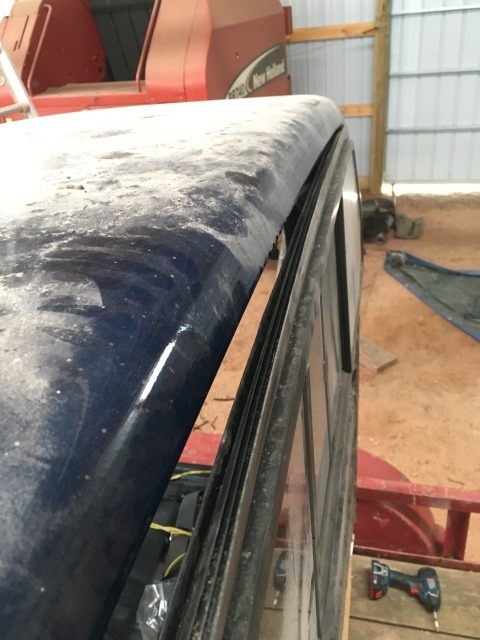
Back window is loads easier... Peel down a bit of the molding from the inside and then push out until it clears the cab lip. Then work your way down the top doing the same thing
Started on corner
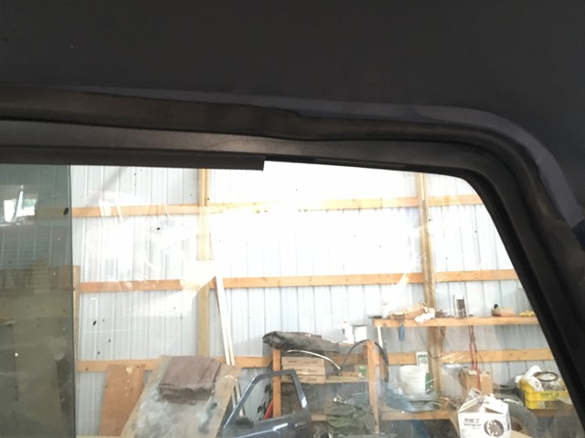
Then just pull it out
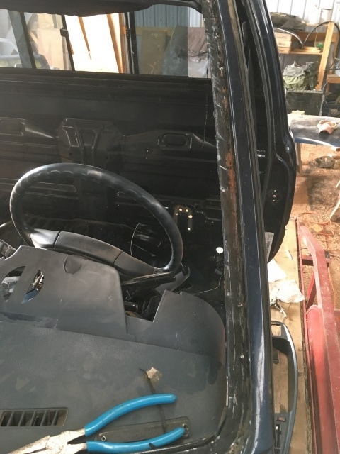
Gutted the interior
I searched around the web a bit for a hood scoop I liked. I really liked the one theMonch put on his build. It's a replica of the 4runner/tacoma. Closest thing I could find was one by 3D Carbon but I really don't like the idea of a sticker acting as the mesh on the front. I also thought about the one others have posted from racecomposites.com. I didn't like it's open functional design. I wasn't looking for this because I don't want salt spray, water, and other road debris flying into the engine bay.
Some pics of both here; https://www.yotatech.com/forums/f160...scoops-244528/
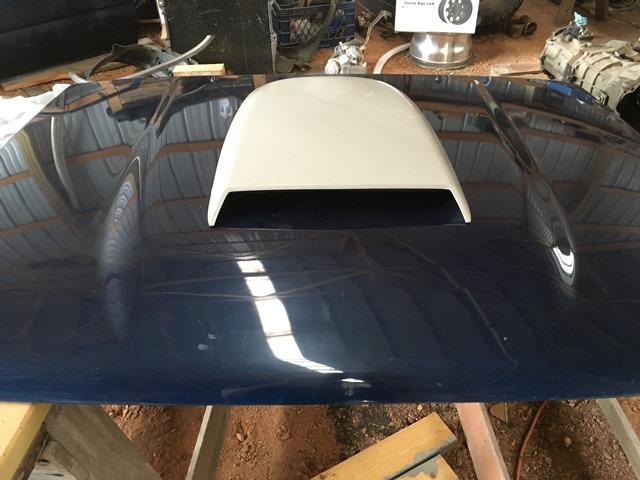
I went with the Roush 401345 scoop. I bought it from summitracing... I liked the receded blockoff so it shouldn't be visible and it comes with bolts and adhesive tape.
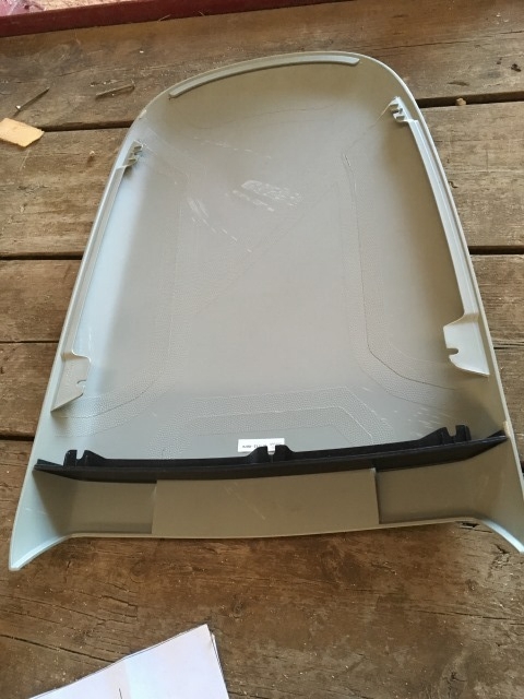
Mock up
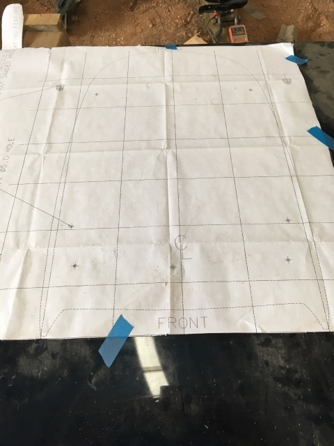
Marked the center of the hood and slapped the provided template on to drill the holes
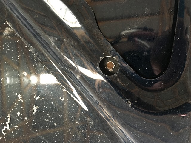
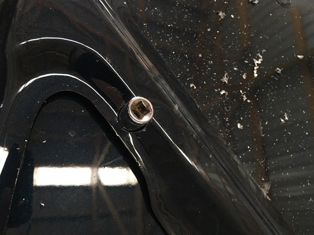
Some of the holes do go through the support channels so I drilled those out large enough so a socket will fit into them. I tried to maintain as much of the hood's structural integrity as I could
And sitting at the painter.... After talking to the shop, truck was sitting way too high to get in their paint booth. I knocked off about 18" off the existing frame to get it lower.
Cleaned up the firewall by trying to keep everything intact. I took out the booster with all of the lines still attached.

Marked steering shaft but not necessary at this point. Only one way to go in...

For the wiper motor it's fixed by a "button" to the wiper linkage. Remove bolts and start pulling away from firewall. Move wipers so they're extended towards the drivers side. This will move the linkage over and make it easy to remove the motor from the linkage.

Linkage moves over and gives room to work

Pops off of linkage

Tearing down the rest of the firewall is relatively self explanatory so not much to post about it.
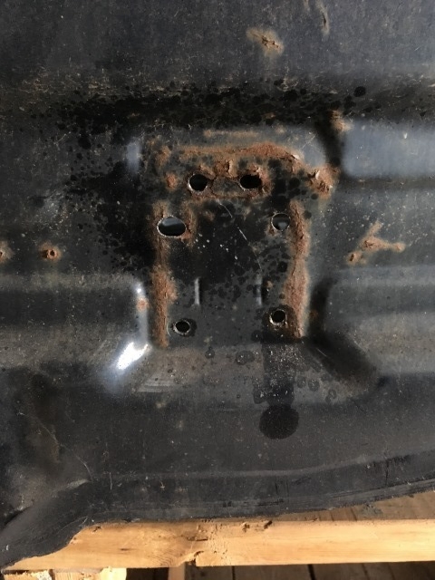
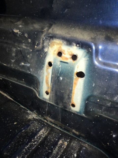
Jack mount on the rear wall started shearing off. It's been like this since I've owned it. I'm just going to get rid of it...


Drilled out the spot welds and removed


I took out the dash and pulled the front window. What a job when you don't have the right tools
I'm not a window guy so I'm not sure what's standard for an install but when the window was last replaced, the guy sure put enough glue in there. Looked like they replaced the clips with glue But maybe this is normal... I'm not sure.

They say the window will likely break during uninstall and... it was true in this case
I took a small screwdriver and tried making a hole for some braided wire. I made a hole alright...
So I tried some wire and maybe the stuff I had didn't have enough tensile strength. Kept breaking and I got fed up with it. I used the oscillating tool with a saw blade for the top and sides. Worked great. Then I used a sawzall for the bottom. Sliced through real nice. But what a PITA... Glad I removed windshield. Luckily there was only surface rust but the cancer was there...

Back window is loads easier... Peel down a bit of the molding from the inside and then push out until it clears the cab lip. Then work your way down the top doing the same thing
Started on corner

Then just pull it out

Gutted the interior


I searched around the web a bit for a hood scoop I liked. I really liked the one theMonch put on his build. It's a replica of the 4runner/tacoma. Closest thing I could find was one by 3D Carbon but I really don't like the idea of a sticker acting as the mesh on the front. I also thought about the one others have posted from racecomposites.com. I didn't like it's open functional design. I wasn't looking for this because I don't want salt spray, water, and other road debris flying into the engine bay.
Some pics of both here; https://www.yotatech.com/forums/f160...scoops-244528/
I went with the Roush 401345 scoop. I bought it from summitracing... I liked the receded blockoff so it shouldn't be visible and it comes with bolts and adhesive tape.

Mock up


Marked the center of the hood and slapped the provided template on to drill the holes

Some of the holes do go through the support channels so I drilled those out large enough so a socket will fit into them. I tried to maintain as much of the hood's structural integrity as I could


And sitting at the painter.... After talking to the shop, truck was sitting way too high to get in their paint booth. I knocked off about 18" off the existing frame to get it lower.
 08-01-2016, 05:16 PM
#90
Registered User
Thread Starter
Join Date: Jun 2015
Location: WI
Posts: 147
Likes: 0
Received 0 Likes
on
0 Posts
I went with the 3.4 alternator. Bought Denso reman from Rockauto
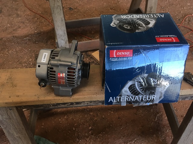
Junkyard guy struck again!!! Can't complain though... I paid for the engine harness and they sent the battery harness as a bonus.
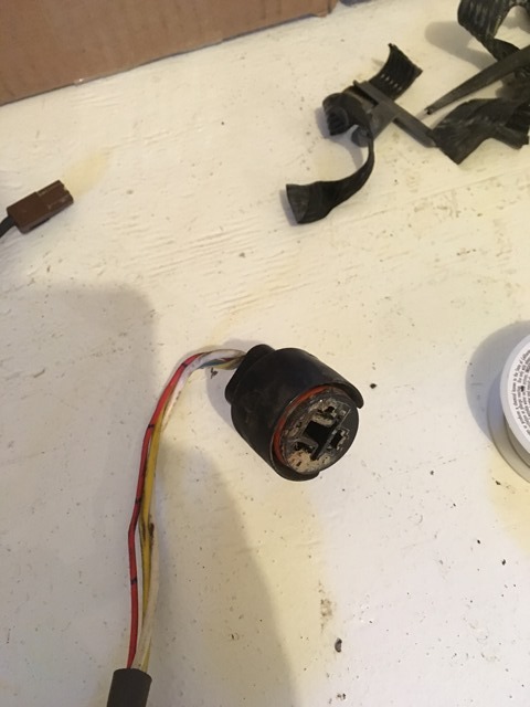
I swapped plugs from the donor vehicle which worked out pretty good. To do this, it's the same thing as the above (post 83 removing the wire) but obviously it's all 4 from the plug.
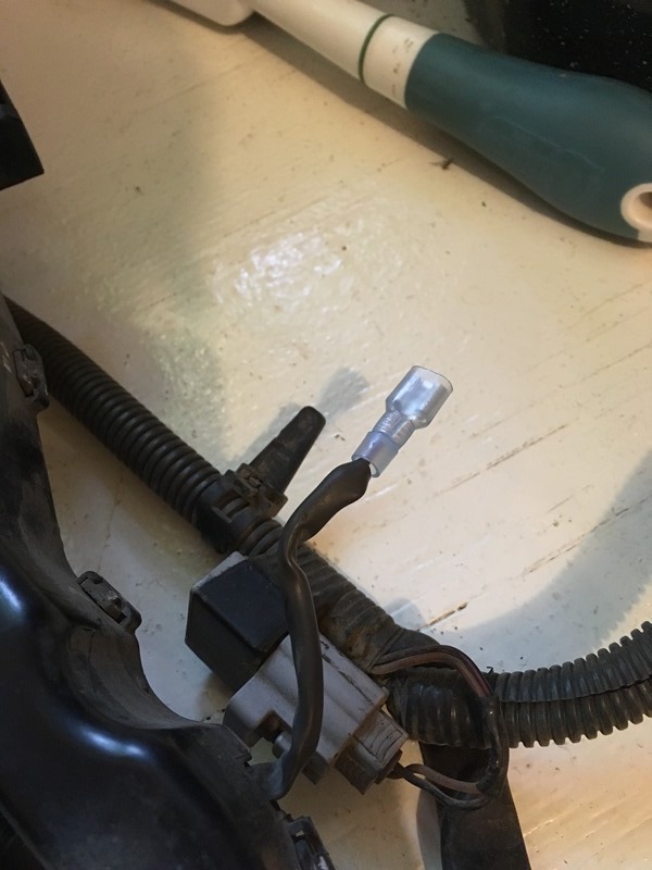
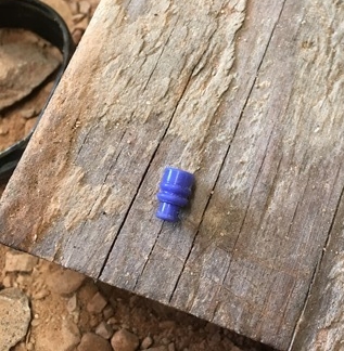
One end of the alternator wire has 3 wires while the other end has 4. This 4rth one is the starter trigger wire. For the 1999 and 2000 4runners it's a black heavier gauge wire. Should be pretty obvious which one it is... Because it's not used, I removed it from the plug and put a blank rubber one to seal it up. I had a few laying around from the broken wires I replaced...
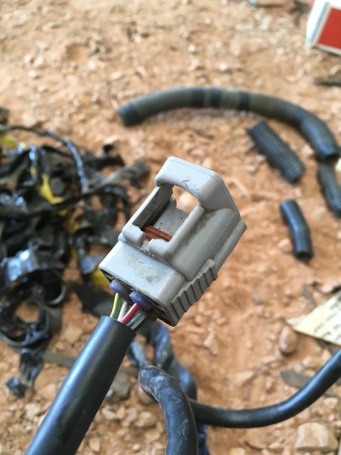
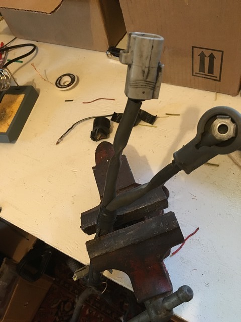
By using the 3.4 alternator, the 3.0 alternator plug needs to be changed out with the 3.4 plug that sits under the fuse box. The 3.4 plug is this one;
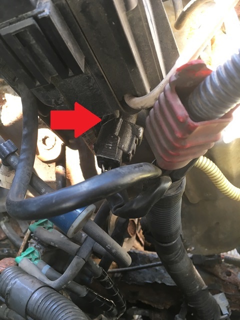
Pull up the fuse box, cut back the electrical tape, and cut the plug off.
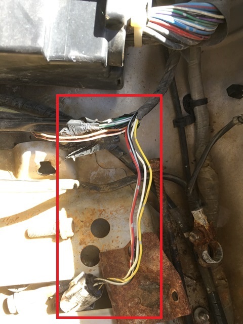
This is the 3.0 plug that needs to be swapped out. It's the one that is fastened on the drivers side wheel well
Spliced and solder. Just match the colors...
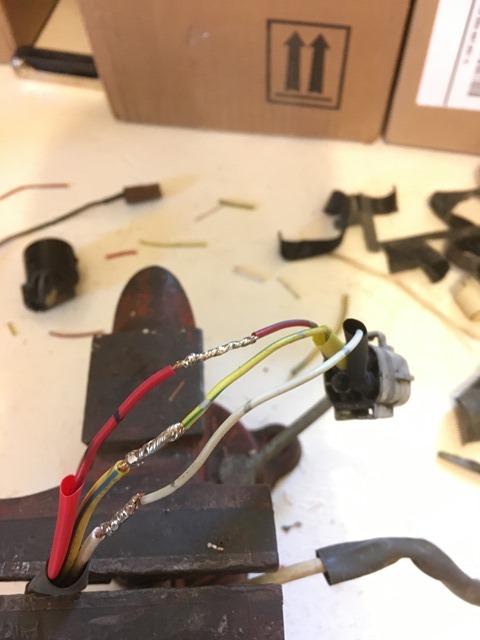
Heat shrink
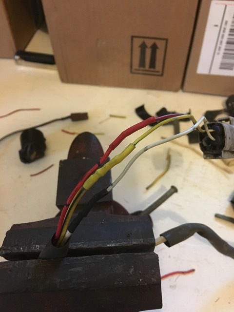
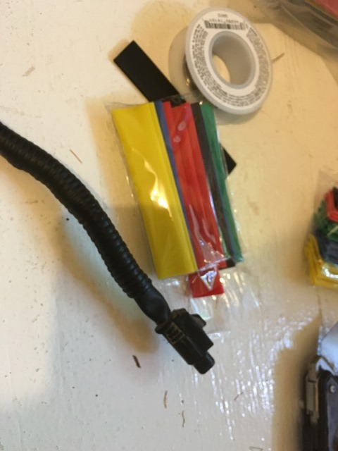
Reloom it and it's good to go. You'll notice from above I also removed the black trigger wire from the connector.
I also spliced on the 3.4 starter trigger connector onto the harness ToyOnlySwaps sent

Junkyard guy struck again!!! Can't complain though... I paid for the engine harness and they sent the battery harness as a bonus.

I swapped plugs from the donor vehicle which worked out pretty good. To do this, it's the same thing as the above (post 83 removing the wire) but obviously it's all 4 from the plug.
One end of the alternator wire has 3 wires while the other end has 4. This 4rth one is the starter trigger wire. For the 1999 and 2000 4runners it's a black heavier gauge wire. Should be pretty obvious which one it is... Because it's not used, I removed it from the plug and put a blank rubber one to seal it up. I had a few laying around from the broken wires I replaced...


By using the 3.4 alternator, the 3.0 alternator plug needs to be changed out with the 3.4 plug that sits under the fuse box. The 3.4 plug is this one;

Pull up the fuse box, cut back the electrical tape, and cut the plug off.

This is the 3.0 plug that needs to be swapped out. It's the one that is fastened on the drivers side wheel well

Spliced and solder. Just match the colors...

Heat shrink

Reloom it and it's good to go. You'll notice from above I also removed the black trigger wire from the connector.

I also spliced on the 3.4 starter trigger connector onto the harness ToyOnlySwaps sent

Last edited by duckhead; 08-01-2016 at 05:19 PM.
08-03-2016, 06:04 AM
#92
Registered User
Thread Starter
Join Date: Jun 2015
Location: WI
Posts: 147
Likes: 0
Received 0 Likes
on
0 Posts
08-16-2016, 09:24 PM
#93
Registered User
Thread Starter
Join Date: Jun 2015
Location: WI
Posts: 147
Likes: 0
Received 0 Likes
on
0 Posts
Not much to update... Cab is still at the painter as he's swamped with work.
I said the shocks would be the last thing but a promotion got the best of me Oh and buy from Rockauto if your going the RS9000 route. I didn't know they sold them for such a great price. That and they do exchanges with no questions asked! Had another "paint problem." Pretty wild in my opinion how common this is with their parts As I said, Rockauto replaced it with a good shock and even verified it's finish before shipment.
I went with 143s again in the rear for the extra length. The fronts also needed extra length. Looking at the billies, their length is close to the old ES3000s I had on. I scoured Rancho's website to match the correct code with the billie length for this model truck. The result came down to two. One was for a Kijang (rockauto didn't sell them) and the other for Ford Bronco/Ranger (RS999117). Valved differently? Sure but who knows, maybe a winch or heavier bumper may find its way into my build
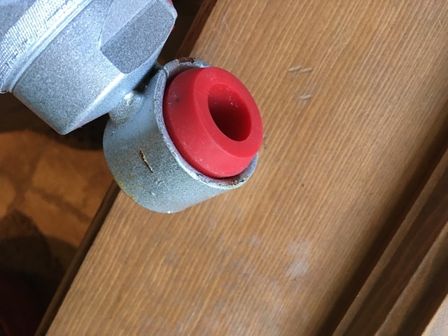
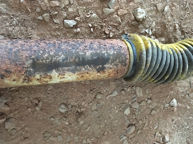
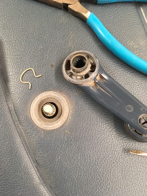
Before installing I read many people having issues with the adjustment knobs getting seized from corrosion. Best fix was to remove knob and pack with grease.
Knob removed... Yes that's rust but I give up
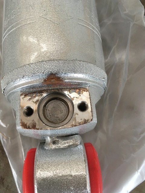
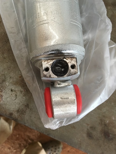
Packed with grease
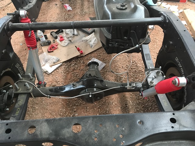
Front drivers on and then rear
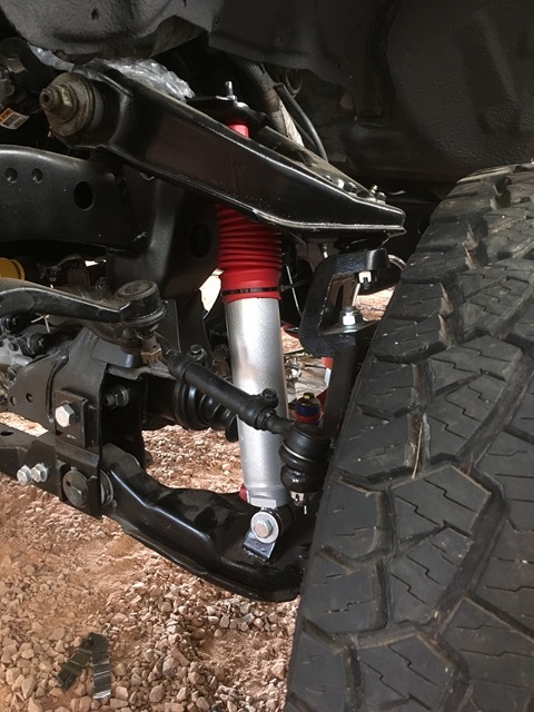
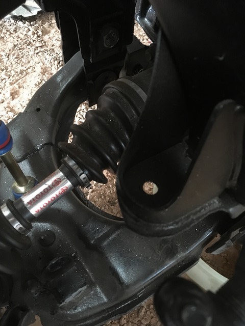
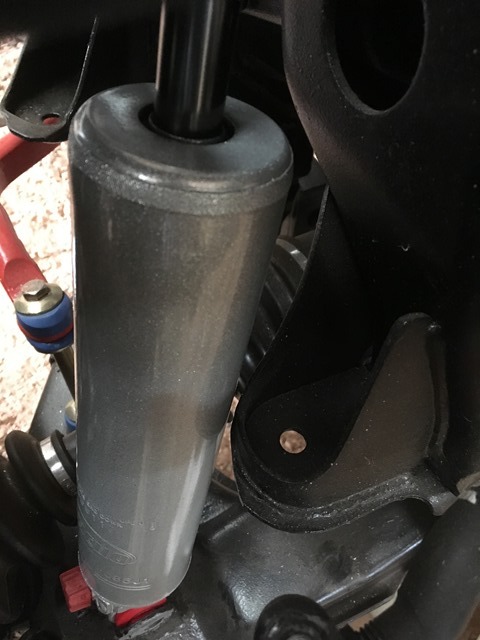
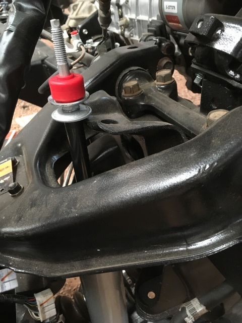
Earlier in this thread I forgot the passenger side rubbed with the old ES3000s... The installation of the other Rancho's reminded me of this problem. This is what this 3" IFS lift did to the aftermarket shocks... Hard to see in this pic but there are dents in the tube. No puncture tho
So I took a grinder to the bump stop mount...
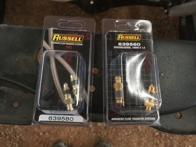
I bought speed bleeders from Summit Racing
Toyota front calipers - Russell 639560
GM calipers from the swap - Russell 639580
These fit good but keep in mind I haven't ran them yet. On the GM, the speed bleeder was exact same size. The Toyota front was much shorter but the stock bleeder had alot of thread showing. The speedbleeder still seated tight with some thread left over. I just wanted to throw this disclaimer out there in case someone buys. I will update if there are any issues when I run them.
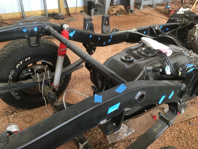
I took a look at the inner frame as best I could when I was about to put the rubber plugs back in. Some spots had a little rust in there. Like I said before, the pressure pot I bought worked but it didn't spray that well. Even when reduced to 10-15%, the masterseries silver was too thick. I didn't want to risk the coverage so I bought some Eastwood inner channel paint. Of course this should have been done before everything started getting slapped on but I have to admit. I am impressed!!! This stuff sprays awesome and gives great coverage! Hopefully it works as advertised
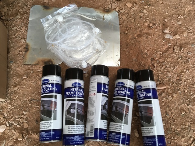
Tape up frame holes...
Tape a straightened clothes hanger to the supplied tubes so it doesn't just coil in your frame.
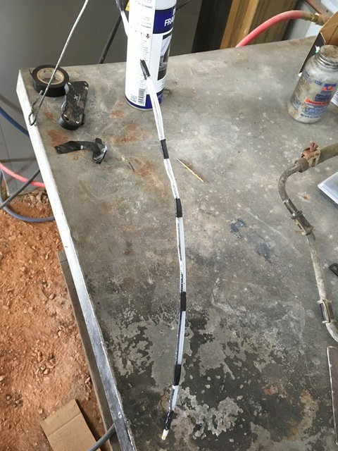
Remove tape, insert/spray, remove, retape and repeat!
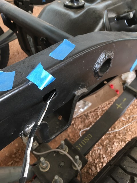
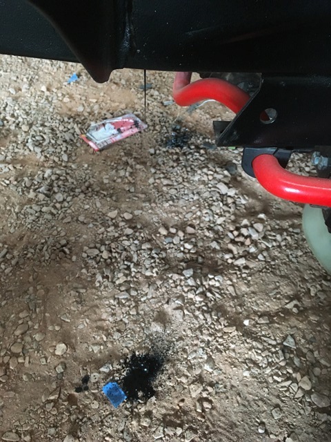
Their video does recommend running spray until it drips out of the drainage hole. Well... they compliment the notion anyway. I plugged the drainage holes. Maybe shouldn't have but was worried about spray. This is what it looked like removing one of the pieces of tape.
I ran 4 cans. 2 for each side and this included doing the very front support as well as the xmembers. Stuff was great to work with and recommend this route as opposed to the pressure pot investment but this was my experience. Inner frame looks wayyyyyy better.
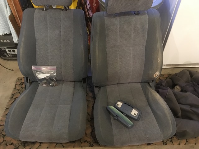
Big score today for me from craigslist. Had to drive across the state but I've been hunting for months! I could never find a blue interior but it finally sprung. Picked up these seats and the dome light. Driver seat has a little wear but at least it can be reupholstered down the road or covered with a seat cover. I'm happy anyway
I said the shocks would be the last thing but a promotion got the best of me
Oh and buy from Rockauto if your going the RS9000 route. I didn't know they sold them for such a great price. That and they do exchanges with no questions asked! Had another "paint problem." Pretty wild in my opinion how common this is with their parts As I said, Rockauto replaced it with a good shock and even verified it's finish before shipment.
I went with 143s again in the rear for the extra length. The fronts also needed extra length. Looking at the billies, their length is close to the old ES3000s I had on. I scoured Rancho's website to match the correct code with the billie length for this model truck. The result came down to two. One was for a Kijang (rockauto didn't sell them) and the other for Ford Bronco/Ranger (RS999117). Valved differently? Sure but who knows, maybe a winch or heavier bumper may find its way into my build
Before installing I read many people having issues with the adjustment knobs getting seized from corrosion. Best fix was to remove knob and pack with grease.
Knob removed... Yes that's rust but I give up

Packed with grease

Front drivers on and then rear


Earlier in this thread I forgot the passenger side rubbed with the old ES3000s... The installation of the other Rancho's reminded me of this problem. This is what this 3" IFS lift did to the aftermarket shocks... Hard to see in this pic but there are dents in the tube. No puncture tho

So I took a grinder to the bump stop mount...


I bought speed bleeders from Summit Racing
Toyota front calipers - Russell 639560
GM calipers from the swap - Russell 639580
These fit good but keep in mind I haven't ran them yet. On the GM, the speed bleeder was exact same size. The Toyota front was much shorter but the stock bleeder had alot of thread showing. The speedbleeder still seated tight with some thread left over. I just wanted to throw this disclaimer out there in case someone buys. I will update if there are any issues when I run them.

I took a look at the inner frame as best I could when I was about to put the rubber plugs back in. Some spots had a little rust in there. Like I said before, the pressure pot I bought worked but it didn't spray that well. Even when reduced to 10-15%, the masterseries silver was too thick. I didn't want to risk the coverage so I bought some Eastwood inner channel paint. Of course this should have been done before everything started getting slapped on but I have to admit. I am impressed!!!
This stuff sprays awesome and gives great coverage! Hopefully it works as advertised
Tape up frame holes...

Tape a straightened clothes hanger to the supplied tubes so it doesn't just coil in your frame.

Remove tape, insert/spray, remove, retape and repeat!

Their video does recommend running spray until it drips out of the drainage hole. Well... they compliment the notion anyway. I plugged the drainage holes. Maybe shouldn't have but was worried about spray. This is what it looked like removing one of the pieces of tape.

I ran 4 cans. 2 for each side and this included doing the very front support as well as the xmembers. Stuff was great to work with and recommend this route as opposed to the pressure pot investment but this was my experience. Inner frame looks wayyyyyy better.
Big score today for me from craigslist. Had to drive across the state but I've been hunting for months! I could never find a blue interior but it finally sprung. Picked up these seats and the dome light. Driver seat has a little wear but at least it can be reupholstered down the road or covered with a seat cover. I'm happy anyway
 08-22-2016, 04:29 AM
#94
Registered User
Thread Starter
Join Date: Jun 2015
Location: WI
Posts: 147
Likes: 0
Received 0 Likes
on
0 Posts
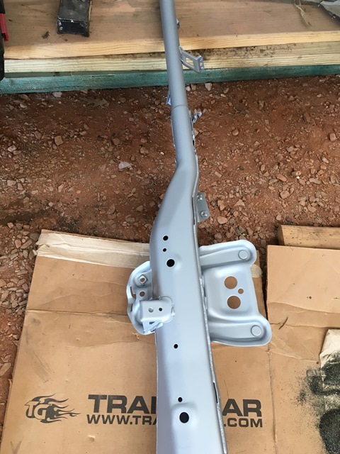
I painted the interior cross member piece silver. Had some surface rust on the very top of it which can be seen in previous post before I shipped the cab out to get painted. With the truck getting painted I had that kind of time I suppose...
Stereo brackets had a little surface rust on them too. Not bad but I was painting that other piece anyway.
Before
After
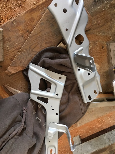
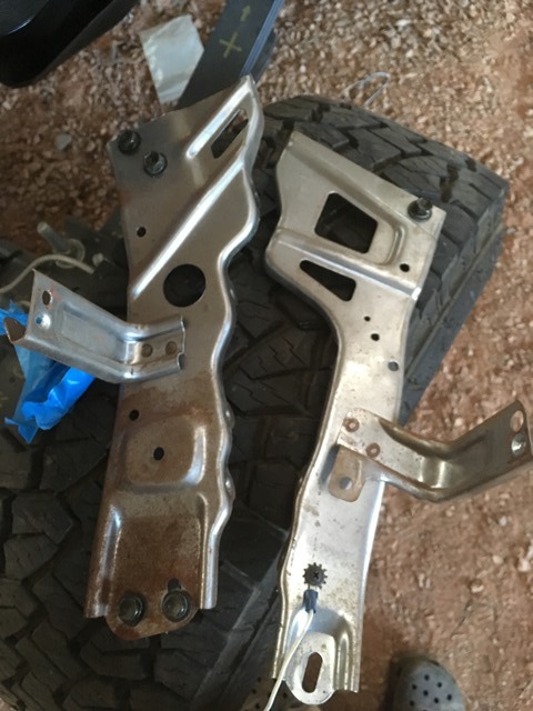
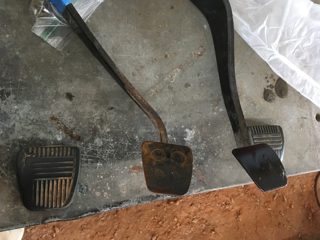
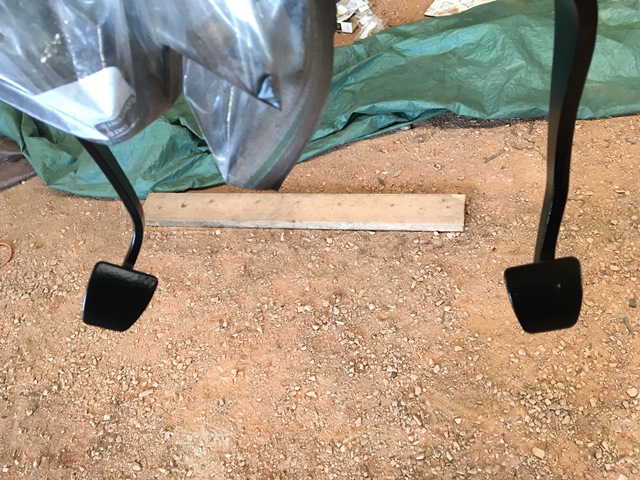
Clutch and brake pedal had some rust on em. Blasted em off and painted em.
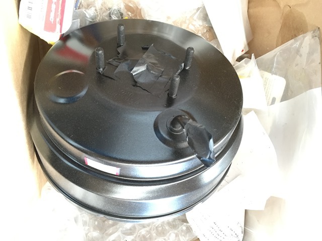
Repainted the brake booster a bit ago. For this I just scratched it up a bit and then painted over it. I was going to completely disassemble it to paint the case but I couldn't get it apart. Good enough anyway. Some dust settled on it already...
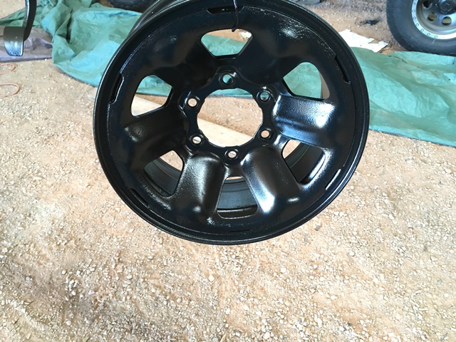
Not sure if anyone remembers the rim shot of the spare tire from the first page but it was pretty rusty from sitting under the bed. I blasted it and painted it. It's pitted in spots but looks alot better than before.
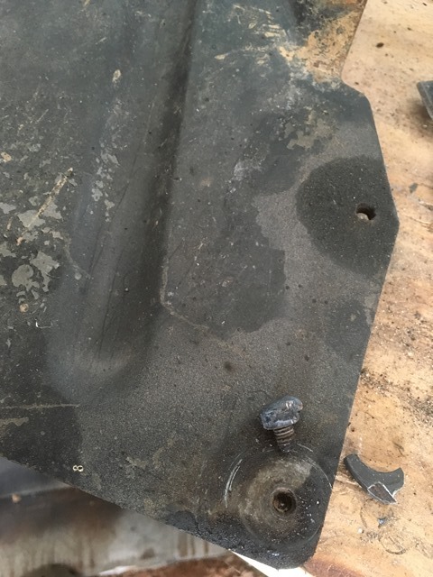
I've had to weld on some nuts on quite a few broken bolts lately. I didn't document all of them but here's a picture of the steel plate for the mud flaps. I could have drilled them out but sacrificing some old nuts seemed alot faster than drilling and tapping. Most of the time I welded enough to make sure it wouldn't twist off so a box wrench would no longer work. Used a vice grips then to get it out.
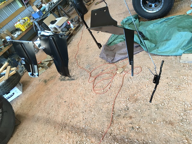
Then painted the flaps, battery, evaporator box, and muffler parts

Stereo brackets had a little surface rust on them too. Not bad but I was painting that other piece anyway.
Before

After

Clutch and brake pedal had some rust on em. Blasted em off and painted em.


Repainted the brake booster a bit ago. For this I just scratched it up a bit and then painted over it. I was going to completely disassemble it to paint the case but I couldn't get it apart. Good enough anyway. Some dust settled on it already...

Not sure if anyone remembers the rim shot of the spare tire from the first page but it was pretty rusty from sitting under the bed. I blasted it and painted it. It's pitted in spots but looks alot better than before.

I've had to weld on some nuts on quite a few broken bolts lately. I didn't document all of them but here's a picture of the steel plate for the mud flaps. I could have drilled them out but sacrificing some old nuts seemed alot faster than drilling and tapping. Most of the time I welded enough to make sure it wouldn't twist off so a box wrench would no longer work. Used a vice grips then to get it out.

Then painted the flaps, battery, evaporator box, and muffler parts

Last edited by duckhead; 08-22-2016 at 04:30 AM.
08-25-2016, 08:18 PM
#95
Registered User
Thread Starter
Join Date: Jun 2015
Location: WI
Posts: 147
Likes: 0
Received 0 Likes
on
0 Posts
Forgot to show the travel on the 117s. Big difference from the shocks that are supposed to be for a 3" lifted pickup.
I didn't send the doors in with everything else because I was trying to find something in better shape. Also something with power windows. I'd like to do the conversion but I couldn't find any doors in my area that were in decent shape. Most had holes rusted through them. I had lip rust on mine but no where near as bad as the others in the junkyard... So I decided I was going to keep my door and maybe do the power window conversion on mine. So I need to treat my lip rust. Stripping my doors was first...
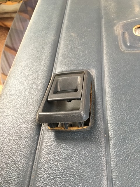
Lift window handle up and peel the clip off the handle.
Take off the handle
Pop this clip out
"Open" the door handle after taking out screw and pull back. Not hard, could break it... Should pop out and then remove the rod
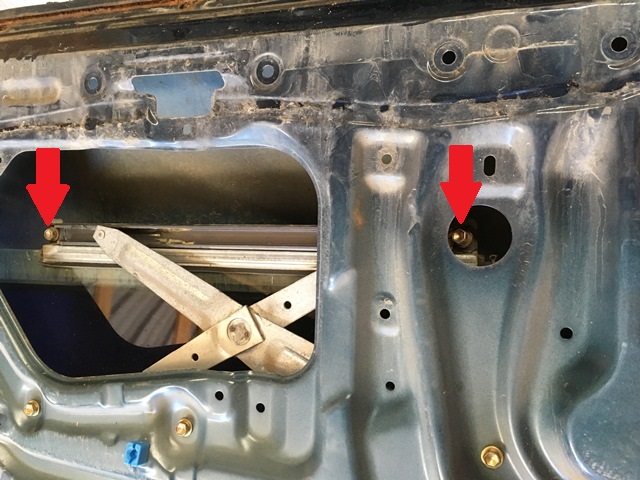
Remove window bolts (2)
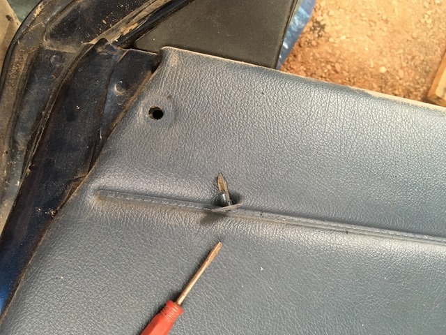
Remove trim piece with a flat head screw driver. Good idea to roll window down all the way to get this off. I removed gasket here too
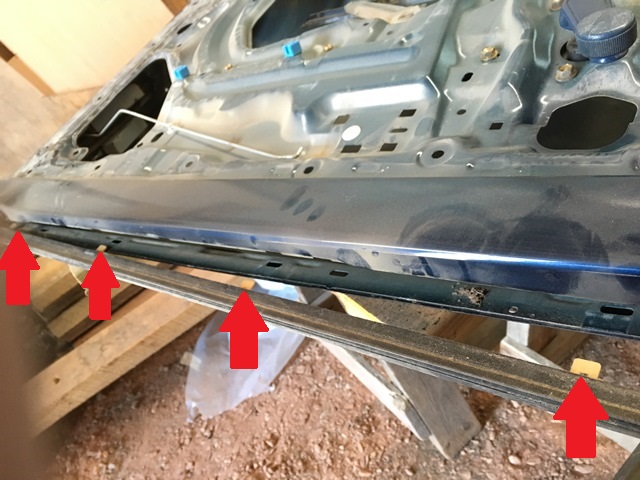
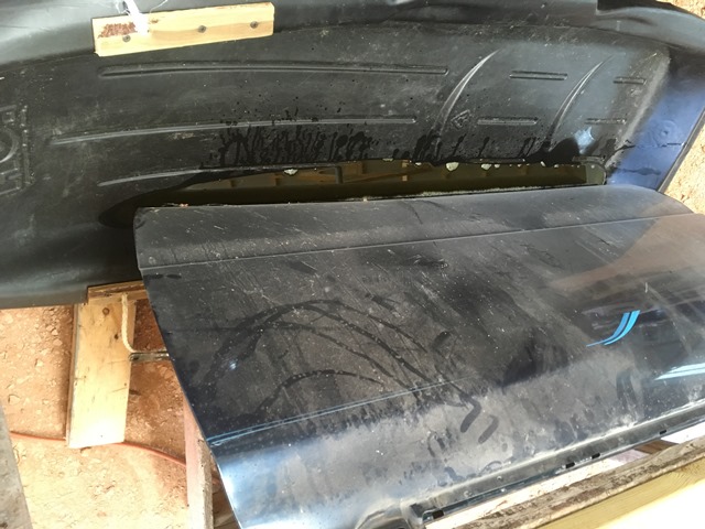
The mirror and door handle seemed self explanatory so I didn't take any pics. I peeled the seam sealer off the bottom of the door and then sandblasted it. Yikes
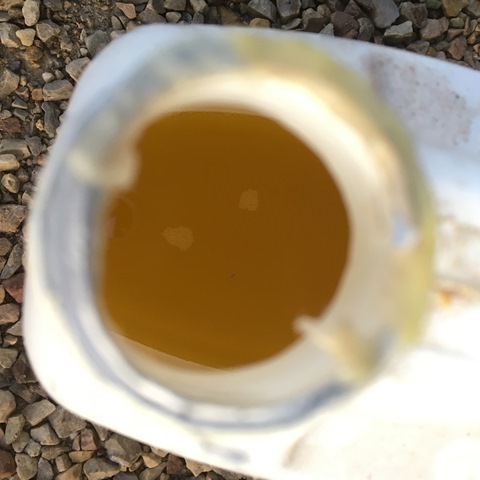
The lip rust was worse than I thought it was. The seam was lifted with big chunks of rust still under it. I didn't feel like cutting everything out and putting a new piece of steel in, even though this would be the right thing to do. I wanted to try an acid dip to see how it would work and if it did, how long. I was going to use HCl to eat all of the rust up but I thought it might be too aggressive. I was worried I wouldn't be able to neutralize this acid in the seams. I went with my metal etch solution which was phosphoric acid. Leaves the converted rust in place and it's ready to paint. For the "dip" I used an old sled and tilted it on its side to get some depth to it.
This is the initial foam/bubbles when it was put in
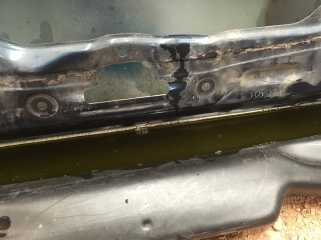
Acid is really getting after it
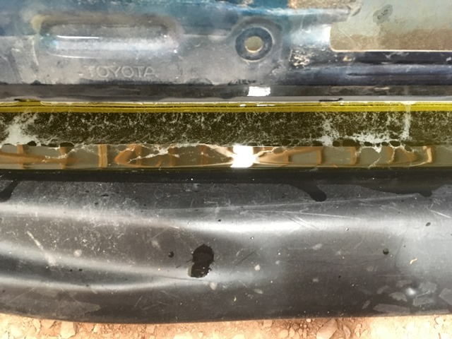
It's slowing down
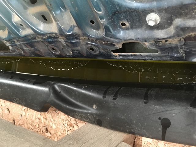
And it's basically finished.
I then took a hose to wash off as much as the acid I could. When I finished with the rinse, I took the heat gun to it in order to avoid flash rust. Turned out pretty good!
Let it air dry for a few days to make sure no moisture is in it before I seal it with the silver paint. The best thing about the acid route is it's reusable! I took a paint filter and dumped it back in the jug
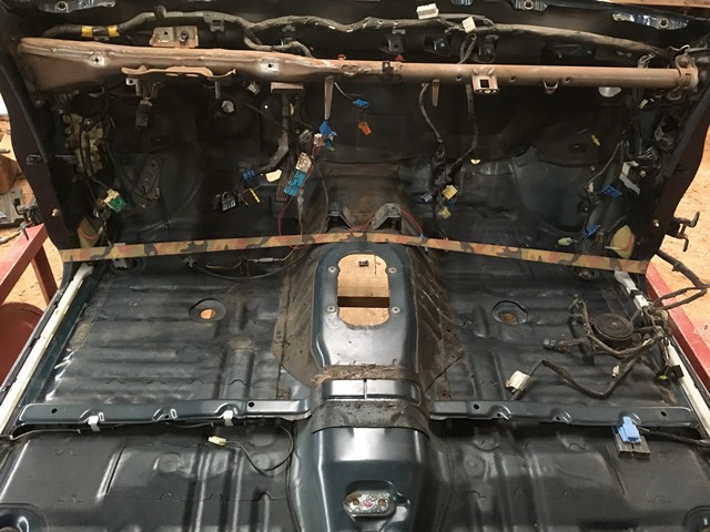
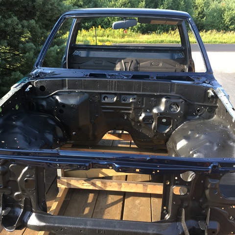
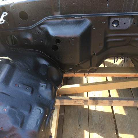
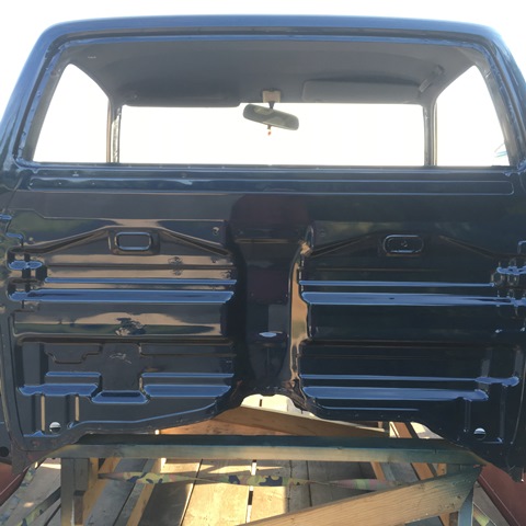
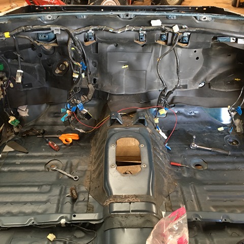
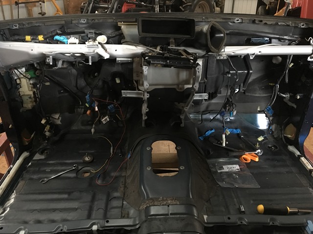
Finally!!! Cab is done along with hood and fenders. Will take pics of those later but here's the cab. Pulled it in, gonna pull the wiring and stock insulation/sound deadening off the firewall to add my own deadening.
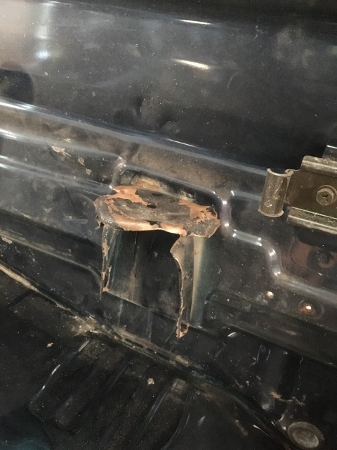
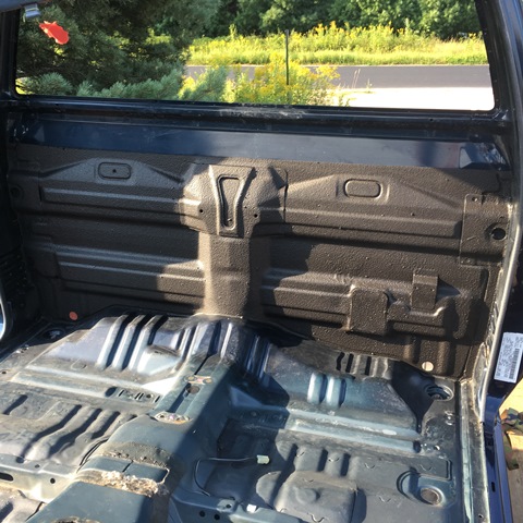
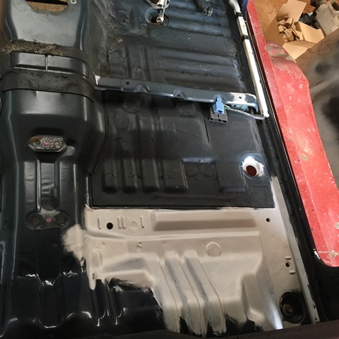
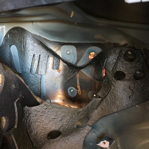
I had him put in bedliner in the engine bay for a little durability. Won't need to worry so much about a wrench scratching or chipping any paint. I had him do the front strap in blue. The back wall can be seen in this pic too. He let me go to his shop before he painted and let me spray the sound deadener on it.
Here's the deadener. We cut a plate out and welded it on the wall to fill those holes where the jack stand was.
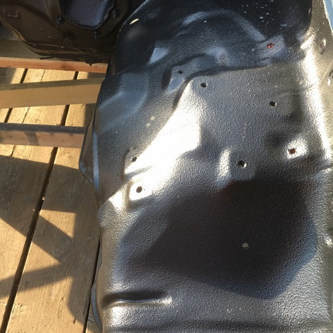
The bedliner in the engine bay
back
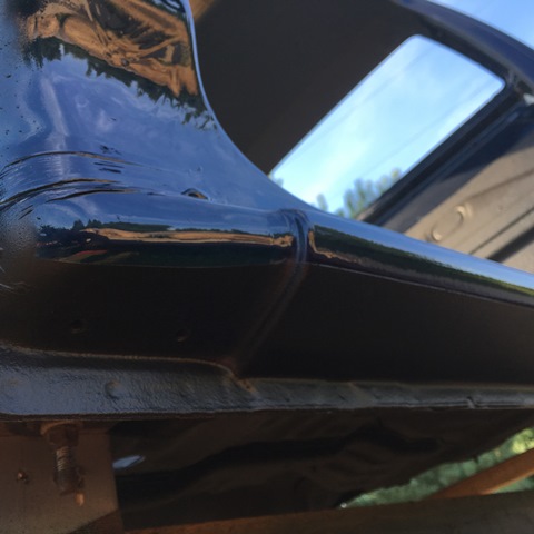
and had bedliner on the rocker panels for some chip guard
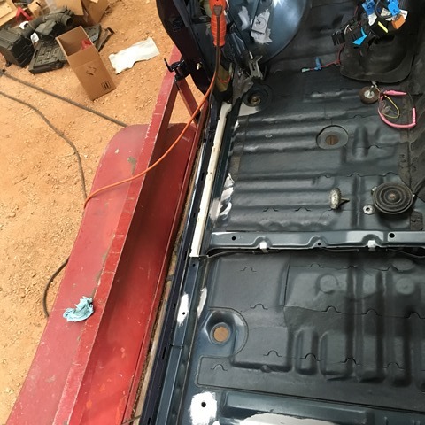
When I got it under the roof I retapped all the nuts. I spot treated the interior where there was some surface rust. When I took the carpet off I left it piled up on the passenger side. This made a big chunk of it blister all over. I wire wheeled the blisters off and painted over that too.

I didn't send the doors in with everything else because I was trying to find something in better shape. Also something with power windows. I'd like to do the conversion but I couldn't find any doors in my area that were in decent shape. Most had holes rusted through them. I had lip rust on mine but no where near as bad as the others in the junkyard... So I decided I was going to keep my door and maybe do the power window conversion on mine. So I need to treat my lip rust. Stripping my doors was first...
Lift window handle up and peel the clip off the handle.

Take off the handle

Pop this clip out

"Open" the door handle after taking out screw and pull back. Not hard, could break it... Should pop out and then remove the rod

Remove window bolts (2)

Remove trim piece with a flat head screw driver. Good idea to roll window down all the way to get this off. I removed gasket here too

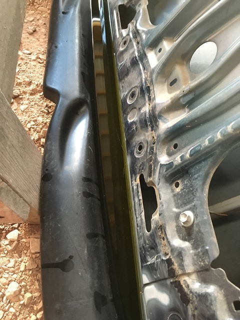
The mirror and door handle seemed self explanatory so I didn't take any pics. I peeled the seam sealer off the bottom of the door and then sandblasted it. Yikes

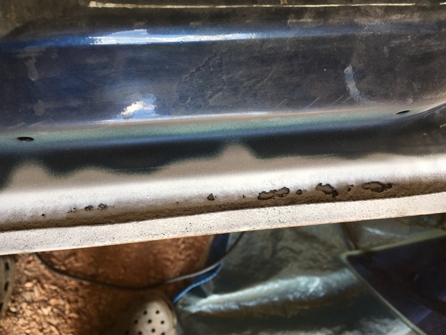
The lip rust was worse than I thought it was. The seam was lifted with big chunks of rust still under it. I didn't feel like cutting everything out and putting a new piece of steel in, even though this would be the right thing to do. I wanted to try an acid dip to see how it would work and if it did, how long. I was going to use HCl to eat all of the rust up but I thought it might be too aggressive. I was worried I wouldn't be able to neutralize this acid in the seams. I went with my metal etch solution which was phosphoric acid. Leaves the converted rust in place and it's ready to paint. For the "dip" I used an old sled and tilted it on its side to get some depth to it.

This is the initial foam/bubbles when it was put in

Acid is really getting after it

It's slowing down

And it's basically finished.

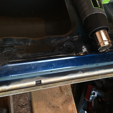
I then took a hose to wash off as much as the acid I could. When I finished with the rinse, I took the heat gun to it in order to avoid flash rust. Turned out pretty good!

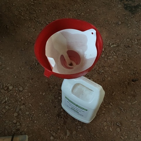
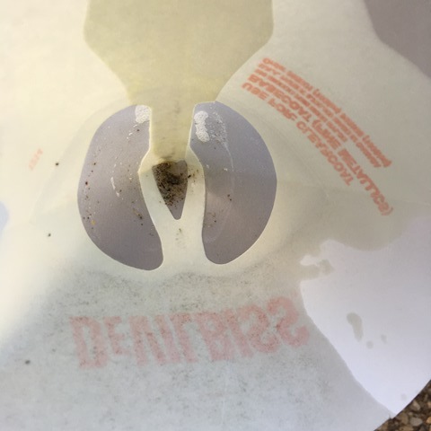
Let it air dry for a few days to make sure no moisture is in it before I seal it with the silver paint. The best thing about the acid route is it's reusable! I took a paint filter and dumped it back in the jug


Finally!!! Cab is done along with hood and fenders. Will take pics of those later but here's the cab. Pulled it in, gonna pull the wiring and stock insulation/sound deadening off the firewall to add my own deadening.
I had him put in bedliner in the engine bay for a little durability. Won't need to worry so much about a wrench scratching or chipping any paint. I had him do the front strap in blue. The back wall can be seen in this pic too. He let me go to his shop before he painted and let me spray the sound deadener on it.

Here's the deadener. We cut a plate out and welded it on the wall to fill those holes where the jack stand was.

The bedliner in the engine bay


back

and had bedliner on the rocker panels for some chip guard

When I got it under the roof I retapped all the nuts. I spot treated the interior where there was some surface rust. When I took the carpet off I left it piled up on the passenger side. This made a big chunk of it blister all over. I wire wheeled the blisters off and painted over that too.


Last edited by duckhead; 08-25-2016 at 08:23 PM.
08-25-2016, 09:40 PM
#96
Wow cab looks really good! Nice work on the door rust too.
08-26-2016, 03:36 PM
#97
Registered User
Great job on the whole thing, its going to be better than new when you are done. Should be a blast to drive around again!! Really fun to read through and follow along. So they are going to paint your parts at separate times? He was not worried about color matching at all?

 08-27-2016, 09:33 PM
#99
Registered User
Thread Starter
Join Date: Jun 2015
Location: WI
Posts: 147
Likes: 0
Received 0 Likes
on
0 Posts
Cleared off the rest of the cab to do the sound deadening. I didn't take off the internal fuse block on the drivers side or the plug junction on the passenger. Didn't want to break any clips... Few of the metal parts had surface rust like that on the main cross member in the cab. I didn't feel like painting it so I just took some of the phosphoric acid to it. Probably didn't need to do it but it took it off quick.
Before
After
I also did the steering column this way too. The before pic should be in a previous post I believe. It was pretty rusty but it basically wiped off with the acid...
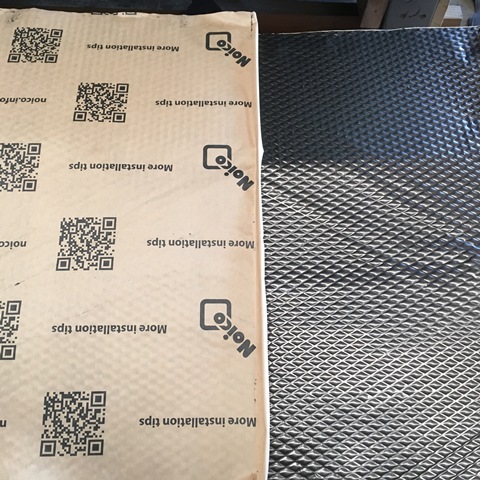
For the sound deadening a guy could but a kit or the big names out there. I wanted to try and save some coin and go the DIY route. I bought some 1/8"x42"x72" EPDM/neoprene/SBR blend CCF on ebay. I then found some 4'x10' 1lb/sq ft MLV on amazon. I think the vendor was acoustic research on amazon. I also got Noico brand CLD off amazon too. I think this route was a huge money saver compared to the big box store for what I got.
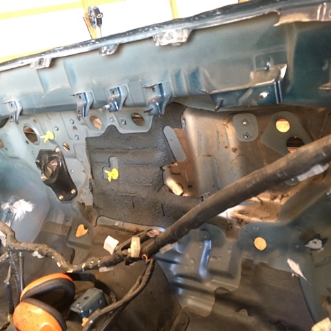
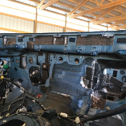
Old deadener was hanging off the firewall when I removed the factor MLV mat.
Pulled the hanging junk off
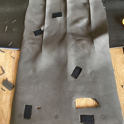
CCF mocked up
MLV was cut the same way then some industrial strength Velcro strips placed in vertical places to help hold it. Cut out the CCF where the strips are at.
Busted out Noico and put it on the firewall. I bought the black foil
Still seemed "tingy" where I placed it... Maybe it'll help a bit. Better than nothing.
Hung my MLV/CCF mats up. This is half. Where there were bends I sliced it and then put a narrower strip over it to seal. I used HH-66 vinyl cement to bond the pieces. This goes for the CCF/MLV too.
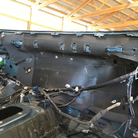
Firewall fully covered. Yes those are pink safety glasses I couldn't find mine so I used my niece's BB gun glasses
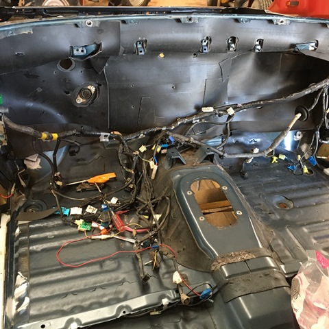
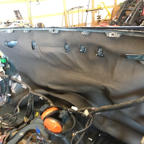
And I put the factory deadener mat up with the cables redressed. If you go this route it will be tight! but worth it in my opinion...
Replaced the gaskets on the clutch/brake cylinders and the booster. For those interested here's the part numbers;
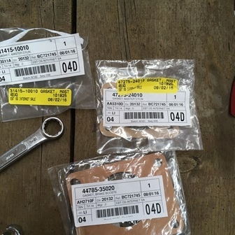
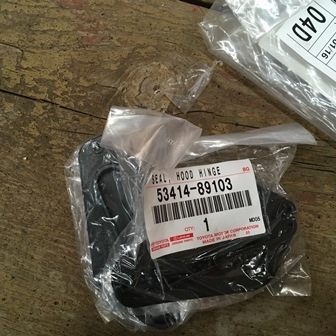
Hood hinge seals were blown. Replaced those
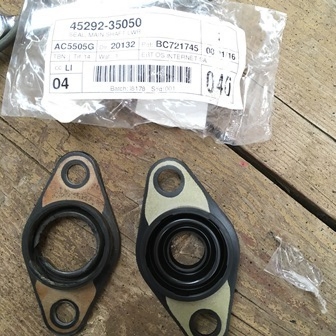
Steering shaft seal also blown
As a preventative measure I replaced the brake and clutch pedal plastic bushings
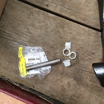
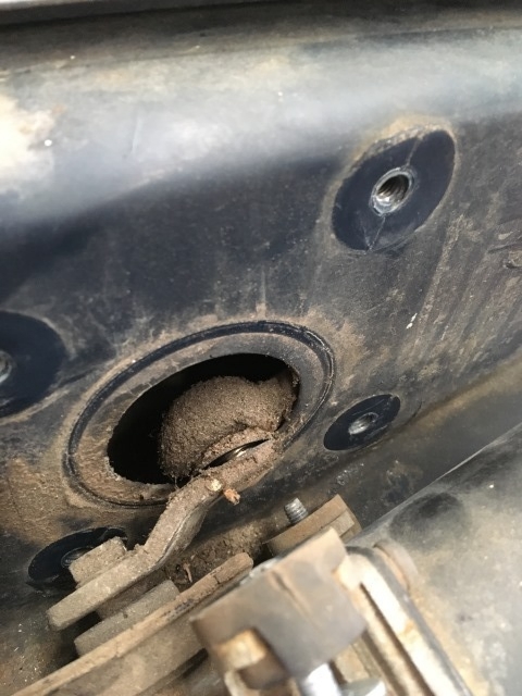
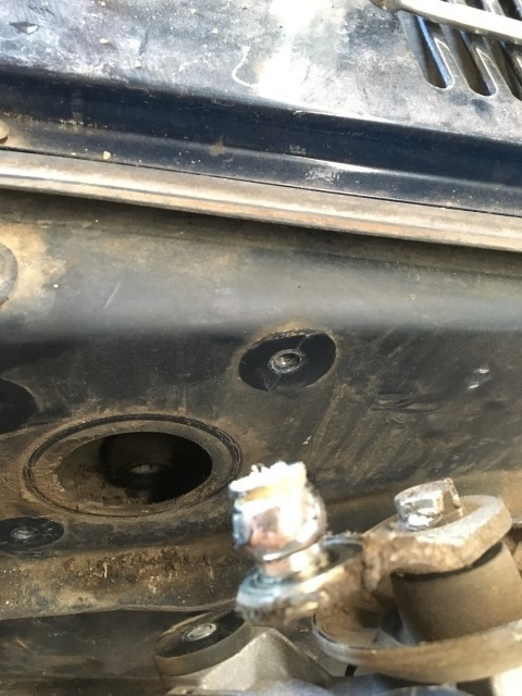
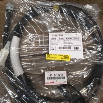
The winter before I ripped this apart the speedo cable began the 300 dB groan. The kind of sound that makes you think your truck is about to explode. Could have oiled the old one... But... It's easy right now to replace.
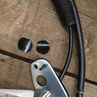
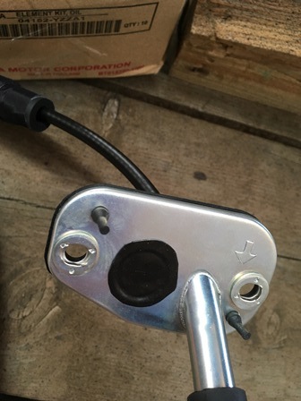
Problem is it has that extra hole and I no longer have an E-brake. I didn't have any rubber plugs laying around that would fit. I took some self fusing emergency tape and made a plug. I'm curious how long it holds up. I put two unpeeled pieces together and cut a circle that fit. Unpeeled the backing and plugged it up
I went to work on the heater core. I bought a replacement Spectra brand. May have seen on some of the dates on the Toyota parts packages they go back a ways. I'm a bit of a planner. I bought this heater core months ago. I didn't realize there was a separate copper tube for the inlet. I took a look at the galvanic series chart and copper and aluminum don't get along to well I contacted
Spectra thinking they would sell an aluminum tube... NOPE. So I'm going to make this old copper core work. I took a look inside and oh boy. On the inlet side it looks like the inside is growing some kind of grey fungus. I wished I would have taken a picture before I started cleaning. each tube had junk "growing" out of it. I pulled the big chunks out and here's a shot where a tube has a little bit left
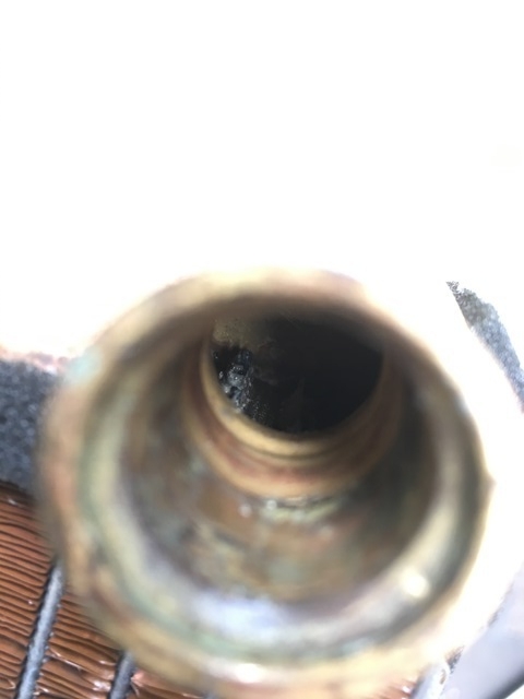
It turned out this thing isn't "growing" anything. It's all silicon!
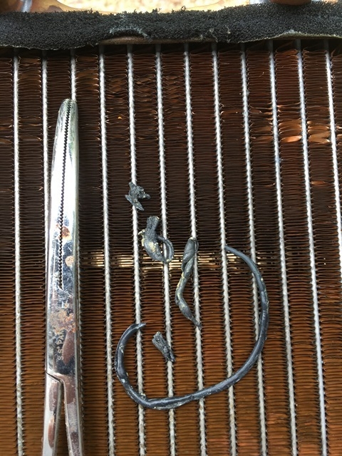
This wasn't even all of it... This stuff wasn't just packed in there either. It was actually inside the tubes. I didn't think it was going to stop coming out when I was pulling with a tweezers/pliers. I did have heat but it wasn't the best. Wierd huh? Needless to say the pressure flush before and after was drastically different. I have a feeling I'll be cooked out of that truck going forward Not sure where the silicone would have come from but I didn't do anything that would have knocked it loose.
Put the old core in and some of the ducting. Main x-member in too
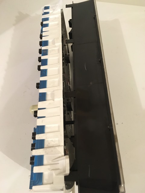
Last thing I did was the tach mod. Nothing new but here it goes. Pull the instrument panel out
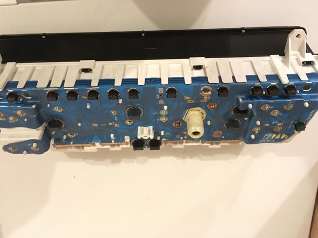
Slowly work your way down the panel and push in the black clips while pulling the 2 pieces apart
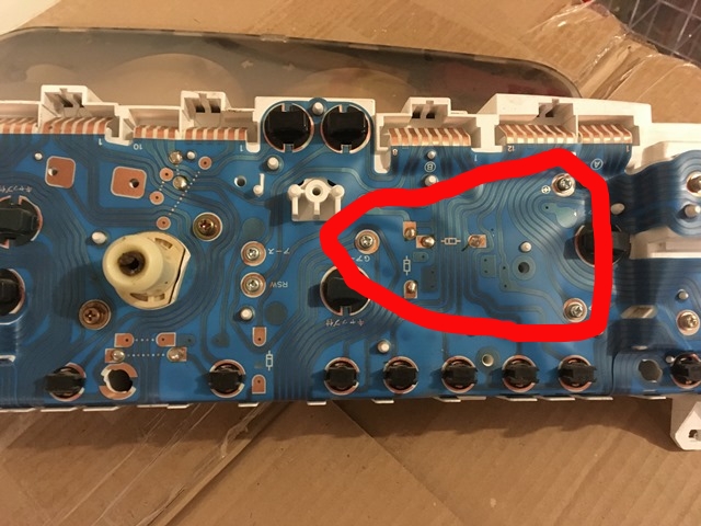
Remove these 3 screws
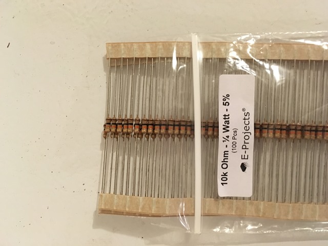
Bought my 10k resistors from Amazon. Did I need 100? No... But it was only a couple bucks more than buying individually. Plus I don't have to worry about screwing any bends up on the resistor. I have plenty of spares
Make your bends
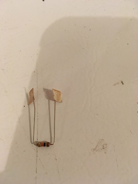
Cut resistor to length and begin. Left side was a bit messy... I was teaching my nephew how to solder. He did good though for his first time
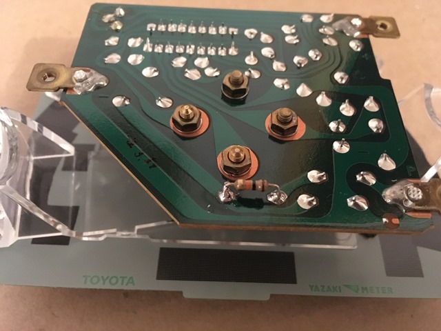
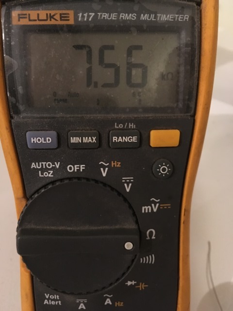
Good idea to test your resistance. The two resistors in parallel should yield around 7.67 kohm. With the 5% tolerance I'm good to go!
Slap it together and I'm on my way.
Before

After

I also did the steering column this way too. The before pic should be in a previous post I believe. It was pretty rusty but it basically wiped off with the acid...

For the sound deadening a guy could but a kit or the big names out there. I wanted to try and save some coin and go the DIY route. I bought some 1/8"x42"x72" EPDM/neoprene/SBR blend CCF on ebay. I then found some 4'x10' 1lb/sq ft MLV on amazon. I think the vendor was acoustic research on amazon. I also got Noico brand CLD off amazon too. I think this route was a huge money saver compared to the big box store for what I got.
Old deadener was hanging off the firewall when I removed the factor MLV mat.

Pulled the hanging junk off

CCF mocked up

MLV was cut the same way then some industrial strength Velcro strips placed in vertical places to help hold it. Cut out the CCF where the strips are at.

Busted out Noico and put it on the firewall. I bought the black foil

Still seemed "tingy" where I placed it... Maybe it'll help a bit. Better than nothing.

Hung my MLV/CCF mats up. This is half. Where there were bends I sliced it and then put a narrower strip over it to seal. I used HH-66 vinyl cement to bond the pieces. This goes for the CCF/MLV too.

Firewall fully covered. Yes those are pink safety glasses
I couldn't find mine so I used my niece's BB gun glasses 
And I put the factory deadener mat up with the cables redressed. If you go this route it will be tight! but worth it in my opinion...

Replaced the gaskets on the clutch/brake cylinders and the booster. For those interested here's the part numbers;

Hood hinge seals were blown. Replaced those

Steering shaft seal also blown

As a preventative measure I replaced the brake and clutch pedal plastic bushings

The winter before I ripped this apart the speedo cable began the 300 dB groan. The kind of sound that makes you think your truck is about to explode. Could have oiled the old one... But... It's easy right now to replace.

Problem is it has that extra hole and I no longer have an E-brake. I didn't have any rubber plugs laying around that would fit. I took some self fusing emergency tape and made a plug. I'm curious how long it holds up. I put two unpeeled pieces together and cut a circle that fit. Unpeeled the backing and plugged it up


I went to work on the heater core. I bought a replacement Spectra brand. May have seen on some of the dates on the Toyota parts packages they go back a ways. I'm a bit of a planner. I bought this heater core months ago. I didn't realize there was a separate copper tube for the inlet. I took a look at the galvanic series chart and copper and aluminum don't get along to well
I contactedSpectra thinking they would sell an aluminum tube... NOPE. So I'm going to make this old copper core work. I took a look inside and oh boy. On the inlet side it looks like the inside is growing some kind of grey fungus. I wished I would have taken a picture before I started cleaning. each tube had junk "growing" out of it. I pulled the big chunks out and here's a shot where a tube has a little bit left

It turned out this thing isn't "growing" anything. It's all silicon!

This wasn't even all of it... This stuff wasn't just packed in there either. It was actually inside the tubes. I didn't think it was going to stop coming out when I was pulling with a tweezers/pliers. I did have heat but it wasn't the best. Wierd huh?
Needless to say the pressure flush before and after was drastically different. I have a feeling I'll be cooked out of that truck going forward Not sure where the silicone would have come from but I didn't do anything that would have knocked it loose.Put the old core in and some of the ducting. Main x-member in too

Last thing I did was the tach mod. Nothing new but here it goes. Pull the instrument panel out

Slowly work your way down the panel and push in the black clips while pulling the 2 pieces apart

Remove these 3 screws

Bought my 10k resistors from Amazon. Did I need 100? No... But it was only a couple bucks more than buying individually. Plus I don't have to worry about screwing any bends up on the resistor. I have plenty of spares

Make your bends

Cut resistor to length and begin. Left side was a bit messy... I was teaching my nephew how to solder. He did good though for his first time

Good idea to test your resistance. The two resistors in parallel should yield around 7.67 kohm. With the 5% tolerance I'm good to go!

Slap it together and I'm on my way.
Last edited by duckhead; 08-27-2016 at 09:38 PM.
08-27-2016, 09:49 PM
#100
Registered User
Thread Starter
Join Date: Jun 2015
Location: WI
Posts: 147
Likes: 0
Received 0 Likes
on
0 Posts
Thanks again yota dude! I didn't have a choice. Not sure what the yards look like in your area but it's rough here. This was part of the selection at one of the yards
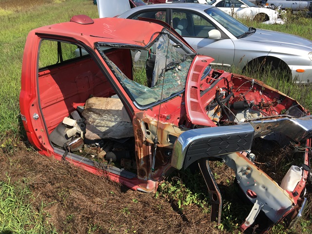
I just don't get it. They crush great vehicles but junk like this sits out there forever. There was another just like this one too.
I'm hoping so mbomberz! Appreciate that! Yah they're going to paint the doors next and the bed will be as is until Toyota Fiberglass can get me a new bed made. Right now it's a 2 year turn around time. He has the batch mix written down so he shouldn't have an issue remaking it. I'm hoping not anyway I should have just given up on finding different doors.
Haha! It's quite a journey rico! I don't have a whole lot of advice yet on your swap as I'm just now getting into mine. Hopefully my experience can help you out though!

I just don't get it. They crush great vehicles but junk like this sits out there forever. There was another just like this one too.
Great job on the whole thing, its going to be better than new when you are done. Should be a blast to drive around again!! Really fun to read through and follow along. So they are going to paint your parts at separate times? He was not worried about color matching at all?
I should have just given up on finding different doors.Haha! It's quite a journey rico! I don't have a whole lot of advice yet on your swap as I'm just now getting into mine. Hopefully my experience can help you out though!


