Vortec 3.5L I5 Swap 92 Pickup Ex Cab
 07-02-2014, 12:37 PM
#1
Registered User
Thread Starter

Join Date: Sep 2013
Location: Mission, BC
Posts: 70
Likes: 0
Received 0 Likes
on
0 Posts
Vortec 3.5L I5 Swap 92 Pickup Ex Cab
Well I started this in april sometime, since then I've gotten about 80% complete if you include all the extra stuff I may not do untill next winter. the engine is in and running, it's hooked up to the driveline and it hasent fallen onto my garage floor yet.
The Basic Setup pre engine swap:
-Toyota 92 Pickup V6 ex cab
-5 speed r150 trans & stock Tcase
-SAS done about a year ago
-Chevy rear spring swap done shortly after
-Open cariers front and back with 4.88 in the rear and 4.10 in the front
Post Swap:
-Vortec 3500, JTR steel header wired standalone with stock 3500 ecu from an automatic with auto codes removed.
-Air intake custom from butchered vortec air box (for the stock MAF) to silicone tubing to a home brew steel heatshield and intake mount, cheepo cone filter, on the port side of the engine bay right behind the headlight.
-Battery relocated to starboard side with a group 34 850 CCA battery
-JTR header modified right above the O2 sensor location, this required a redirect as the clearance between the block/bellhousing and Toy frame wouldn't allow for the fit hoever a simple cut and bend downard will make a crossover pipe below the belhousing/oil pan and above the front driveshaft possible, this is the main reason for the JTR header aside from price as you could order it in mild steel not yet ceramic coated for 350$ shipped.
-I havent made the crossover pipe yet, I will probly map it out and have a muffler shop bend it up for me.
-an earlier 4 cyl radiator that has successfully cooled my V6 for a year with no fan shroud is to be used, it has the same mounting location and the inlet and outlet coolant pipes line up with the vortec ones better. If it proves inadecuate I'll deal with it but from what I hear keeping these engeins cool is easy.
-R150 trans and transfercase, this attached to the stock MA5 bellhousing for this engine directly, no adapters required. a jeep AX15 input shaft is required to engage a machined bushing and jeep pilot bearing.
-Jeep cltuch kit joins this together with a slight modification of the pressure plate.
-I expected shimming to be required for the slave cylinder and pilot bearing (internal slave on the MA5) but so far without shimming engagement apears to be perfect. I expect the extra MA5 belhousing depth over the AX15 is taken up with a thicker flywheel.
- the engine is mounted back as far as I was comfortable with having no body lift givevn the trans tunnel clearances I ended up with more then enough room to mount electric fans on the engine side of the radiator if needed, the clutch fan would have been usable with the given depth if the steering box din't interfeer.
-the drivetrain moved backward about 5-6" the stock trans mount was modified for this and the trans it's self is about 1/2" lower then stock to allow for tunnnel clearance.
-front driveshaft was leangthened, I had a single piece rear driveshaft made up to elimnate the 2 piece and need for a carrier bearing, this is soemthing I was goign to do anyway.
-rear diff will be rebuilt with supra LSD module after initial testing and I decide on the gear ratio I want to go with. I expect given the power and a 33-35" tire I'll be happiest with a 4.10 ratio for econemy and torque, I'll not be doing any rock climing.
-I'll likely just weld the front if I can't find a cheap spool.
-while a 40 pulse GM VSS is not really required to make this run properly it will help with hiway fuel econemy, the ecu goes into a leaner cruise mode, from what I've read this will improve about hiway fuel econemy about 10% if I can supply a GM VSS signal to the computer.
-There are products that will replace the Toy gear driven VSS with a 40 pulse GM one but I want to maintain the Toy speedo and antilock brake controls so I'll be cereating a driveshaft flange mounted reluctor disk and stock GM VSS mounted right above the Tcase ouput shaft, there is a diff mounted product from JTR but it's not quite what I want and looks vulnerable to damage.
-Dirt and grim should not effect the fucntion of these sensors as they are hall effect and work of the magnetic field disruption of a reluctor wheel, this could be caked in mud and oil and still work perfectly fine, they work on the same principal as ABS wheel sensors. My plan is to cut a 40 tooth wheel and embed it in a high strength platic, 1/4" HDPE or UHMW, this will protect the sensor under impact and keep the teeth from grabing anything unwanted, plastic will not interfear with the field disruption of the ferus metal disk.
-Engine mounted about as high as possible, there is about 1-2" clearance over the engine to the hood, this gives me a ton of room under the oil pan to the diff and steering rods, these are tall engines and I don't know if this would be possible without the SAS.
-Mounts were custom fabricated, the existing toy mount bosses were removed and the box they mount on was copped up, 1/4" plate was used and welded into those boxes and guseted about as much as possible creating a samwich plate onto the stock GM motor mounts mounted with a high grade 1/2" through bolt.
Things yet to figure out:
-where to mount all the A/C crap I want to put in, the dash controls and heater core swapouts are easy but all the other junk will be tricky added along with the electric fans I want to push on the rad from the outside and custom lines
-I'm not sure how yet to get proper oil pressure and coolant heat readings to the existing dash guages. I know this data is sent to the computer but translating that to an an analog signal for the existing guages is soemthing else. the fans will be on a thermostat style switch at 180 deg F.
-the exauhst crossover pipe
-modifing the shifter locations insdie
-I want beter seats
-I need to get a line made up to go from the P/S box to the box on the high pressure side, this shoudln't be an issue I just haven't done it yet.
-front fenders were rusted out so I replaced them with some nice rust free lime green specemins, I'll be doing a paint job in a wall tent in my driveway at some point but this isnt a prioirty for me.
All minor really, once I bolt up my driveshafts I can pretty much drive it around as is, more to come with pictures ......
 07-02-2014, 07:46 PM
#2
Registered User
Join Date: Jan 2012
Posts: 151
Likes: 0
Received 0 Likes
on
0 Posts
Sounds like a cool swap , post some pics when you can .
On my 4.3 swap for the gauges I drilled and tapped for a Toyota temp sensor next to the gm sensor in the intake manifold . For the oil pressure sensor I put a tee fitting and ran a gm for the computer and a toy for the gauge . Buy a factory Toyota chassis wiring manual from eBay . Mine was $30 like new . It will tell you which plug wires to tap into for the gauges by the passenger kick panel .
On my 4.3 swap for the gauges I drilled and tapped for a Toyota temp sensor next to the gm sensor in the intake manifold . For the oil pressure sensor I put a tee fitting and ran a gm for the computer and a toy for the gauge . Buy a factory Toyota chassis wiring manual from eBay . Mine was $30 like new . It will tell you which plug wires to tap into for the gauges by the passenger kick panel .
07-03-2014, 07:39 AM
#3
Registered User
Thread Starter
Join Date: Sep 2013
Location: Mission, BC
Posts: 70
Likes: 0
Received 0 Likes
on
0 Posts
Both good ideas, truthfully I haven't given that much thought yet, I've just been pluging away here and there, for anyone considering this engein for use do yourself a favour and leave seom meat on the high pressure power steering line if you're going to cut it, I've been having a real bitch of a time finding a fitting to match up.
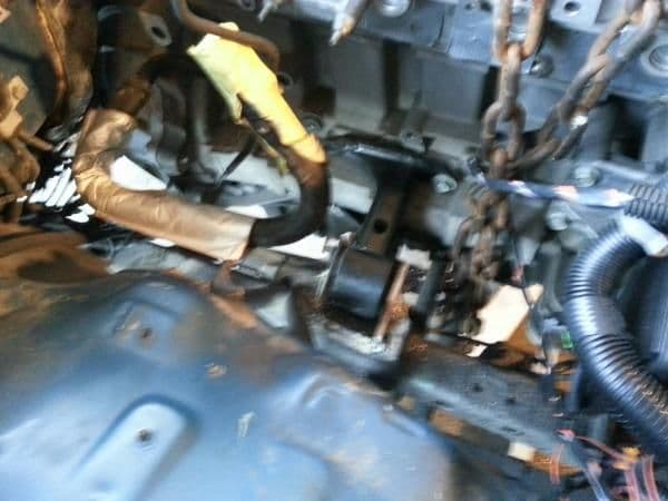
A Blurry Pic of the engein sitting in place mocked up, these are older pictures of my fist install an mockup for the mounts, it eventually comes out and gets welded up properly.
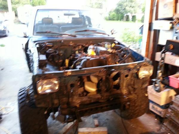
Exauhst side
A Blurry Pic of the engein sitting in place mocked up, these are older pictures of my fist install an mockup for the mounts, it eventually comes out and gets welded up properly.
Exauhst side
 07-03-2014, 07:46 AM
#6
Registered User
Thread Starter
Join Date: Sep 2013
Location: Mission, BC
Posts: 70
Likes: 0
Received 0 Likes
on
0 Posts
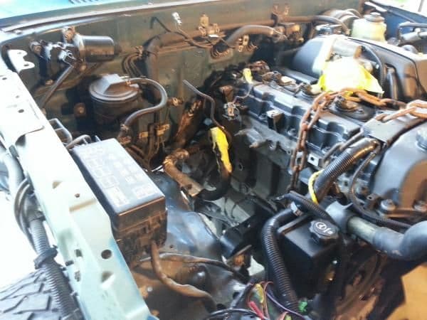
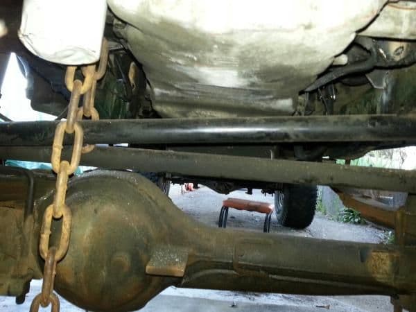
"are you going to have enough room for a radiator? I have swapped a long motor before and can give some ideas how to mount it."
No pic of that at the moment but with no clutch fan and the rad mounted I have about 4" clear from the accessory belt and pullies to the rad
closer up pic of the exuahst side mount
mounted about as high as I coudl get it
No pic of that at the moment but with no clutch fan and the rad mounted I have about 4" clear from the accessory belt and pullies to the rad
closer up pic of the exuahst side mount
mounted about as high as I coudl get it
Trending Topics
07-03-2014, 07:54 AM
#8
Registered User
Thread Starter
Join Date: Sep 2013
Location: Mission, BC
Posts: 70
Likes: 0
Received 0 Likes
on
0 Posts
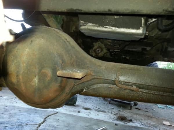
reluctor wheel for driveshaft flange mounting
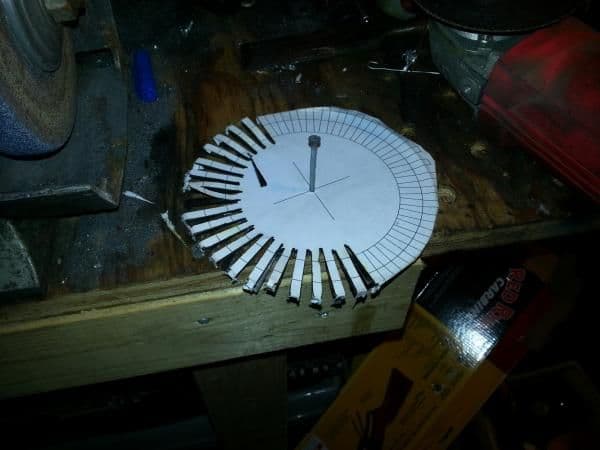
This was a first try I'm going to do another one, these teeth are cut to deep for the flange bolts. I'll then heat it up and press it inot a slightly larger piece of 1/4" UHMW.
It don't need to be pretty but it does need to create a magnetic field disruption and the subsequent 40 pulse signal.
This was a first try I'm going to do another one, these teeth are cut to deep for the flange bolts. I'll then heat it up and press it inot a slightly larger piece of 1/4" UHMW.
It don't need to be pretty but it does need to create a magnetic field disruption and the subsequent 40 pulse signal.
07-03-2014, 07:58 AM
#9
Registered User
Thread Starter
Join Date: Sep 2013
Location: Mission, BC
Posts: 70
Likes: 0
Received 0 Likes
on
0 Posts
If you had a mild body lift and mountd this another couple inches back I'm sure you could stuff the 4.2L inline 6 in there. as it sits there is just enough room for the clutch fan and rad but the clutch fan is mounted prety far drivers side and would hit the power steering box.
If anyone is curious about anything in particular let me know I'll take a pic.
More pictures to come.....

If anyone is curious about anything in particular let me know I'll take a pic.
More pictures to come.....
Last edited by 92yota92; 07-03-2014 at 09:31 AM.
07-04-2014, 07:34 AM
#10
Registered User
Thread Starter
Join Date: Sep 2013
Location: Mission, BC
Posts: 70
Likes: 0
Received 0 Likes
on
0 Posts
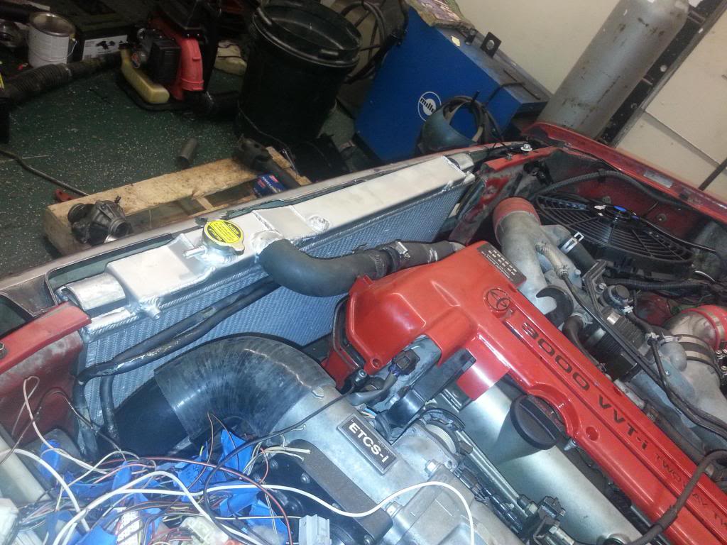
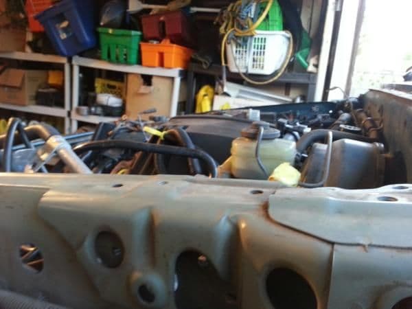
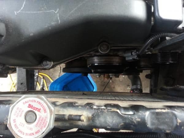
Taken Last night, it's a bit cleaner these days

My plan is to find or make smaller coolant overflo and washer fluid bottles and bolt them to the side of the intake heat shield.
clearance to the rad
My plan is to find or make smaller coolant overflo and washer fluid bottles and bolt them to the side of the intake heat shield.
clearance to the rad
Last edited by 92yota92; 07-04-2014 at 07:36 AM.
07-04-2014, 07:39 AM
#11
Registered User
Thread Starter
Join Date: Sep 2013
Location: Mission, BC
Posts: 70
Likes: 0
Received 0 Likes
on
0 Posts
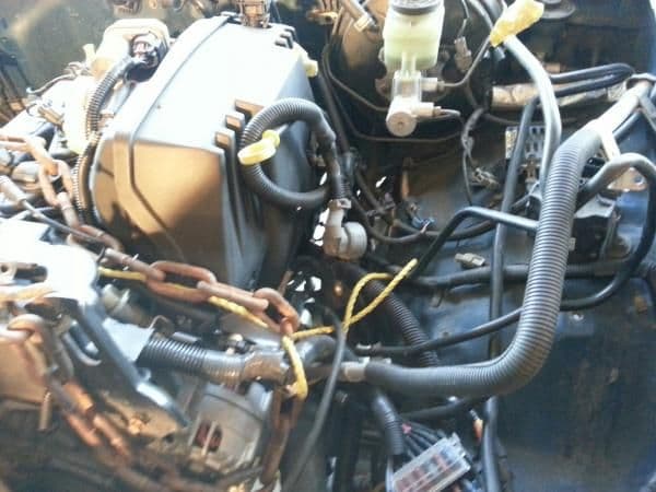
I have an idea to mount the a/c rad/condensor whatever the crap it is on the inside of the coolant rad but I'm not sure how this will effect things, I could then run 2 electric push fans on the outside.
Note the spark plug sticking out of the bottom of my rad, I can't find my rad plug anywhere .......
Note the spark plug sticking out of the bottom of my rad, I can't find my rad plug anywhere .......
Last edited by 92yota92; 07-04-2014 at 08:36 AM.
07-11-2014, 09:35 AM
#12
Registered User
Sweet build!! Im currently building a 87 truck with 4.3mpi. So your reluctor ring is for the engine or vss?? Just curious.Looks killer in the engine bay!!
07-11-2014, 10:26 AM
#13
Registered User
Thread Starter
Join Date: Sep 2013
Location: Mission, BC
Posts: 70
Likes: 0
Received 0 Likes
on
0 Posts
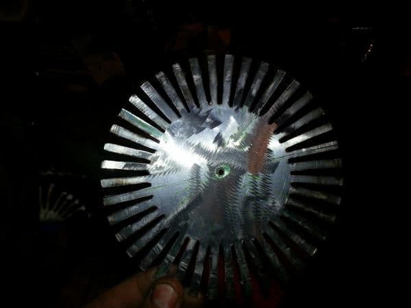
Ya the home made reluctor ring will provide the magnetic field disruption to a standard GM sensor which will feed the GM ECU. I wanted to maintain the Toy VSS for the existing stystems. There is a product you can buy from Jags that run that is a diff mounted vesion of this and it's where I got the idea.
I opted to put it on the tcase output rather then the diff as the diff mounted one from JTR looks vulnerable to 4x4 hazards and being on the tcase and up in the trans tunnel would be a little more protected, I also plan to have this thing embeded into a UHMW sheet to protect it from impacts and if it were to get impacted and bend into the sensor the teeth woudnt be able to grab and just skip off instead.
UHMW metling point is fairly low so just heating the plate up with a torch and pressing it into a 1/4" sheet should fo the trick.
07-13-2014, 09:17 AM
#14
Registered User
Thread Starter
Join Date: Sep 2013
Location: Mission, BC
Posts: 70
Likes: 0
Received 0 Likes
on
0 Posts
Sounds like a cool swap , post some pics when you can .
On my 4.3 swap for the gauges I drilled and tapped for a Toyota temp sensor next to the gm sensor in the intake manifold . For the oil pressure sensor I put a tee fitting and ran a gm for the computer and a toy for the gauge . Buy a factory Toyota chassis wiring manual from eBay . Mine was $30 like new . It will tell you which plug wires to tap into for the gauges by the passenger kick panel .
On my 4.3 swap for the gauges I drilled and tapped for a Toyota temp sensor next to the gm sensor in the intake manifold . For the oil pressure sensor I put a tee fitting and ran a gm for the computer and a toy for the gauge . Buy a factory Toyota chassis wiring manual from eBay . Mine was $30 like new . It will tell you which plug wires to tap into for the gauges by the passenger kick panel .
There's a built in Tee over the oil filter specifically for an after market gauge sender so that's convenient, I've already in the temp sensor up on the coolant outlet pipe, that should get me close enough for a good reading and it was easy to get too.
07-17-2014, 08:24 AM
#16
Registered User
Thread Starter
Join Date: Sep 2013
Location: Mission, BC
Posts: 70
Likes: 0
Received 0 Likes
on
0 Posts
now I need to figure ourt how to generate a tach signal, and yes I'd like to use the stock cluster tach.
The toy (I'm almsot sure) takes a singal from the coil before the distributer so it's making pulse every 4 revs 6 times so 6/4 per rev unless there's a waist spark system in play.
The I5 is coil over plug and can use a singal from any 1 coil or any 1 injector and should make a signal 1/4 per rev.
So now how do I make 1/4 = 6/4?
07-17-2014, 12:03 PM
#17
Registered User
Thread Starter
Join Date: Sep 2013
Location: Mission, BC
Posts: 70
Likes: 0
Received 0 Likes
on
0 Posts
Well to awnser my own question, for those interested, it should be a simple matter of replacing the 10k ohm resistor on the tach circut board with a 1.7k ohm resistor then I can draw the pulse from either a coil or an injector and hook it up to the body harness pin for the tach.
07-18-2014, 07:35 AM
#18
Registered User
Thread Starter
Join Date: Sep 2013
Location: Mission, BC
Posts: 70
Likes: 0
Received 0 Likes
on
0 Posts
Ran the truck for a good couple minutes last night to get it up to temp, all my guages work except for the tach (a work in progress) and nothing leaks a drop, aside from my rad (since I can't find my rad plug I've been using a spark plug) it drips a bit. I'm going to switch my electric fan to a puller so I can mount an A/c condensor on the outside with it's own pusher fan, after that it's on the road!
Well on the road to a muffler shop so I can get the intermediate piece made from my header to the cat back section. I was going to make this myself but I don't have a bender and pre bend pieces add up in cost, not to mention the flanges, I tihnk it'll be cheaper this way.
Well on the road to a muffler shop so I can get the intermediate piece made from my header to the cat back section. I was going to make this myself but I don't have a bender and pre bend pieces add up in cost, not to mention the flanges, I tihnk it'll be cheaper this way.
07-18-2014, 12:51 PM
#19
Registered User
Thread Starter
Join Date: Sep 2013
Location: Mission, BC
Posts: 70
Likes: 0
Received 0 Likes
on
0 Posts
Picked up a rad drain plug some electrical connectors and a nice intact slide out drink tray from the wrecker today at lunch, also found an a/c condensor that is a bit thinner and in better shape the the toyota one I found a while back, I think it's form a honda of some sort, it was already yanked just sitting there waiting for me shinning in the sun.
I have to have custom lines mde up since the compressor is on the drivers side on this engine, if the a/c was passenger side and the p/s pump were drivers side like it should be then my life would have been a bit easier.
So miss matched connectors don't worry me much.
I have to have custom lines mde up since the compressor is on the drivers side on this engine, if the a/c was passenger side and the p/s pump were drivers side like it should be then my life would have been a bit easier.
So miss matched connectors don't worry me much.
07-25-2014, 07:21 AM
#20
Registered User
Thread Starter
Join Date: Sep 2013
Location: Mission, BC
Posts: 70
Likes: 0
Received 0 Likes
on
0 Posts
I've been drivning it around for a solid week now with no major issues, still no speedo or tach, this is a special isntall so the cluster harnesses are almost completely unplugged and I'm thinking there must be some main power running through it that I need to hook up in order to get them to work.
Lots of power it hard to describe, hard to get traction in the rain actually lots of torque downlow, I'm waiting on my LSD install untill I decide what tire size gear ratio I'm going to go with. Hard to estimate fuel econemy with no odomiter but I would say I'm getting about 12l per 100km which is a vast improvlemtn over the v6.
Lots of power it hard to describe, hard to get traction in the rain actually lots of torque downlow, I'm waiting on my LSD install untill I decide what tire size gear ratio I'm going to go with. Hard to estimate fuel econemy with no odomiter but I would say I'm getting about 12l per 100km which is a vast improvlemtn over the v6.


