Composite Winch Mount Bumper - Senior Design Project
 02-27-2008, 12:45 PM
#21
Registered User
Thread Starter
Join Date: Jun 2005
Location: Minnesota
Posts: 378
Likes: 0
Received 0 Likes
on
0 Posts
Thanks for the input! I share your concern with the bolts pulling out and I plan on making an aluminum spacer to act as a washer for the mounting points. The 'fraying' that occurs is a result of the matrix (resin) cracking and failing before the fibers (which are much stronger in their axial direction), fail.
Bumping and scraping is a concern too, but the proposed fiberglass shell should cover the outside of most of the structural section and will hopefully take most of the beating. Another option might be to put a layer or two of fiberglass over the carbon part to protect the carbon from wear and tear.
I have not used ANSYS, but my school uses NASTRAN/FEMAP and SolidWorks as their software package. I am currently in an FEA class, and as soon as we get to solid elements (we are doing beam elements now) I plan on running an analysis of the structural part.
This probably isn't something you would want to use for real hardcore off-roading, but as far as I know of it may be the first of its kind, so who knows?
 02-27-2008, 01:06 PM
#22
Contributing Member
What if you fabricated some plates out of aluminum for the hardest hit areas of the bumper?
Leading front edge, maybe corners.
I don't know if you'd glue them on or drill holed and mount them with bolts.
Like you said, your bumpers primary design isn't to do direct battle with the rocks, but was wondering if you could beef it up if needed. Could even make the plates removable/ replaceable perhaps.
02-27-2008, 02:25 PM
#23
Registered User
Thread Starter
Join Date: Jun 2005
Location: Minnesota
Posts: 378
Likes: 0
Received 0 Likes
on
0 Posts
Elvota, that is not a bad idea. I would probably be a better idea to epoxy the edge reinforcements on rather than bolting them because drilling holes in composite can weaken it. Even epoxied on, the aluminum would help distribute an impact load.
02-27-2008, 02:45 PM
#24
Registered User
Thread Starter
Join Date: Jun 2005
Location: Minnesota
Posts: 378
Likes: 0
Received 0 Likes
on
0 Posts
Progress update!
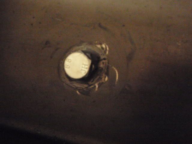
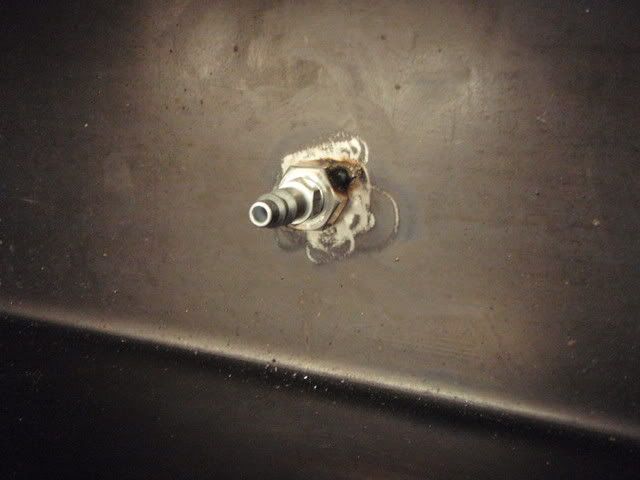
Today we drilled a hole in the top surface and welded a nut to the inside of the tooling. A bolt was specially machined to fit the hole very tight and flush for when the part is being laid up and processed. After the part is cured, this bolt can be removed and an air fitting threaded in so that compressed air can be used to pop the part off of the tooling.
Outside view

Plug installed (outside view)

Inside view: plug installed
Inside view: air fitting installed
My winch is scheduled to arrive in the mail tomorrow, so with that in hand I have made a goal to have a prototype made and mounted by the end of next week! This wont be a full-strength unit, but rather will probably just be 8-10 plies fiberglass to make sure that the part will come off of the tooling and to make sure that everything fits when bolted up.
I am very excited for this, and it should be a productive spring break coming up!
Today we drilled a hole in the top surface and welded a nut to the inside of the tooling. A bolt was specially machined to fit the hole very tight and flush for when the part is being laid up and processed. After the part is cured, this bolt can be removed and an air fitting threaded in so that compressed air can be used to pop the part off of the tooling.
Outside view
Plug installed (outside view)
Inside view: plug installed
Inside view: air fitting installed
My winch is scheduled to arrive in the mail tomorrow, so with that in hand I have made a goal to have a prototype made and mounted by the end of next week! This wont be a full-strength unit, but rather will probably just be 8-10 plies fiberglass to make sure that the part will come off of the tooling and to make sure that everything fits when bolted up.
I am very excited for this, and it should be a productive spring break coming up!
02-27-2008, 02:49 PM
#25
Contributing Member
Join Date: Nov 2007
Location: Indiana
Posts: 776
Likes: 0
Received 0 Likes
on
0 Posts
Some good input on here. I think if all the guys on yotatech put there heads together we could build the greatest offroad machine the world had ever seen with the coolest parts. I love the idea of the composite bumber. Cant wait to see what the final product looks like. I was also thinking, like Elvota but he beat me to it that it would be a good idea to put aluminum or somthing in the high impact areas. Great work so far. Looks like your senior design project is going much better than mine did. Oh it was a disaster. Not entirely our fault. Got an A but it was stressfull.
02-28-2008, 05:51 PM
#27
Registered User
Might want to Use steel instead of aluminum on your mounting locations, if those locations are incontact with carbon fiber, As carbon fiber and Aluminum do not get along well and tend to break each other down.
02-29-2008, 10:56 AM
#28
Registered User
Join Date: Apr 2003
Location: Juneau, Alaska
Posts: 991
Likes: 0
Received 0 Likes
on
0 Posts
Erich
02-29-2008, 03:02 PM
#29
Registered User

Join Date: Feb 2008
Location: Ventura, CA
Posts: 6
Likes: 0
Received 0 Likes
on
0 Posts
Looking in my corrosion book graphite is about as noble as you can get in Potential and Aluminum is pretty damn reactive so I guess you are right. If you aluminum is anodized or chem filmed, this should help out quite a bit.
Titanium and Aluminum is another bad combo
03-02-2008, 12:40 AM
#30
Registered User
yes it is, btw from what ive read anodized aluminum in carbon layups is one way of solving it the other was to use a layer of glass between the carbon and aluminum
03-03-2008, 11:00 AM
#31
Registered User
Join Date: Apr 2003
Location: Juneau, Alaska
Posts: 991
Likes: 0
Received 0 Likes
on
0 Posts
As long as you have a good layer of adhesive you shouldn't have a problem. Also if the layup is done correctly there should be minimal carbon-to-aluminum contact anyway because of the resin.
Looking in my corrosion book graphite is about as noble as you can get in Potential and Aluminum is pretty damn reactive so I guess you are right. If you aluminum is anodized or chem filmed, this should help out quite a bit.
Titanium and Aluminum is another bad combo
Looking in my corrosion book graphite is about as noble as you can get in Potential and Aluminum is pretty damn reactive so I guess you are right. If you aluminum is anodized or chem filmed, this should help out quite a bit.
Titanium and Aluminum is another bad combo
 Anodized aluminum plates on a carbon fiber bumper just sounds cooler anyway!
Erich
 03-12-2008, 04:54 PM
#33
Registered User
Thread Starter
Join Date: Jun 2005
Location: Minnesota
Posts: 378
Likes: 0
Received 0 Likes
on
0 Posts
Actually quite a bit of progress! We got a prototype made last week, but I have been pretty busy with other stuff lately. I will have a writeup and pictures up soon!
03-15-2008, 08:56 AM
#34
Registered User
Thread Starter
Join Date: Jun 2005
Location: Minnesota
Posts: 378
Likes: 0
Received 0 Likes
on
0 Posts
FINALLY! I have some spare time to post up our progress! Last week was very busy as you will see in the following pictures.
First: The good people at Smittybilt were kind enough to donate an XRC-8 winch to our design team! A BIG thanks to them!
To make the spool control more accessible in the bumper, I removed the transmission section of the winch and by removing the 10 small allen screws was able to clock the housing a few degrees.

Next Episode: Prototype construction
First: The good people at Smittybilt were kind enough to donate an XRC-8 winch to our design team! A BIG thanks to them!
To make the spool control more accessible in the bumper, I removed the transmission section of the winch and by removing the 10 small allen screws was able to clock the housing a few degrees.
Next Episode: Prototype construction
03-15-2008, 09:11 AM
#35
Registered User
Thread Starter
Join Date: Jun 2005
Location: Minnesota
Posts: 378
Likes: 0
Received 0 Likes
on
0 Posts
Last week over spring break I stuck around campus and completed the prototype for our support section. This prototype was made of a thin 10 layers of fiberglass prepreg. Prior to layup, we coated the steel tooling with a special polymer mold release to allow the part to come off the tool once cured.
We began the layup with 10 plies of a reinforcing strip, and then alternated between two different patterns (5 plies each) to obtain the necessary thickness. The following picture shows the reinforcing strips applied under the first main layer.
Once all of the plies were applied, thin steel caul plates were attached to help give a smooth finish on the outside surfaces.

Next, the part was vacuum bagged and was made ready to go in the autoclave (basically a big pressure cooker).

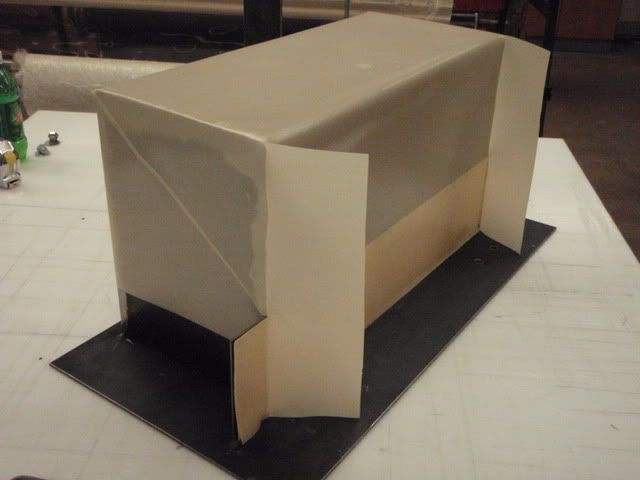
After the part cured and the processing materials were removed, this is what we got:

We used the previously installed air fitting on the tool to pop the part off about 4 inches, but this was not enough. It was determined that we may not have incorporated quite enough draft into the tooling to allow it to come off easily, and our solution to this will be shown in a future post. In the meantime, to get this part off we had to slit one of the corners a few inches,and here is the resulting part:

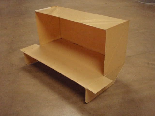
Being only 10 plies thick (about 0.1"), the part is fairly flimsy and has a feel similar to cardboard. Holes were then drilled both to mount it to the truck and to the winch, and here is the result:

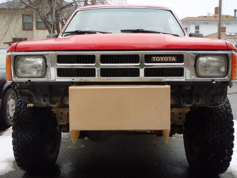

And finally, with the winch installed:
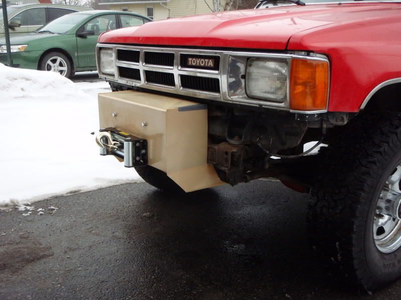
We were all surprised that such a flimsy structure was able to hold such a heavy winch on its own. Once it was bolted up to the truck's frame, it really stiffened up the whole part and made it quite strong. ']
Next episode: tooling modifications
We began the layup with 10 plies of a reinforcing strip, and then alternated between two different patterns (5 plies each) to obtain the necessary thickness. The following picture shows the reinforcing strips applied under the first main layer.
Once all of the plies were applied, thin steel caul plates were attached to help give a smooth finish on the outside surfaces.
Next, the part was vacuum bagged and was made ready to go in the autoclave (basically a big pressure cooker).
After the part cured and the processing materials were removed, this is what we got:
We used the previously installed air fitting on the tool to pop the part off about 4 inches, but this was not enough. It was determined that we may not have incorporated quite enough draft into the tooling to allow it to come off easily, and our solution to this will be shown in a future post. In the meantime, to get this part off we had to slit one of the corners a few inches,and here is the resulting part:
Being only 10 plies thick (about 0.1"), the part is fairly flimsy and has a feel similar to cardboard. Holes were then drilled both to mount it to the truck and to the winch, and here is the result:
And finally, with the winch installed:
We were all surprised that such a flimsy structure was able to hold such a heavy winch on its own. Once it was bolted up to the truck's frame, it really stiffened up the whole part and made it quite strong. ']
Next episode: tooling modifications
03-28-2008, 07:32 AM
#38
Registered User
Thread Starter
Join Date: Jun 2005
Location: Minnesota
Posts: 378
Likes: 0
Received 0 Likes
on
0 Posts
I have made changes to the tooling to allow for more of a draft angle, but I dont have any good pics to post up at this point. The top edge of the part has been sloped by about 3/8".
I have also begun the construction of a test fixture to attach the next carbon fiber prototype to an Instron test machine to evaluate its tensile strength. More pics will come!
I have also begun the construction of a test fixture to attach the next carbon fiber prototype to an Instron test machine to evaluate its tensile strength. More pics will come!


