jmazos's 84 pickup buildup.
 02-15-2008, 03:26 PM
#1
Contributing Member
Thread Starter
Join Date: Sep 2007
Location: St. Geroge, Utah
Posts: 137
Likes: 0
Received 0 Likes
on
0 Posts
jmazoso's 84 pickup buildup.
I'm starting a thread for my mods and stuff.
Got photos of a few of my past projects that I will post over the next week or so.

Here's what just came in the UPS
Got photos of a few of my past projects that I will post over the next week or so.
- 1" wabfab body lift -- thanks brian
- IFS brake conversion
- extended diff breathers
- custom rock sliders
Here's what just came in the UPS
Last edited by jmazoso; 04-14-2008 at 08:37 AM. Reason: can't spell

 02-20-2008, 11:12 AM
#3
Contributing Member
Thread Starter
Join Date: Sep 2007
Location: St. Geroge, Utah
Posts: 137
Likes: 0
Received 0 Likes
on
0 Posts
So my dual cases are coming along. Had to tear both cases apart cause I have a remote shift box in the truck now. Just got my driveshaft back from SixStates in St. George. I'll post a pic of it later, they did a sweet job. Picked up tubing for a square drive shaft from Interstate Steel.
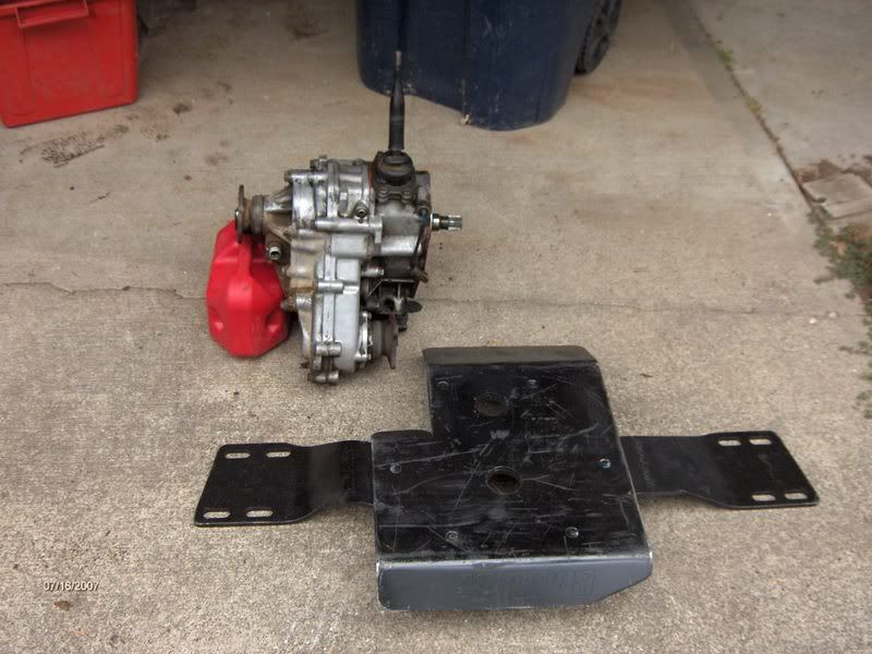
Here's a couple of pics of my slider buildup. I lost a bunch of progress pics from the installation due to a camera error.
Main slider unit. I've got hoops to cover the bedsides.

Fish plate on the frame (bad photo)

My carb works ok, but just ok.
Here's a link I found about building square driveshafts. Seems pretty through.
http://www.rocketcityrockcrawlers.co...%20Project.pdf
Here's a couple of pics of my slider buildup. I lost a bunch of progress pics from the installation due to a camera error.
Main slider unit. I've got hoops to cover the bedsides.
Fish plate on the frame (bad photo)
My carb works ok, but just ok.
Here's a link I found about building square driveshafts. Seems pretty through.
http://www.rocketcityrockcrawlers.co...%20Project.pdf
Last edited by jmazoso; 02-20-2008 at 11:14 AM.
02-20-2008, 11:47 AM
#4
Contributing Member
Thread Starter
Join Date: Sep 2007
Location: St. Geroge, Utah
Posts: 137
Likes: 0
Received 0 Likes
on
0 Posts
Driveshaft pics

Detail of the weld. Pretty dang nice weld.

Less than 70 bucks for cutting it down, welding, balanceing, and 2 new joints.
Detail of the weld. Pretty dang nice weld.
Less than 70 bucks for cutting it down, welding, balanceing, and 2 new joints.
02-25-2008, 10:57 AM
#5
Contributing Member
Thread Starter
Join Date: Sep 2007
Location: St. Geroge, Utah
Posts: 137
Likes: 0
Received 0 Likes
on
0 Posts
Here's 2 more shots of my sliders. Got them all on and painted.


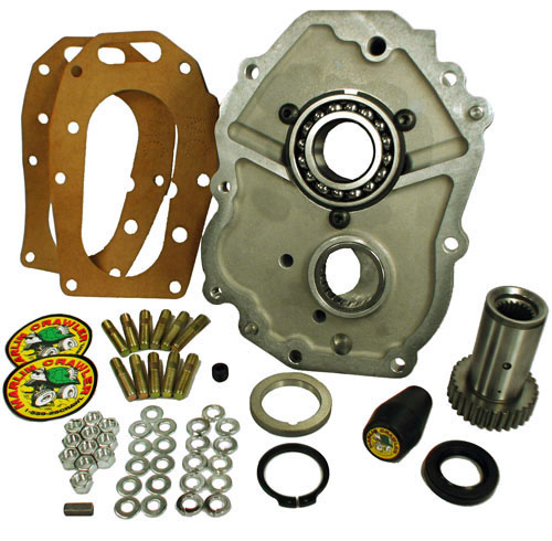
Followed the instruction from Marlin's web page to put in my clocked dual case adaptor. Turns out that I had both of the exceptions isted. My original case was a remote shifter, so it had to go in front. The other issue is the donor was out of an 80, so I had to grind on the input shaft to get things to go together. Here's a close-up of the input shaft after grinding. This is a big photos, but I couldn't find a good one of how much to grind off. This was enough, and the cases went right together.

Well it ran on its own power. Still need to build the front driveline, and get some interior work done. Planning to get it buttoned up to go out for a while on Saturday.
Followed the instruction from Marlin's web page to put in my clocked dual case adaptor. Turns out that I had both of the exceptions isted. My original case was a remote shifter, so it had to go in front. The other issue is the donor was out of an 80, so I had to grind on the input shaft to get things to go together. Here's a close-up of the input shaft after grinding. This is a big photos, but I couldn't find a good one of how much to grind off. This was enough, and the cases went right together.
Well it ran on its own power. Still need to build the front driveline, and get some interior work done. Planning to get it buttoned up to go out for a while on Saturday.
 02-25-2008, 01:43 PM
#7
Contributing Member
Thread Starter
Join Date: Sep 2007
Location: St. Geroge, Utah
Posts: 137
Likes: 0
Received 0 Likes
on
0 Posts
I ordered rotors from Brian at Wabfab. Got a set of new Dorman studs from the Checker down the street. Not really too much too it. It's worth doing your bearings at the same time, you've got it all torn apart anyway. You will likely need 1" wheel spacers to clear the bigger calipers. Brian has those too. The dust cover will either have to be trimmed or removed. I just took mine off. You can do it all in an afternoon once you get parts. The studs can be a pain to get into the hub. Use some anti-seize and the flat face of a nut, and they should pull through. The new brakes work good, but I do want to get a larger master cylider in the future.
Trending Topics
02-28-2008, 07:38 AM
#8
Contributing Member
Thread Starter
Join Date: Sep 2007
Location: St. Geroge, Utah
Posts: 137
Likes: 0
Received 0 Likes
on
0 Posts
Square Front Driveshaft Build
So I buillt my square front driveshaft last night. Took us 3 hours including eating dinner and BSing with the neighbor. Found out that he has a JLG tube bender in his garage. 
Here's the stock front driveline. I was 26 inches. With the dual cases, I had to add 6 5/8 inches, which is what I had the rear driveline cut down, and it fit perfectly.

Cut off the splined end of the yoke end leaving about 1 inch. My tubes were receiver hitch stock. The end of the splined shaft fit in the inner tube with a little grinding on four sides. Go slow with your grinding, you want a snug fit.

Here's Jeremy cutting down the hollow end of the shaft with the Rigid chop saw.

The yoke end of the shaft welded on to the inner tube.

Welding on the shaft. Thought that the picture turned out pretty cool.

Here's the finished weld on the CV end of the shaft. I did the welding with a Millermatic 175, with .035 flux-core wire. We used up the last of the gas last week and have not yet gotten the bottle filled. Ran the welder farily hot. Got great penetration, and nice looking welds.

Used a peice of flat stock to cap the end of the inner shaft. I had planned to put some sand in the inner shaft, but I forgot to cap the yoke end of the shaft, so I'm SOL on that plan, but they work without it.
Tapped the out shaft for a zerk. Bought a cheap tap set from Checker. Stay away from them. The chuck wont hold the tap unless you wack it on with a hammer. Even though it only cost $7.99 for the set, I got ripped off.
Here's the shaft at the end of fabrication. In my current configuration, I will have 4 inches of compression and about 12 inches of extention. Tubes fit really well, not much play, even without the grease in it yet.

I am going to clean it up and paint the whole thing today. Then grease it up and install it tonight. Planning to go out an wheel it on Saturday.
Here's the stock front driveline. I was 26 inches. With the dual cases, I had to add 6 5/8 inches, which is what I had the rear driveline cut down, and it fit perfectly.
Cut off the splined end of the yoke end leaving about 1 inch. My tubes were receiver hitch stock. The end of the splined shaft fit in the inner tube with a little grinding on four sides. Go slow with your grinding, you want a snug fit.
Here's Jeremy cutting down the hollow end of the shaft with the Rigid chop saw.
The yoke end of the shaft welded on to the inner tube.
Welding on the shaft. Thought that the picture turned out pretty cool.
Here's the finished weld on the CV end of the shaft. I did the welding with a Millermatic 175, with .035 flux-core wire. We used up the last of the gas last week and have not yet gotten the bottle filled. Ran the welder farily hot. Got great penetration, and nice looking welds.
Used a peice of flat stock to cap the end of the inner shaft. I had planned to put some sand in the inner shaft, but I forgot to cap the yoke end of the shaft, so I'm SOL on that plan, but they work without it.
Tapped the out shaft for a zerk. Bought a cheap tap set from Checker. Stay away from them. The chuck wont hold the tap unless you wack it on with a hammer. Even though it only cost $7.99 for the set, I got ripped off.
Here's the shaft at the end of fabrication. In my current configuration, I will have 4 inches of compression and about 12 inches of extention. Tubes fit really well, not much play, even without the grease in it yet.
I am going to clean it up and paint the whole thing today. Then grease it up and install it tonight. Planning to go out an wheel it on Saturday.
03-03-2008, 12:02 PM
#9
Contributing Member
Thread Starter
Join Date: Sep 2007
Location: St. Geroge, Utah
Posts: 137
Likes: 0
Received 0 Likes
on
0 Posts
Had the truck out on Saturday. It rocked. Went out and did Upper Sliplock (I think?) on the West Rim. Crawlers are cool. I really love having 2lo.
Learned a couple of things. My stock carb is fine, didn't stall out because of angles, even faily extreme angles. So I have decided that I need the Budbuilt skidplate rather than the Weber. Need to bob the rear, got both corners. My friends neighbor brought home a plasma cutter this weekend. I still think that I am going to wait until I get the lift kit to do it. I need bigger tires, which means the lift kit. I can fit the 265 75s off my Tundra on it, but 33 12.50's wont go, and 35's are definitley out.
I've got pics from the run that I'll post later.
Here's the link to my trip report
https://www.yotatech.com/forums/f100...2008-a-139008/
I really love having 2lo.Learned a couple of things. My stock carb is fine, didn't stall out because of angles, even faily extreme angles. So I have decided that I need the Budbuilt skidplate rather than the Weber. Need to bob the rear, got both corners. My friends neighbor brought home a plasma cutter this weekend.
I still think that I am going to wait until I get the lift kit to do it. I need bigger tires, which means the lift kit. I can fit the 265 75s off my Tundra on it, but 33 12.50's wont go, and 35's are definitley out.I've got pics from the run that I'll post later.
Here's the link to my trip report
https://www.yotatech.com/forums/f100...2008-a-139008/
Last edited by jmazoso; 03-03-2008 at 12:48 PM. Reason: Added link
03-18-2008, 01:45 PM
#10
Contributing Member
Thread Starter
Join Date: Sep 2007
Location: St. Geroge, Utah
Posts: 137
Likes: 0
Received 0 Likes
on
0 Posts
OK, got kind of a change in plans. Since I beat up both rear corners on the last trip, I have decided to do the bob next. I had planned to wait until I gut the lift kit, but I just decided not to wait. My question is -- I am going to go with a 3 or 4 inch trail gear lift kit (I'll let you know Brian), how much further back does the new rear hanger go on the frame? I've got an 84 regular cab. If anyone out there has done this, drop me a vine, I'd really appreciate it.
04-14-2008, 10:02 AM
#11
Contributing Member
Thread Starter
Join Date: Sep 2007
Location: St. Geroge, Utah
Posts: 137
Likes: 0
Received 0 Likes
on
0 Posts
Front Rock Light Installation
Stopped by the local Carquest parts store to pick up some oil. ABC Auto These guys rock. They know Toyotas, and have the most obscure parts. They got me a new shift fork boot.
Anyway, they had these driving light kits. 2 lights, wiring and a switch for $20. For that price they are pretty much disposible.
Fabricated brackets to mount to my sliders. Keeps the lights tucked up tight to the floor. Picked up a 2 foot piece of 1" by 1/8" bar at the Home Despot. Using the shop vise and a spare piece of tube, I hit it with the torch, and bent ithe bar around the tube. Playing blacksmith is cool Drilled a hole to mount the light.

Brackets were welded to the sliders before wiring.
Wiring consisted of a hot wire from the battery to the switch, then to each of the lights. There was an in-line fuse included in the kit. Individual grounds were ran from each light to the frame or other ground.
The switch in the kit was a bit more involved when it came to installation, so I picked up a different switch when I went to get some zip ties and connectors. The switch has a blue LED in the end witch lights up when up you turn it on. It's nice and bright. On a weird note, the blue light was 4.99 at Autozone, but the red and the green were 9.99. Who knows. I mounted the switch on the lower dash, next to the insturment light dimmer.

Here's the finished product. They still need to be aimed once I go out on the trail, but I'm satisfied with the results.

I cleaned up a few wiring issues at the the same time. Mostly connectors and shrink wrapping.
They know Toyotas, and have the most obscure parts. They got me a new shift fork boot.Anyway, they had these driving light kits. 2 lights, wiring and a switch for $20. For that price they are pretty much disposible.
Fabricated brackets to mount to my sliders. Keeps the lights tucked up tight to the floor. Picked up a 2 foot piece of 1" by 1/8" bar at the Home Despot. Using the shop vise and a spare piece of tube, I hit it with the torch, and bent ithe bar around the tube. Playing blacksmith is cool
Drilled a hole to mount the light.Brackets were welded to the sliders before wiring.
Wiring consisted of a hot wire from the battery to the switch, then to each of the lights. There was an in-line fuse included in the kit. Individual grounds were ran from each light to the frame or other ground.
The switch in the kit was a bit more involved when it came to installation, so I picked up a different switch when I went to get some zip ties and connectors. The switch has a blue LED in the end witch lights up when up you turn it on. It's nice and bright. On a weird note, the blue light was 4.99 at Autozone, but the red and the green were 9.99. Who knows. I mounted the switch on the lower dash, next to the insturment light dimmer.
Here's the finished product. They still need to be aimed once I go out on the trail, but I'm satisfied with the results.
I cleaned up a few wiring issues at the the same time. Mostly connectors and shrink wrapping.
06-04-2008, 09:07 AM
#12
Contributing Member
Thread Starter
Join Date: Sep 2007
Location: St. Geroge, Utah
Posts: 137
Likes: 0
Received 0 Likes
on
0 Posts
Rear Bumper
Got started with building a rear bumper. I can't pass safety inspection until I get a bumper on it, it sucks. I passed just fine last year, but ....
Here is my plan for it.

The tube work is all 1.5" schedule 40, and the plate is 3/16"
Got the tube bent last night, should get going on the welding this weekend.
I've got wrap around tubes for the tail lights and the corners, I left them off the drawing cause I didn't want to draw an isometric view, and that was really the only view that would show how it goes.
I'm going to post photos of the bent tube this afternoon after I take some.
Price List
Also, my Preciscion Gears 5.29s came back from cryo treatment yesterday
Ordered them from East Coast Gear Supply. http://eastcoastgearsupply.com/
Can't say enough about Chase. He's got awesome prices. Really, insanely good prices. Beyond that he's got superior service, and great communications, and fast turn-around. Can't recommend them more.
On the other hand, got the cryo done by NW Cryo http://www.nwcryo.com/index.html. They are very slow and have bad communications.
Here is my plan for it.
The tube work is all 1.5" schedule 40, and the plate is 3/16"
Got the tube bent last night, should get going on the welding this weekend.
I've got wrap around tubes for the tail lights and the corners, I left them off the drawing cause I didn't want to draw an isometric view, and that was really the only view that would show how it goes.
I'm going to post photos of the bent tube this afternoon after I take some.
Price List
- 21 feet of 1.5" schedule 40 $100.00
- 3 feet of 2"x3/16" plate $4.50
- 3 feet of 3"x3/16" plate $7.50
- misc supplies $15.00
- Undercoating paint $8.00
Also, my Preciscion Gears 5.29s came back from cryo treatment yesterday
Ordered them from East Coast Gear Supply. http://eastcoastgearsupply.com/
Can't say enough about Chase. He's got awesome prices. Really, insanely good prices. Beyond that he's got superior service, and great communications, and fast turn-around. Can't recommend them more.
On the other hand, got the cryo done by NW Cryo http://www.nwcryo.com/index.html. They are very slow and have bad communications.
Last edited by jmazoso; 06-04-2008 at 09:13 AM.
06-04-2008, 11:15 AM
#14
Contributing Member
Thread Starter
Join Date: Sep 2007
Location: St. Geroge, Utah
Posts: 137
Likes: 0
Received 0 Likes
on
0 Posts
American National Standard Weights and Dimensions
Outside diameter: 1.660 inches
Wall thickness: 0.140 inches
Weight: 2.27 lbs/ft
Reference: 23rd Machinery's Handbook
06-05-2008, 09:54 AM
#15
Contributing Member
Thread Starter
Join Date: Sep 2007
Location: St. Geroge, Utah
Posts: 137
Likes: 0
Received 0 Likes
on
0 Posts
Rear Bumper
Here's photos of my bent tube.
The whole package, with plate. Check out my new handlebars.

Corner tubes. That's a 3" inside radius bend.

Bottom tube with vertical plate to go beside tail gate.

Frame attatchment plate. I cut the holes with a Rigid Bi-metal hole saw. Cut through the 3/16" plate in about 2 minutes a hole with a hand held drill. The big thing was down pressure and go slow, only about 100 rpm.

Here's a detail fo the tube I got. I just asked my steel guy (the prefessional welder we use for critical stuff at work) for schedule 40 pipe. Taking a closer look, its HREW. It is thicker than .120 though.

The majority of the tubes are long, but they will get cut to fit when it gets put together. The only measurement that was really critical was the main tube that wraps around the bed, and it is correct. The bar will but cut the same way, and the excess used for gussets.
Looks like I will be able to weld it all up on Saturday. I want to do the bed bob at the same time. We'll see.
The whole package, with plate. Check out my new handlebars.
Corner tubes. That's a 3" inside radius bend.
Bottom tube with vertical plate to go beside tail gate.
Frame attatchment plate. I cut the holes with a Rigid Bi-metal hole saw. Cut through the 3/16" plate in about 2 minutes a hole with a hand held drill. The big thing was down pressure and go slow, only about 100 rpm.
Here's a detail fo the tube I got. I just asked my steel guy (the prefessional welder we use for critical stuff at work) for schedule 40 pipe. Taking a closer look, its HREW. It is thicker than .120 though.
The majority of the tubes are long, but they will get cut to fit when it gets put together. The only measurement that was really critical was the main tube that wraps around the bed, and it is correct. The bar will but cut the same way, and the excess used for gussets.
Looks like I will be able to weld it all up on Saturday. I want to do the bed bob at the same time. We'll see.
06-09-2008, 09:55 AM
#16
Contributing Member
Thread Starter
Join Date: Sep 2007
Location: St. Geroge, Utah
Posts: 137
Likes: 0
Received 0 Likes
on
0 Posts
Spent about half the day cutting, fitting, and tacking on the bumper. Got most of it together, need a bit more tube to finish some odds and ends.
Here's the 2 main tubes, with the vertical plates by the tail gate.

This is as far as I got on Saturday. Going to get the rest tacked up this week. I am going to do my final welding with the stick welder at the shop later in theweek. I am a much better welder with a stick than with a MIG. I don't know why, I just am.

Had to go to work for about half of the day. It was only 95 out.


Here's the 2 main tubes, with the vertical plates by the tail gate.
This is as far as I got on Saturday. Going to get the rest tacked up this week. I am going to do my final welding with the stick welder at the shop later in theweek. I am a much better welder with a stick than with a MIG. I don't know why, I just am.
Had to go to work for about half of the day. It was only 95 out.
06-12-2008, 10:15 AM
#17
Contributing Member
Thread Starter
Join Date: Sep 2007
Location: St. Geroge, Utah
Posts: 137
Likes: 0
Received 0 Likes
on
0 Posts
Got all of the fab work done last night. Still need to get the finish welding done, it got too dark for me to get it all done.
Here's the front view

Rear

Inside of corner. Put a gusset next to the bar for the frame rail.

Rear of the receiver. I will not tow with this, just using it as an attatchment point. The receiver is a left over piece from when I built my drive-shaft.

Side of the receiver. I cut the corner of the tube to help a but with getting hung up. I fabbed up a mount out of 1/2-inch x 2-inch bar to use as an mount for shackles. There is one on each side and run in line with the framereails. The holes got a bit bigger than I wanted, my hole saw wobbled some and I don't know why, so I've got 3/4-inch shackles. They are overkill, but fit tow straps better than the smaller shackles.

My plan is to bob the bed when I install this. Going to drill attatchment holes once I get access. I plan on bolting this on rather than welding.
Any tips? Pointers? etc for doing the bob. Can someone point out a good writeup for it. Yes I am going to seach.
Here's the front view
Rear
Inside of corner. Put a gusset next to the bar for the frame rail.
Rear of the receiver. I will not tow with this, just using it as an attatchment point. The receiver is a left over piece from when I built my drive-shaft.
Side of the receiver. I cut the corner of the tube to help a but with getting hung up. I fabbed up a mount out of 1/2-inch x 2-inch bar to use as an mount for shackles. There is one on each side and run in line with the framereails. The holes got a bit bigger than I wanted, my hole saw wobbled some and I don't know why, so I've got 3/4-inch shackles. They are overkill, but fit tow straps better than the smaller shackles.
My plan is to bob the bed when I install this.
Going to drill attatchment holes once I get access. I plan on bolting this on rather than welding.Any tips? Pointers? etc for doing the bob. Can someone point out a good writeup for it. Yes I am going to seach.
Last edited by jmazoso; 06-12-2008 at 10:20 AM.
06-12-2008, 02:18 PM
#18
Registered User

Join Date: Jun 2008
Posts: 26
Likes: 0
Received 0 Likes
on
0 Posts
Hey not to get your thread off topic but where did you get that grill/front bumper or who makes that specific one? because i have your exact same truck and im doing a lot of mods to it as well. Keep up the thread it helps a lot!
Last edited by BoJaNgLeS19; 06-12-2008 at 03:29 PM.
06-13-2008, 08:50 AM
#19
Contributing Member
Thread Starter
Join Date: Sep 2007
Location: St. Geroge, Utah
Posts: 137
Likes: 0
Received 0 Likes
on
0 Posts
The front grill and bumper are the stock stuff that it came with. I ripped one of the corner pieces off on the trail, so I took the other one off to make it match. I am planning to build a front bumper once I get the gears put in and I have some more extra cash.
06-17-2008, 08:39 AM
#20
Contributing Member
Thread Starter
Join Date: Sep 2007
Location: St. Geroge, Utah
Posts: 137
Likes: 0
Received 0 Likes
on
0 Posts
Bob the Bed
So I took the plunge and started bobing the bed last night.
Started by marking off the rear cut line with painters tape. Cut is just far
enough forward to clear the tabs to attatche the inner fender panels.
The line was checked with the level to make sure that it was vertical.

My trusty DeWalt angle grinder with cutoff wheels. If you don't have an angle
grinder, you really need to get one. It's amazing how much I have used
it since I got it, and not just cause I've been fabricating.

I am going to bob it 11 inches. That will leave two of the tabs for the inner
fender panels intact. After measuring out the second cut line and checking
it with the level, I cut a slot at the bottom of the bed at each cut line.
Outside

Inside

Tried several different methods to lay out the cut lines at the bottom of the
bed. First I just tried to use the tape. The tape wouldn't set quite right.
When I checked the separation between the cuts, couldn't get it to go
straight. Second, I pulled out the small laser out of the tool chest. It worked
ok, but there was just enough wavyness in the bottom of the bed that I could
only hit one or two ribbs at a time. In the end, I went with the chalk
stringline. After marking the line, I went back and laid down a strip of tape
at each line, and drew arrows for which side of the tape to make the cut on.
A quick check of the separation showed that the line were parallel.

Tonight I go for broke, and do the final cutting.
On a side note. My roomate's girlfriend couldn't understand why I was cutting
up a perfectly good truck. She's even been out with us 4-wheeling.
Started by marking off the rear cut line with painters tape. Cut is just far
enough forward to clear the tabs to attatche the inner fender panels.
The line was checked with the level to make sure that it was vertical.
My trusty DeWalt angle grinder with cutoff wheels. If you don't have an angle
grinder, you really need to get one. It's amazing how much I have used
it since I got it, and not just cause I've been fabricating.
I am going to bob it 11 inches. That will leave two of the tabs for the inner
fender panels intact. After measuring out the second cut line and checking
it with the level, I cut a slot at the bottom of the bed at each cut line.
Outside
Inside
Tried several different methods to lay out the cut lines at the bottom of the
bed. First I just tried to use the tape. The tape wouldn't set quite right.
When I checked the separation between the cuts, couldn't get it to go
straight. Second, I pulled out the small laser out of the tool chest. It worked
ok, but there was just enough wavyness in the bottom of the bed that I could
only hit one or two ribbs at a time. In the end, I went with the chalk
stringline. After marking the line, I went back and laid down a strip of tape
at each line, and drew arrows for which side of the tape to make the cut on.
A quick check of the separation showed that the line were parallel.
Tonight I go for broke, and do the final cutting.
On a side note. My roomate's girlfriend couldn't understand why I was cutting
up a perfectly good truck. She's even been out with us 4-wheeling.


