Quote:

Very odd, check the wires to the O2 sensor, like i said i had some problems figuring them out at first, seems like there was something strange with the setup. Too long ago to remember why i was having problems, just know i had to go to the dealer to look at the wiring diagram for my truck to figure it out.Originally Posted by DailyDrive
It is weird indeed. I'm sure I got the wires right though (black+black=heater, white=ground, blue=signal). Tested the cap and resistor with a Fluke, both come out within 0.1%, so everything is good there too.

Well this thing ain't working. I got it all plugged in even using a proper pigtail from an old O2 sensor. ECU sees 0v, and of course threw P0136.
That is very strange, what is the voltage range with it connected to a proper O2 sensor? 0-1v or 0-5v?

With the real O2 voltage spec looks good most of the time. But still throws P0420 in some bumper-to-bumper traffic. Highway driving is just fine.

Yeah, that is a narrow band sensor so that setup should work.
My guess is that you have it hooked up to the wrong wires still i remmeber having a problem like that myself. You are just tapping into the wires right? Not cutting them, you need the O2 sensor to still work.
My guess is that you have it hooked up to the wrong wires still i remmeber having a problem like that myself. You are just tapping into the wires right? Not cutting them, you need the O2 sensor to still work.
Actually I'm not tapping anything. I completely disconnected my existing O2 sensor, and plugged in the rigged up assembly from http://www.vfaq.com/mods/O2bypass.html into where the O2 sensor was, using a pigtail that I cut off from a dead O2 sensor I had laying around.
Quote:
Well there's your problem!Originally Posted by DailyDrive
Actually I'm not tapping anything. I completely disconnected my existing O2 sensor, and plugged in the rigged up assembly from http://www.vfaq.com/mods/O2bypass.html into where the O2 sensor was, using a pigtail that I cut off from a dead O2 sensor I had laying around.
You have to keep the O2 sensor in place and working, the box only taps into the wires from the sensor. Without the sensor in place you will get the exact problems you are having.

This diagram, and everything on that page, leads me to believe that the second O2 sensor is taken out of the circuit completely. Which is really the point, to simulate the O2 sensor, if the sensor or cat is dead.
Quote:
This diagram, and everything on that page, leads me to believe that the second O2 sensor is taken out of the circuit completely. Which is really the point, to simulate the O2 sensor, if the sensor or cat is dead.
No, you do NOT remove the O2 sensor completely. This is impossible far as i know at least without some things far more costly then an O2 sensor.Originally Posted by DailyDrive
This diagram, and everything on that page, leads me to believe that the second O2 sensor is taken out of the circuit completely. Which is really the point, to simulate the O2 sensor, if the sensor or cat is dead.
You simply tap into the wires going to the O2 sensor with this unit and that will stop the codes due to not having a cat.
At least we now know why you were having problems.
Quote:
This is how our circuit will more or less be, note that we won't have the O2 sensor at all anymore. Here's our schematic:
This is how our circuit will more or less be, note that we won't have the O2 sensor at all anymore. Here's our schematic:
Quote:
Remove the front seat from your car and detach the two O2 sensor harnesses from each other. You want to work on the harness side that is attached to the O2 sensor (it's easiest). Cut all 4 wires leaving about 2.5-3" of wire. You should now be able to remove the harness piece from the car.
I keep re-reading that page, and it still seems the idea there is to completely eliminate the O2 sensor from the circuit. Remove the front seat from your car and detach the two O2 sensor harnesses from each other. You want to work on the harness side that is attached to the O2 sensor (it's easiest). Cut all 4 wires leaving about 2.5-3" of wire. You should now be able to remove the harness piece from the car.
Quote:
Well seeing as mine is working and yours won't. I think the page might be wrong. I have never seen someone able to completely remove the 2nd o2 sensor and keep the ECU happy with the signal without a high dollar box.Originally Posted by DailyDrive
I keep re-reading that page, and it still seems the idea there is to completely eliminate the O2 sensor from the circuit.
The box we made does not output a wave signal which the ecu MUST see. It is designed to just lower the peak voltages so that it looks like the cat is still in place when compared to the front O2 sensor.
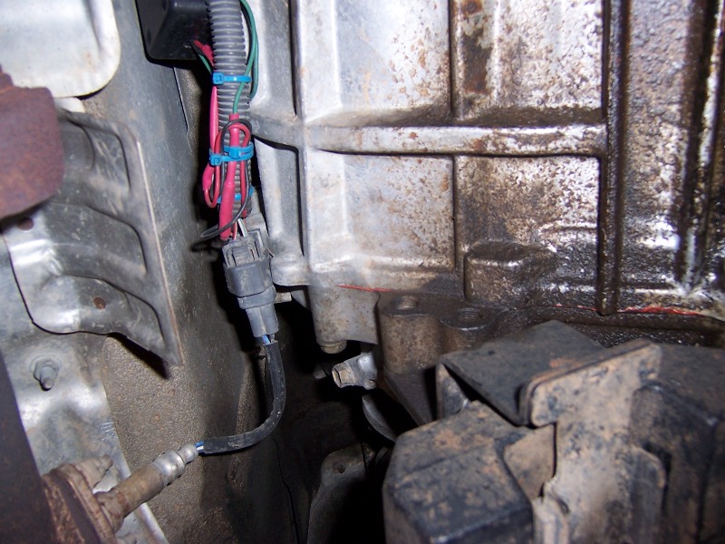
Here is how mine is installed and working great for 3+ years now.
Contributing Member
I fought this for months on my '99.
I just removed the 2nd cat, installed the URD O2 Sensor Simulator and it was good to go until I sold it.
Keep in mind, I didn't have state inspections where I lived and it was outside of Cali so there is no chance I was going to have any legal issues by changing it.
Fink
I just removed the 2nd cat, installed the URD O2 Sensor Simulator and it was good to go until I sold it.
Keep in mind, I didn't have state inspections where I lived and it was outside of Cali so there is no chance I was going to have any legal issues by changing it.
Fink
If the O2 sensor has to stay in place for this to 'massage' the signal into what it should be, then this mod makes more sense.
Since an O2 sensor is just a chemical reaction voltage generator, and assuming the ECU simply monitors this voltage, then a capacitor and resistor certainly can't replace the sine wave voltage pattern of a real O2.
The downside to this of course is if O2 goes out in the future, then a new one will be needed. At that point, a real simulator like the URD would have made more sense if was pursued from the beginning.
Quote:
Since an O2 sensor is just a chemical reaction voltage generator, and assuming the ECU simply monitors this voltage, then a capacitor and resistor certainly can't replace the sine wave voltage pattern of a real O2.
The downside to this of course is if O2 goes out in the future, then a new one will be needed. At that point, a real simulator like the URD would have made more sense if was pursued from the beginning.
The URD unit does exactly the same thing as this unit, the O2 sensor stays on the truck, it just adjusts the output voltage to make the ECU happy without a cat. Same thing only the URD version comes in a prettier box with a harness for 10x the price.Originally Posted by DailyDrive
If the O2 sensor has to stay in place for this to 'massage' the signal into what it should be, then this mod makes more sense. Since an O2 sensor is just a chemical reaction voltage generator, and assuming the ECU simply monitors this voltage, then a capacitor and resistor certainly can't replace the sine wave voltage pattern of a real O2.
The downside to this of course is if O2 goes out in the future, then a new one will be needed. At that point, a real simulator like the URD would have made more sense if was pursued from the beginning.
The O2 sensor going out at some point is possible but like i said i have not heard of anyone having long term success with completely removing the O2 sensor without a very high end box and even then they have problems and you could just go stand alone for that price.
You are also spot on on why this box can not replace the signal from a real O2 sensor.
Well, I've had the resistor/capacitor running in parallel with the real 2nd O2 sensor for a few hundred miles, and the light hasn't come on yet.
Voltage coming of the sensor is very different now, not a sine wave for sure. But no light, and that's the important part.
Voltage coming of the sensor is very different now, not a sine wave for sure.
But no light, and that's the important part.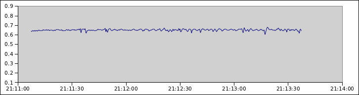
Quote:
Voltage coming of the sensor is very different now, not a sine wave for sure. But no light, and that's the important part.
Odd, mine still has the wave pattern. Could be that your OBD scan tool updates at just the right interval that it only sees the peaks.Originally Posted by DailyDrive
Well, I've had the resistor/capacitor running in parallel with the real 2nd O2 sensor for a few hundred miles, and the light hasn't come on yet.Voltage coming of the sensor is very different now, not a sine wave for sure.
But no light, and that's the important part.
Either way the light is off just like it is supposed to be!
OBDII sampled @ roughly 4 readings per second, so the graph is good. Surprising part is I remember seeing the exact spec for the sine wave in some repair manual, and my output def isn't to spec. So in theory it should throw a light, but doesn't.
Indeed, Cali spec calls for wave between 0.45v and 0.60v at the very least.