
Help wiring GM alternator in 75 Hilux
 Jan 11, 2016 | 07:27 AM
#1


Help wiring GM alternator in 75 Hilux
Looking for assistance with wiring up a GM alternator in my 75 Hilux.
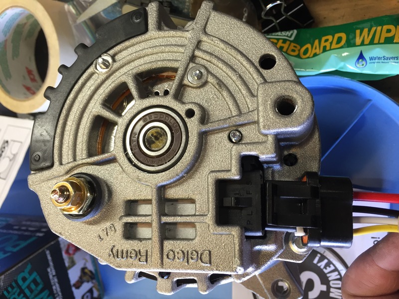
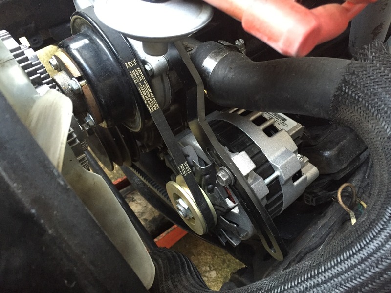
I have a Trail Gear GM alternator mounting plate and an AutoZone DL1352-1-11 alternator (100A, 180* mounting ears and v-belt, for $75).
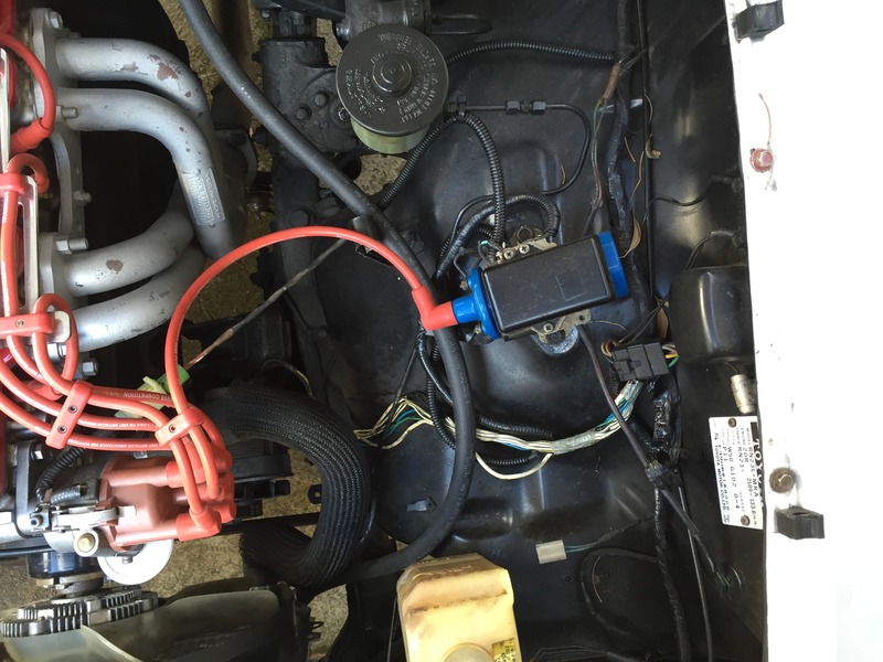
I'm most confused by the stock alternator wiring setup with the external voltage regulator. From my stock setup I have a single thick white wire coming off the output terminal on alternator. It disappears into the firewall but I assume it's the same white wire attached to my battery's positive terminal.
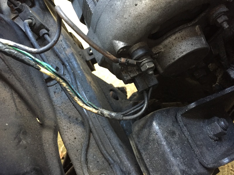
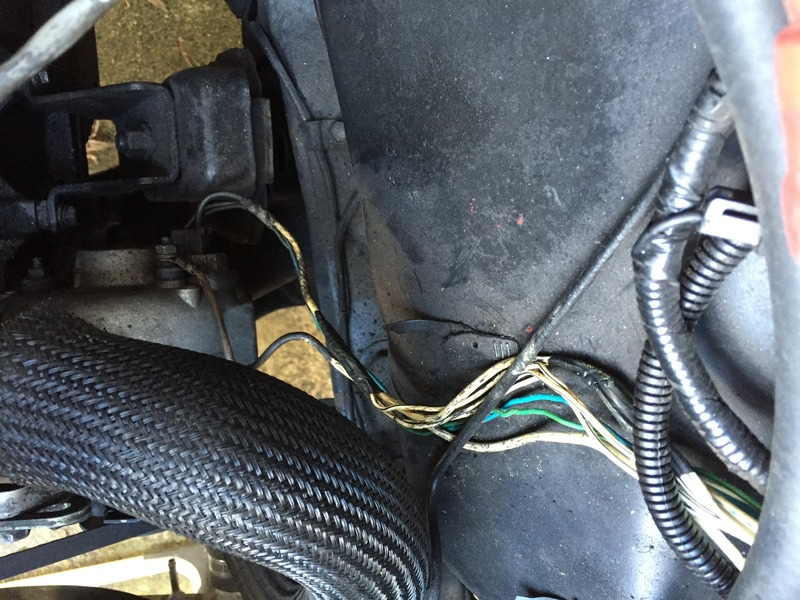
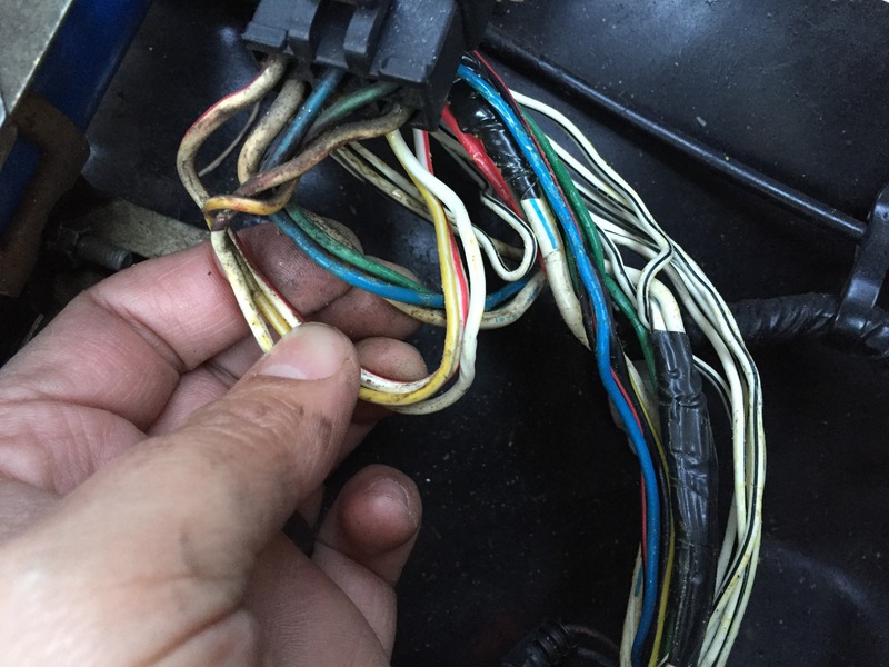
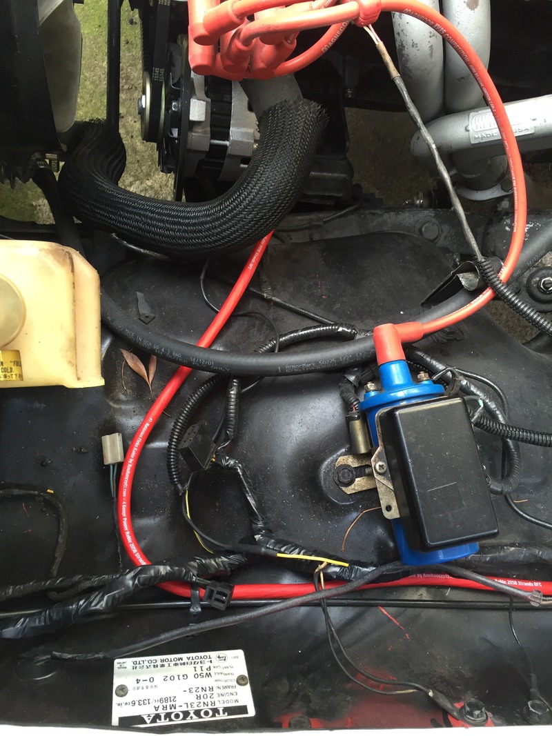
On the stock alternator plug there are 3 wires that all feed into the voltage regulator plug. One is green, one light purple, and one fatter off-white/yellowed wire that gets spliced into several times (all spliced wires feed into wiring harness going to firewall except one which becomes a ground wire on the side of voltage regulator).
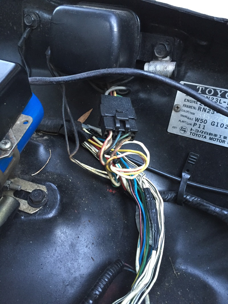
The regulator has 3 other wires connected to it, but these originate from the firewall. I'm colorblind so colors are not my forte, but I think they are a yellow wire, a white with red stripe and a white wire.
Tried reading up on these alternator swaps but just get confused by electrical. Any help is appreciated.
Here's pics of everything:
I have a Trail Gear GM alternator mounting plate and an AutoZone DL1352-1-11 alternator (100A, 180* mounting ears and v-belt, for $75).
I'm most confused by the stock alternator wiring setup with the external voltage regulator. From my stock setup I have a single thick white wire coming off the output terminal on alternator. It disappears into the firewall but I assume it's the same white wire attached to my battery's positive terminal.
On the stock alternator plug there are 3 wires that all feed into the voltage regulator plug. One is green, one light purple, and one fatter off-white/yellowed wire that gets spliced into several times (all spliced wires feed into wiring harness going to firewall except one which becomes a ground wire on the side of voltage regulator).
The regulator has 3 other wires connected to it, but these originate from the firewall. I'm colorblind so colors are not my forte, but I think they are a yellow wire, a white with red stripe and a white wire.
Tried reading up on these alternator swaps but just get confused by electrical. Any help is appreciated.
Here's pics of everything:
Jan 12, 2016 | 12:36 PM
#2
So here's what I'm thinking -
Seen other people wiring up their CS130 alternators like this:
P - unused
L - connects to 12v source/dash light
F - unused
S - connects back to output terminal on alt, then to positive terminal on battery.
Others have suggested to me that the yellow wire feeding into my voltage regulator is the wire that goes to my dash light for "charge" - so I'm going to use that wire on my "L" terminal. I'm going to run a fresh 4ga wire from the battery to my new alternator. I'll disconnect my voltage regulator and hide all the original wiring, pretty much leaving it all in place.
What ya think?
S
Feb 20, 2016 | 06:37 PM
#3
Finally got this project completed. No sparks or fire and seems to be working so I guess it's all good 
Parts used:
AutoZone DL1352-1-11 alternator, 100A
Trail Gear GM alternator bracket
KnuKonceptz Kolossus Flex Kable, 0-AWG and 4-AWG
KnuKonceptz ultimate battery terminal
KnuKonceptz KonFUSED 2-way distribution block, 100A fuse for alternator, 2nd output for future audio
Harbor Freight nylon cable clamp assortment
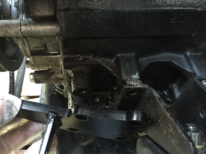
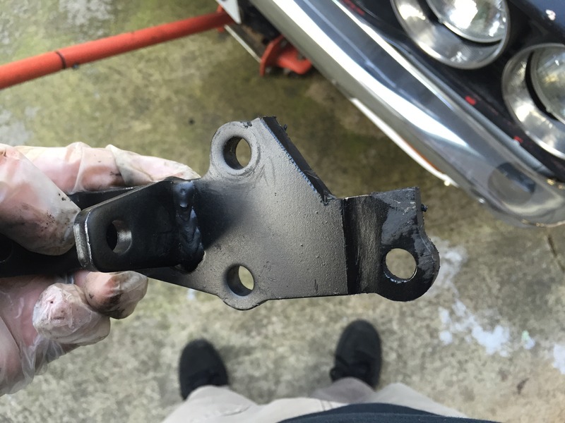
I chose to modify the TG alternator bracket by chopping out the upper right mounting hole so that it matched the 3-hole mounting pattern of the stock alternator bracket. This 4th hole interfered with a spacer welded to the stock motor mount. It's possible to remove the spacer but it was faster to modify the bracket. The part of the bracket that does insert behind the engine mount needs to be reduced in thickness to match the thickness of the spacer/stock alt bracket.
Wiring:
- I simply electrical taped and tucked away the stock wiring to the old alternator and removed the external voltage regulator.
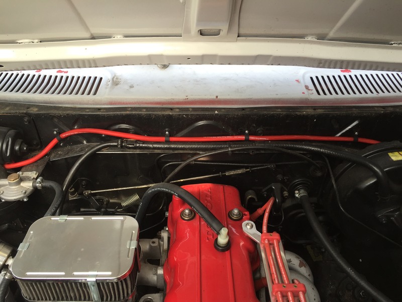
- The new alternator plug only uses the S and L terminals from the P-L-F-S plug, the other two got shrink wrapped in place for aesthetics. The S jumps to the alternator output with a ring terminal. The L wire connects to the yellow w/white tracer wire using a connector inline. This yellow wire is found entering the plug for the voltage regulator, it goes to the charge light.
- 4ga wire goes from alternator around engine bay to a 2-terminal power distribution block. I used only one output for now with a 100A fuse, since it's sized closest to the alternator max output. The other terminal will be used for a future audio build.
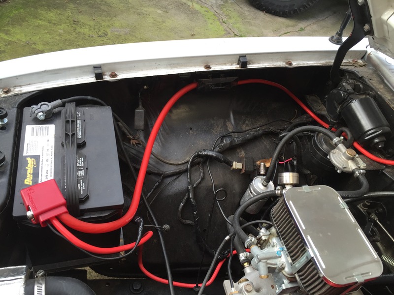
- 0ga wire feeds between the power distribution block and the new battery terminal.
- new battery terminal has multiple outputs and I connected the starter and other power wire that was on the old positive cable.
- Harbor Freight nylon cable clamps hold the wiring in place.
Pics:
Parts used:
AutoZone DL1352-1-11 alternator, 100A
Trail Gear GM alternator bracket
KnuKonceptz Kolossus Flex Kable, 0-AWG and 4-AWG
KnuKonceptz ultimate battery terminal
KnuKonceptz KonFUSED 2-way distribution block, 100A fuse for alternator, 2nd output for future audio
Harbor Freight nylon cable clamp assortment
I chose to modify the TG alternator bracket by chopping out the upper right mounting hole so that it matched the 3-hole mounting pattern of the stock alternator bracket. This 4th hole interfered with a spacer welded to the stock motor mount. It's possible to remove the spacer but it was faster to modify the bracket. The part of the bracket that does insert behind the engine mount needs to be reduced in thickness to match the thickness of the spacer/stock alt bracket.
Wiring:
- I simply electrical taped and tucked away the stock wiring to the old alternator and removed the external voltage regulator.
- The new alternator plug only uses the S and L terminals from the P-L-F-S plug, the other two got shrink wrapped in place for aesthetics. The S jumps to the alternator output with a ring terminal. The L wire connects to the yellow w/white tracer wire using a connector inline. This yellow wire is found entering the plug for the voltage regulator, it goes to the charge light.
- 4ga wire goes from alternator around engine bay to a 2-terminal power distribution block. I used only one output for now with a 100A fuse, since it's sized closest to the alternator max output. The other terminal will be used for a future audio build.
- 0ga wire feeds between the power distribution block and the new battery terminal.
- new battery terminal has multiple outputs and I connected the starter and other power wire that was on the old positive cable.
- Harbor Freight nylon cable clamps hold the wiring in place.
Pics:

Thread
Thread Starter
Forum
Replies
Last Post
WTB[MidAtl]: Stock leaf springs for a 2002 TRD
Ilovemountains
Axles - Suspensions - Tires - Wheels
0
Nov 2, 2015 07:29 AM


