When you click on links to various merchants on this site and make a purchase, this can result in this site earning a commission. Affiliate programs and affiliations include, but are not limited to, the eBay Partner Network.
I realized that the lower heat output of the gas vs. gasoline would theoretically enable one to cut out the water jacket entirely, and weld in some cooling fins instead. Pictured above is a hypothetical of such a system on a 22R block. I am not planning to undertake such a conversion, at least not with this engine, as there would be no gain in efficiency or performance, and the system would require lots of unnecessary engineering like building a cowling which covered the entire engine in order to force air from the repurposed radiator fan over it. The radiator fan would likely need to be enlarged and hooked up to an overdrive pulley system in order to push enough air over the engine as opposed to drawing it through a radiator, not to mention there would need to be tons of engineering done to the head. Though such a modification would not have any benefit, it is possible. You could consider the presence of a water cooling system to be an artifact of the engine's previous fuel system, because an engineer designing the block and head for producer gas from scratch would have most likely used air cooling.
At one time I was considering converting this 22R to run on steam instead of producer gas. Steam does have some significant advantages, and I should dig up my drawings on it sometime. The most complex part I designed for it was the distributor, which controlled electric steam inlet valves installed in the spark plug holes. All 8 valves became exhaust valves, and it needed a dry sump oil system to accommodate constant removal of water from the oil. The engine would have output something to the tune of 5 to 8 Horsepower, but over 600 lb-ft of torque at the crank with stock pistons and crank. That would have made it slow, but the nature of steam would mean that the flywheel would not be present, nor would it need a transmission, clutch, transfer case, or starter motor, and it would be able to run on a much larger variety of fuels. The power would go straight from the crankshaft to the axle. Having 4.10:1 gears in it would mean that it would be making 2,460 lb-ft of torque at the halfshafts. That's 361 lb-ft more torque at the halfshafts than a stock 22R would produce with its transmission in 1st gear, and that's straight from 0 RPM with no need to synchronize. If there was a transfer case present for a 4WD system, this rig would produce 722 more lb-ft in low gear than it would with a stock engine. Though I would have opted for a center differential in place of a T-case to convert it to AWD then I would have added lockers.
A steam rig like this could reach very high speeds but would accelerate at a pace that would bore you to death. But it would produce an incredible amount of torque to the extent that the motor could bend rods or snap its crank just from the sheer amount of force coming from the piston, in such a way that someone who was unaware of the steam conversion would assume it had gotten hydrolocked. Slow acceleration and slight risk of self-destruction aside, the real factor which dissuaded me from this motor was the 15% heat efficiency, compared to the 23-24% of internal combustion. A difference that large would certainly affect fuel costs, Imagine getting 9-10 MPG out of a stock 4Runner.
Nothing in this reply is relevant to the producer gas project, I just wanted to add a side note about some things one could do to a motor like this, but for what purpose I don't know, and also some talk about what the future could have been. I think going the way of the steam engine would have been interesting.
Last edited by Johnsoline; 05-08-2021 at 01:33 AM.
It's time for more math. Yeah math is so great so fun, that's the real reason I dropped out of high school is so I could have more time to do math.
I hate math.
I have found some lovely information from the guys over at the GEK Wiki. They've got a fair bit of information on efficiency. With this, I can get closer to what the actual fuel mileage of the truck will be.
The EPA rated the 1983 4x4 pickup gas mileage at 17MPG highway. This is the number which is important, whether or not I personally got "x" amount of miles per gallon, as this only indicates my driving habits are a little more conservative than average, and does not indicate any efficiency difference in my (then stock) 22R as compared to any other. Therefore, using the EPA rating as the gasoline MPG in this formula is the most correct number.
17mpg is 4.47 gallons per hour at cruising speed. The speed at which the vast majority of cars get best gas mileage is around 2,250RPM, in highest gear, of course. 2,250 RPM is 135,000 revolutions per hour. This works out to 324,000 liters displaced in one hour, cut in half for stoichiometric mixture that's 162,000 liters of gas needed per hour. That gives us 67.1 hp⋅h. This can also be used to calculate how big of a motor is necessary to move the vehicle at any given speed.
You may have noticed that 67HP is above my conservative maximum of 61HP at 3,000RPM that I calculated before. I don't tend to like to mix calculations because small margins of error will quickly grow by orders of magnitude, and so I will not try to go back and recalculate at this time. As the numbers sit, the truck should theoretically have a minimum top speed of 40 miles per hour. That's a bit short of my target speed of 55, but it's still at the bottom end of acceptable. I will continue to hope for faster engine speeds and higher horsepower than my conservative estimates, but I cannot say with any degree of certainty where exactly the real output will fall as the laminar flame speed information is still missing.
Update: Just found some clues as to flame speeds. I found a forum where someone has had the wherewithal to post better data. His engine has a 12:1 ratio, a 90mm stroke, and reaches a speed of at least 3,300RPM. From this I can determine that the flame speed under this compression is at least 2,475mm/sec. Calculating for the 22R's new 94mm stroke, this gives a max RPM of at least 3,150RPM.
This information makes me hopeful that I'll come out with a higher-revving motor than I hoped for. However, a bit of information is still missing, which is how to account for varying compression ratios and what percentage change in flame speed due any given increase or decrease in the ratio.
Boost brings up effective compression ratio and increases flame speeds, which will increase max RPM in producer gas fueled engines.
The guys over at Wikipedia have this lovely article on water gas. So apparently what happens here; if you were to pass steam over a hot carbon fuel a water-gas shift reaction occurs. I'm no expert at how this reaction occurs and I only have a passing knowledge of how it works, but I do know it produces hydrogen and hydrogen+engine=good. Hydrogen is a much more powerful fuel than carbon monoxide and should lend itself well to both power output and efficiency.
So I drew up this picture of a preheating system for the water. The water passes through a coiled tube on the inside of the hearth, or the outside, or through the exhaust jacket, wherever it needs to be to become steam quickly enough. Here I have it spraying into the air line through one of those porch mister nozzles, for the purpose of limiting the stream so that it doesn't spray in all at once. It's likely that I will use reclaimed water from the steam filter system for this purpose, but I worry about minerals from hard water, as well as tars and whatnot, becoming trapped in the steam line and clogging it. To mediate this issue I have considered adding a bit of vinegar into the water as it dissolves mineral deposits and will keep the lines clean, however I must concern over the possibility of a mild acid having the potential to do damage to the engine, and I have to wonder if being involved in the reaction will break it down into something caustic or corrosive. An anecdote I've said before; 'the only vape coil that never burns out is one which is made from asbestos.' It's important to look at the big picture when something seems foolproof.
Right at the end of the steam line, where it ports into the air line, are two threaded couplings on either end, one which attaches to the preheating coil and the other the mister tip, which is threaded into the air inlet. It is threaded together for the purpose of removal and cleaning. With this system the air line must pass around the outside of the core for the purpose of preheating the air before it passes into the hearth, which will subtract a nearly negligible amount of efficiency but is necessary to prevent visits from the frost fairy. Frost fairy visits occur when humidity in the air freezes onto the surface of an air inlet line which corrupts or halts the flow of air and fuel, which is commonly encountered as carburetor icing. Preventing these visits is the purpose of a standard engine's hot air intake and the carburetor's cold mixture heater, and systems for dealing with this have been engineered at least as far back as Ford's Model T. In a system like this where steam is purposely injected into the air intake line a system for dealing with frosting is particularly necessary, especially for startups in winter.
Speaking of startups in winter, another concern is what happens to these water lines when the vehicle is left powered off in wintertime and the water freezes. Water freezing in these lines is always bad, and so the solution is to use some kind of antifreeze to prevent this issue. Salt should not be used because of the corrosive effects and evaporating radiator antifreeze tends to leave behind congealed residue which will clog everything. The ideal solution in this situation is to mix the water with vodka, denatured alcohol, or some other source of unflavored alcohol with a high proof level. This will make the vehicle a bit more expensive to operate in winter and cold climates if one is unwilling to drain the entire system of water every time it is used. When the vehicle is in operation it is reasonable to use an electric heater in the water tanks, such as a block heater, especially in the condenser collection tank which is mounted onto the front of the vehicle and fully exposed to the climate, but this is not an option when the vehicle is off unless there is a nearby power source to keep the heater running.
After the water/alcohol mixture is shot through the core, any alcohol which does not immediately react will continue through until it is burned in the engine. An amount of water vapor will make it through the engine and out through the exhaust as well. As a result, no alcohol will end up in the condenser collection tank which will make it much more prone to freezing than any of the other water lines. It would be reasonable to wrap the tank in an insulating material such as wool and leather alongside having a heating element inside of it to further prevent a freeze. It is possible that in such cold temperatures the condenser will be able to cool the gas to such a temperature that the alcohol could be condensed in the collection tank, but I would not consider this effect reliable as even the presence of alcohol in the system at this stage is not guaranteed.
Side Note: I knew I would find a way to put a gasifier system on a diesel. On the Water Gas wiki, it has a paragraph called "Carburetted Water Gas." Essentially how it works is that you spray some other oil as a fine mist into a heated pot and pump the producer gas through it. By doing this, you add hydrocarbons to the gas and make a more energy dense gas. If one was to spray in an amount of vegetable oil or an algae oil, the octane rating could be low enough and the cetane high enough that it would create a gaseous diesel fuel. If you were to grow your own hemp you could press the oil out of it while it's wet and then dry the material, using the drier hemp in the gasifier and the oil that you pressed from it as the spray.
Last edited by Johnsoline; 05-14-2021 at 11:59 PM.
It seems everyone wants 40 bucks for the shorter oil pump drive spline that goes with the dual-row timing set.
Measure at 1.2"/30.5mm and cut. It's important to cut it at the right length or the chain sprocket on the crank will have axial play and resulting chain wear. The harmonic balancer holds this piece in place and this piece holds the sprocket in place. I may wind up having to add a little material back as I think I cut it a hair too far.
Now for the harmonic balancer that sat outside for 5 years:
It's an easy but time consuming workup with electrolysis, simple saltwater bath and a car battery charger. This doesn't fix pitted metal and it's important to spray off the saltwater from your finished piece or it'll just rust again. After that, it's an easy cleanup with a buffing wheel. I'll be back to the gasifier after this. I hadn't seen these things done before, so I figured I should post them even though they aren't super relevant to the topic. I've done that a lot here.
Not anything super exciting for today, but I wanted to make a post that was back on topic so here it is. On the left is what I completed today and I would have welded it in and done more if I had not run out of oxygen. On the right is a shoddy diagram of which things still need to be done. They're pretty much repeats of what I have done here, just making plate metal rings and welding them on. It would be pretty mint if I had a little bit of extra money so I could invest in a full size oxyacetylene rig so I could knock this out in a couple of days, as I have little bottles that last for only an hour.
At this stage it is important to calculate air nozzle size and hearth diameter and it would be easier to do so if I had more than just an educated guess at flame speed. This is something I'm gonna gripe about until this project is finished, because not only does it greatly affect engine performance and behavior, but it is also relevant to the design of the reactor itself. The reason is as follows; higher flame speeds result in higher max RPM, higher max RPM results in higher max volume of air the engine can pump, a higher max volume of air results in a higher demand for fuel, and a higher demand for fuel results in a larger hearth diameter to supply this fuel, and a larger hearth diameter necessitates higher-flow air jets.
From this issue, more issues arise:
1: A guess of max RPM which is too conservative will result in a hearth that is too small for the volume of gas demanded and so will artificially limit the motor's max RPM to a speed well below what it is actually capable of, which will be observable when the throttle is fully opened: the engine will accelerate, but immediately after will lose some RPM. This is because an amount of fuel will exist in the fuel line between the desegregator and the gasifier, which is immediately available to the engine. The engine will be able to draw this gas out as needed, but the gasifier will be unable to replenish it at the rate it is being used. This will cause the mixture to become lean, and the engine will slow down until it reaches equilibrium with the gasifier.
2: A guess of max RPM which is too liberal will result in a hearth that is too large for the volume of gas demanded and so it will be capable of producing gas in excess of what the engine can draw. This effect is observable when the throttle is released: the engine will decelerate, and immediately after the gasifier will begin producing smoke. This is a result of a hearth that is unable to draw air through it at a high enough speed at low engine draw, and thus is not able to get hot enough to crack the smoke at this low rate. Smoke is made of small particles of tar and maltose. The condenser-filter at the front of the vehicle is intended to filter out these contaminants in small amounts, but in larger amounts they will be overbearing on the condenser and can result in clogged tubules, sticky or seized throttle, stuck intake valves, and perhaps even stuck rings. But a definite result will be carbon buildup, stuck exhaust valves, pre-detonation, and dieseling.
3: A guess of max RPM which is too liberal will result in a hearth that is unable to draw air through it at a high enough speed at low engine draw, which will inhibit it from producing the amount of usable gases necessary for proper engine operation at this speed. This effect is observable at low RPM: the engine will run properly for a moment, and then the motor will stall. This is because an amount of fuel will exist in the fuel line between the desegregator and the gasifier, which is immediately available to the engine. The engine will be able to draw this gas out as needed, but the gasifier will be unable to replenish it at the rate it is being used. This will cause the mixture to become lean, and the engine will slow down in order to approach equilibrium with the gasifier. However, equilibrium cannot be reached as any deceleration of the motor will also reduce the necessary speed to maintain equilibrium, and so the engine and the gasifier will get trapped in a negative feedback loop as the RPM chases down the equilibrium point until the engine stalls.
I attempted to weld the inner pipe to the outer pipe and the weld did not take. I'm thinking that it may have been the rust on the inner pipe, but I've been welding with gas and the torch was unable to melt the surface of the thick inner pipe, so I'm thinking my torch is too small. I'm likely going to source a thinner walled pipe so that welding is easier to do, as I think that a higher-powered torch would just liquefy the thinner plate material. This is my first gas welding project, and as of now this is what the gasifier looks like:
Fail.
I've been taking time to think about my next move as I've been working on and acquiring other parts of the truck.
Side note: these radios actually have surprisingly good sound quality, and came in stereo models at some point. If you hooked up some nice speakers to one they would sound rather good, and actually are a bit nicer than the aftermarket ones everyone threw in during the '90s.
"Matsush-i-ta" (because the site censored their name ) made these radios for several manufacturers, and even though this is the same model that was put into the pickup, this one came out of a Jag. Anyhow, the point of the radio is to show I'll be building the truck up nice and original as I modify it, because I'd like this to be a nice and reliable vehicle and not just some beater I slapped some stuff onto.
I don't have interesting updates to post at the moment, but I haven't posted in nearly a month and I wanted to let everyone know that this project isn't dead, and also to keep this thread from getting lost in the abyss.
I've gone back and edited the first post of this thread.
Last edited by Johnsoline; 07-11-2021 at 05:25 PM.
Reason: Matsu˟˟˟˟a makes Toyota's radios
I'm back on topic with my recent influx of parts. Here's the new distributor. It looks fat compared to the old one and sticks off of the side of the motor about a quarter mile, and I'm not sure why it needs to stick off so far, but I suppose I may figure it out as I install more parts. This is the short version, the long version for the hydraulic steering models sticks off something like a foot further, and I would wonder if it was possible for it to smack against the wheel well.
This addition will add a great amount of reliability to the ignition system, but it's not necessary for the conversion. Some of my parts in storage have gotten the stolen/smashed treatment, and the distributor and pickup coil were among them. When looking at pricing for replacements, I found that this DUI distributor costs about the same as replacing the entire ignition system with stock parts, and so I went ahead and bought it. The advantage I'll have with this ignition system is of course from its much higher voltage potential, which will make ignition of this strange fuel much more reliable. All it is is a GM HEI system from an SBC, mounted onto a shank which fits into a 22R. The plastic casting of the distributor cap has four blanks where four other output terminals are supposed to be, because the cap is intended for a V-8.
On the inside of the cap is a centrifugal advance with weights that are placed loosely on and are held in place by their return springs. This is a standard and very reliable advance system. However, it is possible for the weights inside to fit under the rotor in a misaligned position, which means it is possible for them to become misaligned on their own. I would improve the reliability by holding them in position via a circlip placed onto the pivot points of each respective weight, however there is a groove on each of them and so it is entirely possible a circlip was meant to be there and I simply didn't get them on mine due to manufacturing error.
The rotor is held onto the centrifugal advance by two nylon screws, and is driven by it. If the engineering was left up to me I would have the rotor attach to the advance via a socket system, prevented from moving parallel to its axis by means of the distributor cap's axial brush, since it is in contact with the rotor anyway. Toyota's original rotor differs from mine in that it contains a steel spring which holds it in place which I would dispense with, but I think that the original attachment system is superior to this one here. I would not, however, suggest strengthening the attachment system by replacing the nylon screws with steel ones, as it is obvious the reason they are nylon is because nylon is not electrically conductive.
Underneath the centrifugal advance is the trigger system, the engine control unit, the linkages for the separate vacuum advance, and the baseplate of the distributor housing. All of these parts are of high quality and are very finely engineered. The shank of the distributor is also very well made. The pickup coil rests in the top of the distributor cap and is also of good quality. The cap attaches by spring-loaded hooks and because the whole ignition system is contained within this one cap, there are much less possible failure points within the system itself due to external wiring. The cap does not have a rubber seal but due to all parts within being sealed themselves it would be nearly impossible for water to cause ignition failure unless the distributor was fully submerged for an extended period of time. It appears to me that this device is very excellently made, but if I was to engineer it I would certainly ditch the nylon screws. The screw attachment system does appear to be also very well made and durable, but I foresee it being an eventual failure point.
Now onto my next topic, this thing:
Why does this thing exist in this fashion?
This forked thing is the only thing which keeps the ignition timing at its set point. I smoked the bolt down until I could feel that the threads were going to strip if I tightened it further and I can still grab the distributor cap and turn it by hand. The forked thing has a semicircle cut into its end where it hooks around the distributor shank, and the diameter of this cut in the fork is much larger than the diameter of the shank, and so it only retains the distributor by a small contact point which does not have enough friction to hold it in place. This retaining system is just, ... it sucks. I understand that the reason it is like this is because they wanted the ignition timing to be infinitely variable, and they couldn't make the retainer go all the way around the shaft because the shaft is a solidly milled piece which is larger at each end of the shaft than along the middle, so that a solid retainer which goes all the way around cannot possibly be put onto it. Toyota's original system is a good system for retainment, but has issues of its own because the bolt-in-groove system they use does not have a groove which is long enough to account for wear, which means that over time the ability to adjust it to a fine degree is lost. Everyone who has tuned these engines for a long enough time knows the issue with not being able to time the spark to the degree they want it, and so removing the distributor to advance or retard the drive gear by one tooth, only to find that they've gone too far, and having to go back and just accept that they can't adjust the timing to exactly where they want it because they can't turn the cap quite far enough. This is the problem with Toyota's original system; it works perfectly fine when new but as the teeth on the distributor gears wear by thousandths of an inch the distributor cap has to be turned just slightly further each time until it becomes impossible to adjust it far enough. If the track which the retaining bolt sits in was just a quarter of an inch longer this would not be a problem, but it is obvious that this issue is the one that DUI is trying to solve with this fork retainer thing. However it is obvious that the person who made this retainer only thought about how it would work and not how it would fail, and my solution to this problem will be to ditch the fork thing and replace it with a retainer which bolts onto the distributor shank in the same fashion that a connecting rod attaches to a crank pin, because that will be the superior way to give infinite adjustment but apply enough friction that the distributor cannot be bumped out of time or slowly rotate on its own.
Last edited by Johnsoline; 08-03-2021 at 09:51 AM.
Since this thread has become a mix of a regular build thread and whatever you would call a gasifier project thread, I'm gonna occasionally include other odds and ends of note.
I find it frustrating that it is slowly becoming harder to track down rebuild/repair kits and parts for equipment. I have no doubt this is intentional, to encourage you to buy an entirely new and expensive item instead of just being able to replace a single broken piece of an otherwise good part. This is a problem I had with my brake master cylinder, the reservoir rotted to pieces in the sun as you can see in some of my previous pictures of the engine bay, but the actual brake master is perfectly fine. I can't hunt down the 10� plastic cup anywhere and I'm expected to drop a Benji on replacing the entire master cylinder to get one. This is absurd, and in the interests of my own funds and in my pursuit of sustainability I'm not going to put up with it.
This is my new master cylinder reservoir. I think the rat rodders would approve. Also, brake fluid instantly dissolves shellac and eats paper gaskets, so I had to silver-solder the fitting.
In the goal of preserving resources, saving money, and maintaining a good quality of life, I urge everyone to be innovative and to support businesses that sell repair kits and replacement parts for all the tools and equipment that they produce. It's good for the world, and it's good for the wallet. There is no good reason to have to be wasteful both of items and of money because you can't find one cheap piece to fix an otherwise perfectly fine thing.
Sorry that I've been slow on updates recently, and that I haven't been posting much about the producer gas rig as of late, it's because I'm replacing the electrical system and putting up the transmission and stuff, the whole wiring system rotted away over the years. I've been spending this time getting the truck "drop-ready," if you will, i.e., so that I don't get other engine problems when I drop the rig into it.
Last edited by Johnsoline; 08-27-2021 at 04:58 AM.
For the main filter unit I will be using a condenser built out of a radiator that I found in a 4runner at the junkyard, and being one of the desert editions, (this one in particular being from Nevada) it had an original radiator in it that was oversized from the standard, being nearly double the size. This will be perfect for my system. Momentarily I considered using this bigger one as my radiator, but because of the lower energy density of the gas the engine will never get hot enough to make use of its advantages, and so it will be the condenser.
The device will have to be modified to work well as a condenser. All parts on a brass radiator are soldered together, and all you need is a blowtorch and a common screwdriver. Be careful when prying, as the screwdriver can act as a can opener and split your solder trough.
I have to modify this because it will be mounted in front of the radiator, and so as the inlet/outlet piping is facing in the same direction as they are on the radiator I won't have room to connect plumbing. If I turn the condenser around, the plumbing will stick out awkwardly from the front of the truck and the gas will have to make several sharp 180� turns. The radiator hose that I'll be using at this point also doesn't like to make sharp turns without kinking, and even though I could remedy that by making fittings, the problem of increased drag on the fuel system will still exist. Even though the gas will be pumped in, the engine will still have to do some of the work and any sort of resistance will decrease its power output and efficiency.
I'm taking out the upper connection point and reattaching it directly on top of the condenser at an angle. I would have rather attached it to the side of the unit but that would have been in the way of the mounting bracket and that would have gotten very complicated, and also would have demanded that I go and buy some brass plumbing. I had to do over the old hole with a piece of sheet steel silver soldered on.
After removal of the bottom end I removed the automatic transmission intercooler, the petcock, and the hose fitting. Even though this takes a nut, it's still sealed with solder and so has to be heated.
Here's an ATF intercooler. It's just a pipe inside of another pipe and the fluid moves between them. This is a secret piece that will help me later.
Now is a good time to clean out all the crud in the tubules. This crud is what causes radiators to clog. It forms from broken down radiator fluid which is why radiator fluid must be changed every few years or so. It's a compound containing byproducts of ethylene glycol so you might consider it a caramel of sorts. Though I did also find some permatex gasket pieces in them, and there was no evidence of a permatex attempt to fix any radiator problem ... hmm ...
All holes in the bottom I've blocked with sheet metal plates silver soldered in place.
Here's the condenser unit completed. You may notice that there is no output plumbing on this as all ports have been blocked off. That's because a cylinder will be attached right below, to function as the collection tank for the tar and condensate, which will be attached to two pipes which fall vertically from the bottom of the condenser.
Last edited by Johnsoline; 10-17-2021 at 06:01 PM.
So during soldering of the condenser some of the solder tray split, and that made it leak like a sieve.
Psh.
My solution here is to remove the broken trough and solder on a piece of copper sheet bent into its shape. For the purposes of cruelty the copper sheet I got was 3 thinner sheets fused together with some kind of polymer to serve the purpose of making the life of anyone who actually tries to use the sheet into a nightmare. That took what was going to be a neat solder job and turned it into a janky mess, but nonetheless I got it to seal.
When I was testing that it held pressure I remembered that it would actually be holding a slight vacuum. And so I sucked through the tube and realized that the supplied radiator cap relieved vacuum, as intended, as it's supposed to allow fluid from the overflow reservoir to be drawn back into the radiator it protects. I liked how it could release pressure if the engine were to backfire into the condenser due to an air leak, but I needed one that did not relieve vacuum. I thought perhaps I should disassemble the cap and would have to figure out how to engineer a spring loaded mechanism for it so that the condenser would not be able to suck in air through the lid but the lid would blow out if pressure inside was present.
Cork.
Last edited by Johnsoline; 11-05-2021 at 06:33 PM.
I need to add a couple of extra controls to the truck as I need a temporary switch for priming the motor with fuel via an electric blower. The dashboard does not have adequate real estate for mounting controls so I've had to get creative. I'm going to be using the starting position on the key switch for running the primer, as doing so will require the good manual dexterity in the hands.
Here I've mounted a foot-operated switch on the driver's side kick panel. It looks and feels the same as a floor-mounted dip switch, but it does not latch in place to set high beams on or off, and it's built to handle the current of the starter motor, though I will not be running that much current through it as it will simply control the relay.
Now on with some complaint:
I had some trouble when I finished with the starter not working after my modification. Under the impression that I had misunderstood how the circuit works, I went along with taking it apart. The gearbox was held on with Phillips screws that were smoked down to the point of being unremovable as Phillips screws will strip under torque. I could not have said whether they were smoked down by poor workmanship or purposely to prevent repair, but they came pre-stripped. With an electric drill and an undying hatred for Phillips screws, I went ahead and annihilated them. I assumed this would be the worst part, but it was only a sign of what was to come.
All of the pieces in the gearbox had virtually no grease on them. Skimping on grease leads to gear deterioration and destruction of temper from friction. The issue is double as destruction of temper makes the gears soft which accelerates their wear even after grease is added.
But this is the icing on top. Inside of the motor housing was this random loose screw that doesn't even go anywhere on the starter! It's sloppy workmanship at its finest!
Now if I was a bit more nihilistic I would be accusing the manufacturer of sabotage, but I think it's an example of workers at the Mexican refurbishment plant not being paid enough to care about quality, nor really being educated about how this device even works. This is a problem with many foreign-built parts, what with the workers not knowing how the thing works and often not even knowing what it is. US-built equipment generally tends to be made by workers who know what they're doing and who are paid an hourly wage, while many of the nations that we import from are operated by workers who are told "put this thing in that thing and send it" and on top of it all are paid per unit and so are too busy trying to put out high numbers to care at all about the quality of their work. Well-paid workers with hourly wages have the time to care about quality, and stay employed at their job long enough to be good at it.
Addendum:
Here's the finished starter, essentially rebuilt right after production, and before its first use, just to get it working, and I had modified to have a positively-grounded relay coil. In this type of application I believe that common screws are superior to Phillips screws as not only are the screws often smoked down, but common screws as well as Roberts screws and the like don't strip out or jump when you put an amount of torque on them often necessary to remove screws that have been exposed to mud, sand, water, and road salt; which are all exposures that starter motor screws can be reasonably expected to suffer. On the other end I have put square nuts because they sit so closely to the housing that they cannot rotate and therefore need no wrench, which simplifies assembly.
Last edited by Johnsoline; 02-06-2022 at 10:49 PM.
So a problem I'll be having is my need to keep the truck running when I'm not willing to spend the 20 minutes to go through the startup procedure after a five minute stop. I fear that someone may try to drive the truck away when they find it running and unattended. Though they wouldn't manage to get but a few miles, walking out to find a vehicle missing would be very frustrating. And so to prevent that, I have engineered a lockout computer.
This is a lockout computer built with relays. The mark "NO" means "naturally open" and "NC" "naturally closed." It uses if/then statements to function and has several self-latching relays to perform basic memory function.
The system is set by pushing the arm button, which also activates a light to indicate when the system is armed. This activates the first self-latching relay so that even when the button is released the system will remain activated. This relay activates one other relay, which connects the button on the clutch pedal. If the clutch is pressed down to shift into gear, a second self-latching relay is activated, which disconnects the starter button and cuts power to the distributor, and also sounds an alarm bell. Because the first and second relays are latched, releasing the clutch pedal will not turn off the alarm, and the engine cannot run and cannot be turned over. The truck is now locked out and cannot be jump started nor hotwired.
On the bottom right is the second computer, and I've drawn this schematic as an example of how the system can be disarmed and the vehicle unlocked.
In this example, the first thing to be done is to pull the parking brake. This will connect a relay to ground. The second step would be to push in the cigarette lighter, which will activate a relay, and will also disconnect a second relay from its line. The relay from the cigarette lighter will activate the relay which is connected to the handbrake switch, which is self latching. Once that relay is on, the cigarette lighter is pulled out, which disconnects it from the self-latching relay and reconnects it to the relay which it was previously disconnected from. After this step, the horn is sounded. Sounding the horn will activate the relay which supplies positive voltage to the first self-latching relay of the first computer, which will disconnect positive voltage, allowing the relay to unlatch and causing the lockout process to collapse. The alarm stops, and the vehicle can now be turned over and started.
The system allows the operator to have a "code" to unlock the vehicle by manipulating some of its regular controls in a certain order. If the controls are not manipulated in order, the computer will not unlock the vehicle.
The outcome is that, to leave the vehicle running, the operator would simply push an arm button, and he could see that the system is armed via its indicator lamp. If the clutch were depressed to shift into gear, the vehicle would lock out, shut down, and could not be restarted. In this design, to unlock the system and drive the vehicle, the operator would pull out the brake, push the cigarette lighter in and then pull it back out, and then sound the horn.
The way one would design this system could be any way - it could involve a pattern involving the windshield wipers, the radio, the hazards, or any other combination of controls in the vehicle. Connected in a fashion like in the schematic, all of these devices retain their ability to function normally as well.
The schematic is labeled "1101." That is because this unlocking process is a binary code, and presented as numbers, the code is 1101.
You may notice that on the cigarette lighter the negative line splits into two, one which goes to the relay coil, and one which passes through a resistor before going directly to ground. The reason for this is because a cigarette lighter uses a lot of amps and the current could burn up the coil of the relay, and so it is also connected directly to ground through a resistor, the resistor causing only a portion of the current from the cigarette lighter to pass through the coil. Say if the cigarette lighter used 15 Amps and the relay only used 1. The resistor value would be calculated to allow only 14 Amps through, so that only 1 Amp of the 15 would pass through the relay coil.
The system can also be installed in a vehicle which has an automatic transmission, with the only change being that the lockout is caused by the activation of the reverse lights instead of clutch depression, so that shifting out of park causes the lockout.
Last edited by Johnsoline; 11-09-2021 at 02:25 PM.
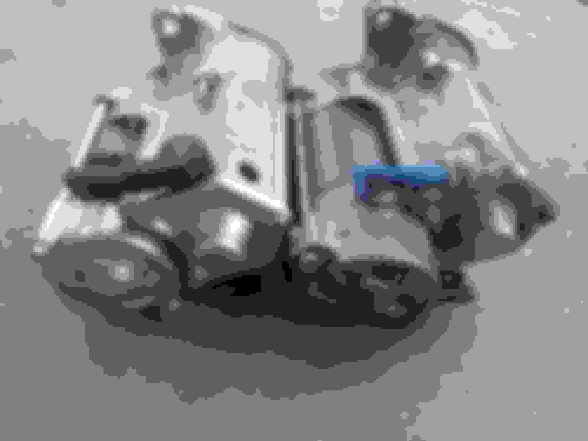
I was digging around today and found my old broken starter motor. I decided to compare it to the new one that I just got working, and I found some pretty stark differences:
Right away you can see the difference between the commutator housings. The one on the right is made of pressed sheet metal with retaining screw sockets spot-welded onto it. The one on the left uses a single-piece cast housing and is the original starter motor. The commutator inside is held in place by those two Phillips screws, and they work well for this purpose as the commutator body inside the housing which they screw into is made of sheet metal; they prevent over-torquing and stripping of the threads, unlike the new one on the left which came with the commutator screws pre-stripped.
The cable from the relay to the motor on the new starter is already deteriorating. Unlike the cable on the original starter which does not show any signs of deterioration.
Disassembly of both starters to take a look inside.
The large gear on the output shaft is a ratcheting gear, so that the starter can turn the flywheel, but if the flywheel is already turning then the gear will freely spin on the shaft. This prevents the teeth on the flywheel and the output gear of the starter from getting chewed up if the starter is activated while the engine is running. The ratcheting mechanism in this gear is broken in the disengaged position, and so the starter motor would spin up but could not crank the engine. This is the reason the original starter came off.
The original starter comes with combination screws, so you can use the leverage of a common screwdriver if they become stuck. If these were Phillips-only screws I would have had to drill them out as well.
The new starter motor housing does not fully seal, which will allow dust and water to enter the gearbox and contaminate the grease. The original housing does not have any leaks here. At this point, I decided to use the new starter for parts to fix the old one.
I forgot to snap a picture of the geartrain. The new starter motor has a drive gear milled into its shaft, and the old one has a splined shaft which slides into a drive gear. This is so the drive gear can be replaced if shredded, as opposed to the mentality present in the new starter which is one of entire starter motor replacement.
The old starter motor is now restored and functional, at the expense of the objectively inferior replacement. These are not the same starter unit; the original starter has lasted 350,000 miles for a reason, and that reason is care and patience put into both design and assembly with the expectation of it having to go through its duty cycle in sub-optimal and often sub-aqueous conditions. Auto parts store replacements are made with the presumption that they will be put into slowly dying vehicles that only need to be kept running as short-distance road drivers until they are replaced, so corners are cut and therefore these parts are substandard for a vehicle which is desired to have a long and reliable life.
The vast majority of starters quit because their brushes wear down and it's not a complicated endeavor to replace them. This original one has had them replaced many times before the ratcheting gear gave out and the ones which are still in it are almost like-new. From what I can see externally it appears that the ratcheting gear is supposed to be pressed onto a bald shaft and it has become loose over time because of tens of thousands of heat cycles, but I will find out when I disassemble it.
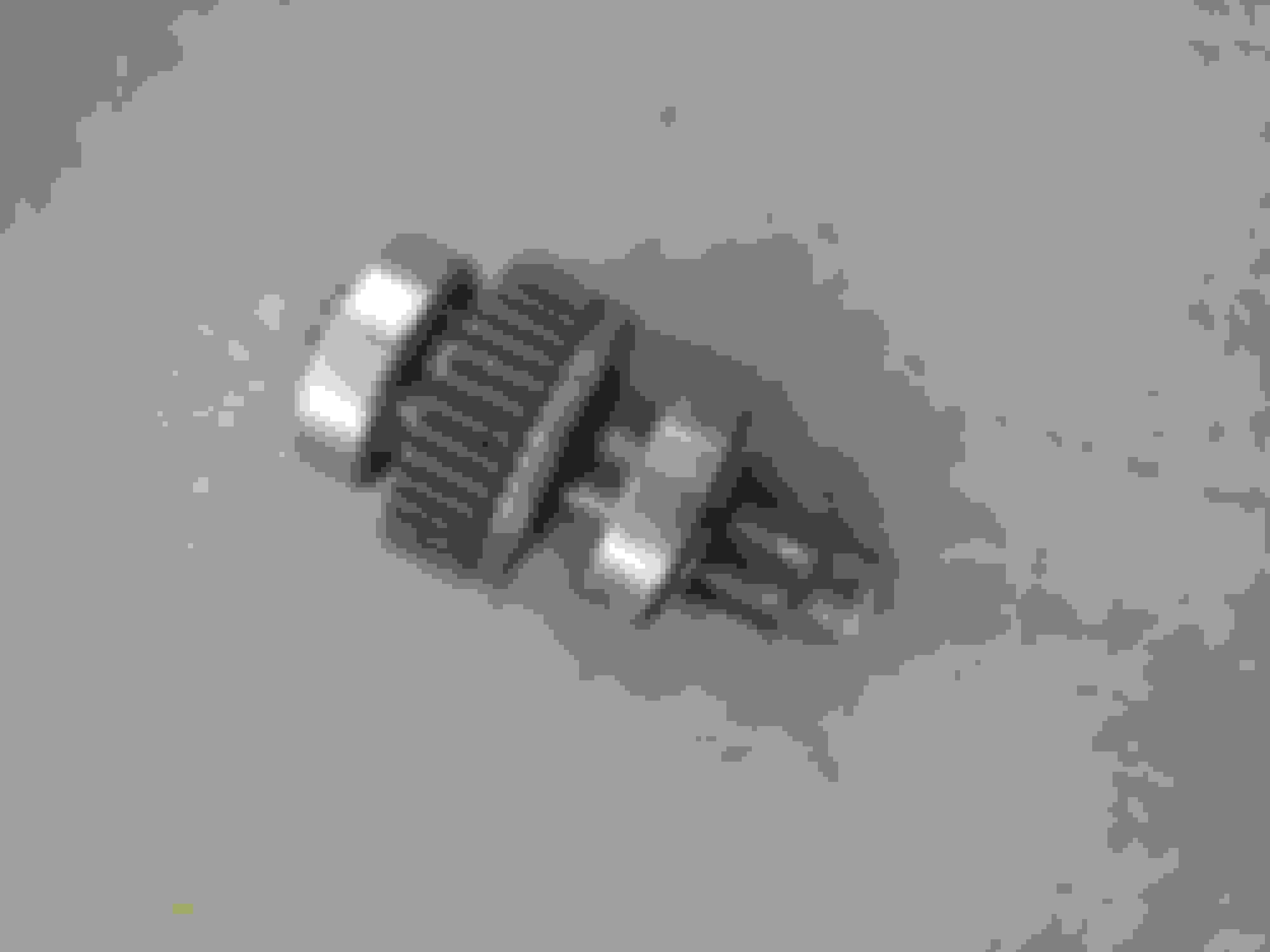
Addendum:
Pictured is the one-way clutch, which I previously called a "ratcheting gear." Within it are 5 roller bearings, one of them pictured top right, which ride in grooves which are tapered. Pictured top left you can see that they are held in place by springs. In bottom left you can see that the grooves have a stair-step milled into them. The pinion shaft has friction against these rollers and when it is turned in the proper direction the rollers are forced up onto the steps and are wedged between the inside of the gear and the pinion shaft, increasing friction to such an amount that force can be transmitted between the gear and shaft. Bottom right you can see the pinion shaft has worn to an extent that there is a gap between it and the bore of the clutch, which is far enough out of tolerance that the rollers have no friction against the shaft and therefore the clutch cannot operate.
In this current state I believe that it can be overhauled into workable condition at least once, by replacing the five rollers with some of a slightly larger diameter. That way the pinion shaft will resume having the necessary amount of friction and the lack of proper tolerance can be compensated for.
Last edited by Johnsoline; 02-06-2022 at 10:52 PM.
I've gone back and edited my two posts on the starter motor. The reason is because I've learned some important information about it, as follows:
I had decided to convert my starter solenoid to run on negative, in order to avoid adding a relay, so that my electrical system would be less complicated. But after spending many hours drilling out the coil, modifying said coil, switching polarities and a whole load of other nonsense, I put the starter motor into the truck to find it didn't work. So I took it back out and did some experimentation to try to find out the malfunction. What I found out was that the coil worked, but was not strong enough to draw in the plunger. This didn't make sense to me, so I started from square one to figure out what I missed, and what I missed was rather important.
This is my diagram of the starter motor solenoid coils. I figured the second grounded line coming out of the coil was some sort of shunting system, but when I spent more than zero seconds thinking about it, this didn't make sense. What's actually going on here is that there are two coils in this coil package.
So what's going on here, is that there is one coil, marked "draw coil," that draws the plunger in; pushing the pinion out of the starter to engage the flywheel teeth, and at the end of its travel, bridging the gap between the two copper contacts in order to send power to the starter motor. This draw coil is grounded to the positive terminal of the starter motor, because that terminal is connected to ground through the starter motor windings while the contacts are not bridged. But once these contacts are bridged, the motor is activated and therefore the negative side of the draw coil is now connected to positive instead of ground, and so the coil stops working as both ends are connected to positive, so there is no voltage difference. The speed at which this happens is important, because the draw coil cannot handle this amount of current without toasting itself, but because it's only on for a split second it doesn't have enough time to get hot enough to burn.
Then, there is a second coil which serves to hold the plunger in the 'activated' position, and this "hold coil" is grounded to the chassis of the starter motor, so that it does not deactivate once the plunger is down, but instead stays active until the starter button is released. This coil is much weaker than the draw coil, as it takes much less energy to hold the plunger in place than it does to draw it in.
The simplicity of this mechanism is ingenious, but its nature also means I cannot so easily swap it to negative as I thought. And so I restored it to its original design. However, having to add a relay to the design isn't so bad after all, as I have found that it doesn't actually make my electrical system more complicated after all, as I found that I can remove one relay from my lockout computer because of it.
Last edited by Johnsoline; 02-06-2022 at 11:48 PM.
I had to look up what "producer gas" was and then it dawned on me where I'd seen this before. I'm a VW guy at heart and the Germans did this to all sorts of war VWs toward the end of the war as their fuel supplies became less and less reliable. Here are some photos and info just in case you'd not seen them before.https://blog.heritagepartscentre.com...re-6small1.jpg https://blog.heritagepartscentre.com...d-burning-vws/ Cool project for the Toyota. Best of luck with it.
I had to look up what "producer gas" was and then it dawned on me where I'd seen this before. I'm a VW guy at heart and the Germans did this to all sorts of war VWs toward the end of the war
The people who did it the most were actually the Swedish, by a long-shot. That's why the UN document I linked about producer gas was written by the Swedish, because of how much experience they had with it.
There were many things done around the world; the French had a practice of stacking several head gaskets on top of one another to lower an engine's compression enough so that more available kerosene could be used, and in situations where it couldn't be found, substituted it with producer gas. The Australians opted to strap comical giant rubber bags onto the tops of their buses to fill with coal gas, which is also produced in a gasifier. The Germans strapped gasifier machines onto civilian cars, but also figured out how to use the same device paired with a Fischer-Tropsch reactor to convert wood or coal into gasoline for use in military vehicles.
One of the last (and to my knowledge, never built) designs that the Germans came up with was a unit that was modified to have a jacket around it, so that hot exhaust could flow around the hopper and help to heat it, increasing efficiency. This idea is one that I've incorporated into my designs, albeit with a catalytic converter present in the jacket, as the catalyst will make it even hotter.
The water gas system, properly called the "water gas-shift reaction," has its origin in the gas lighting and heating industry during the 19th century. At first, producer gas was made with coal in a gasifier in order to fuel gas lights and heaters, but along the way it was discovered that passing steam over the coal bed produced a more powerful gas, which in the modern day we call "water gas" but at the time was called "hydrocarbonate." It was found that the oxygen atoms from a water molecule would bind with the carbon monoxide, converting it to the much less dangerous and inert carbon dioxide, but leaving the more powerful and safer hydrogen behind. This made for brighter gas lamps, hotter heaters, lower costs, and greater efficiency, and remained the system until the invention of electric lights and discovery of gas wells.
On a side note, up to the point that gas wells were discovered, all fuel gases were artificially synthesized in a gasifier. This is what coined the term "natural gas."
Last edited by Johnsoline; 02-24-2022 at 08:17 PM.
My '87 lost compression, and so I've been holding off on this project for a while to deal with that, as it's my only vehicle at this time. As of now I'm starting to get back into this project but it's going a bit slower due to the financial issues we're all contending with.
As of right now what really needs to be done on the producer gas truck is to rebuild the entire wiring harness. I'll try to spare you the nuisance of having to scroll past that but I will post about it anyway if I come up with or discover a better way of doing it than Nippondenso. Which will likely happen, considering these trucks and their famous electrical issues.
I've determined that the desegregator I've built will not be adequate for my needs. The design I made is a good one, I believe, but there are a few things about it that are undesirable, notably that the size and shape of the face of what was the float bowl is not easily modified to include a gas inlet port of the appropriate size and shape. After doing more detail work I decided that the gas inlet port should be larger than the air inlet ports, even though the air/fuel ratio should be 50/50, so that the increased constriction of flow on the gas side can be compensated for without so much need for restricting airflow with valves and baffles. A more appropriately dimensioned desegregator will be less constrictive and will allow for more power and efficiency, as well as will be more reliable. I will be leaving up the images and text surrounding the building of the first prototype for the purposes of documentation. As of now I am collecting small items of zinc and pot metal for the purpose of casting a new body which is designed for my purposes, as it is an acceptably strong metal and casts easily at low temperatures. This new purpose-built desegregator will incorporate all of the modifications I did to the 20R carburetor while I was converting it into the first prototype.
Last edited by Johnsoline; 07-16-2022 at 04:48 AM.

 04-29-2021, 08:38 PM


 ) made these radios for several manufacturers, and even though this is the same model that was put into the pickup, this one came out of a Jag. Anyhow, the point of the radio is to show I'll be building the truck up nice and original as I modify it, because I'd like this to be a nice and reliable vehicle and not just some beater I slapped some stuff onto.