
98 4Runner moonroof safety switch Defect and One Touch Operation moD
 Aug 10, 2010 | 06:44 PM
#22
Registered User
Joined: Sep 2006
Posts: 190
Likes: 1
From: Boston, MA area
Does this help?
http://www.ncttora.com/fsm/1996/SIL/.../srsy/insp.pdf
http://www.ncttora.com/fsm/1996/SIL/.../srsy/insp.pdf
Aug 10, 2010 | 07:03 PM
#23
Thread Starter
Registered User
Joined: Jul 2009
Posts: 21
Likes: 0
From: Boulder, CO
Skid - Thanks for the .pdf!!
That is for a 2002 it looks like and from what I've seen they changed the way the moonroof switches are set up but let me compare it to what I've got and I'll let you know.
That is for a 2002 it looks like and from what I've seen they changed the way the moonroof switches are set up but let me compare it to what I've got and I'll let you know.
Last edited by Jefe23; Aug 10, 2010 at 07:04 PM.
 Aug 18, 2010 | 11:17 AM
#26
Thread Starter
Registered User
Joined: Jul 2009
Posts: 21
Likes: 0
From: Boulder, CO
One-Touch moonroof setup on my '98 4Runner
After creating this thread about defeating the halfway safety switch on my moonroof https://www.yotatech.com/forums/f2/i...runner-216675/ I decided to create a one-touch open and close for my moonroof. It was fairly inexpensive ($35) and only takes about 30 minutes to complete depending on skill level.
***** This is for information purposes only, because this relates to defeating a safety switch and adding aftermarket components, use information at your own risk. I cannot be held liable for damages. Always test wires before attaching any electrical components as vehicle wiring changes from year to year.*****
Here's a preview of what it should look like finished: http://www.youtube.com/watch?v=_TQuhRiwOHU
Parts used:
- (2) DEI 528t - These are variable pulse timer relays
- (1) 30A SPDT relay
- Solder/tape
Here's a picture of one of the 528t pulse timer relay: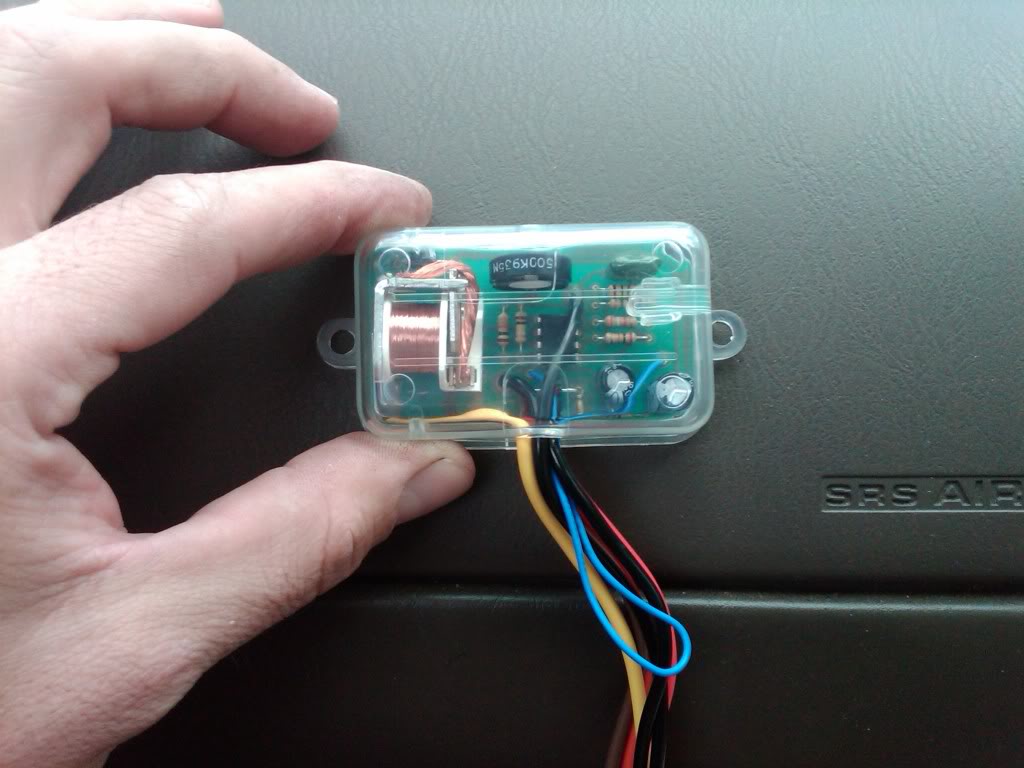
Next was the install. Again, these were the wire colors in my 1998 4Runner but your wire colors may be different. Always test before attaching any wires.
Once you take town the console that holds the switches, you will look for the harness that comes off the open/close switch. You will be using (3) wires from this harness: black (- GND), lt green (- Close), and red (- open). You will also need to remove the factory control module which is held in the roof by (1) 10mm bolt which is located just to the passenger side of the center console in the headliner.
Next, you need to locate three wires that will be used from the control module: white/red (+12v IGN), red (+12v position sensor), and red/blue (+12v second position sensor). Here's a picture for reference: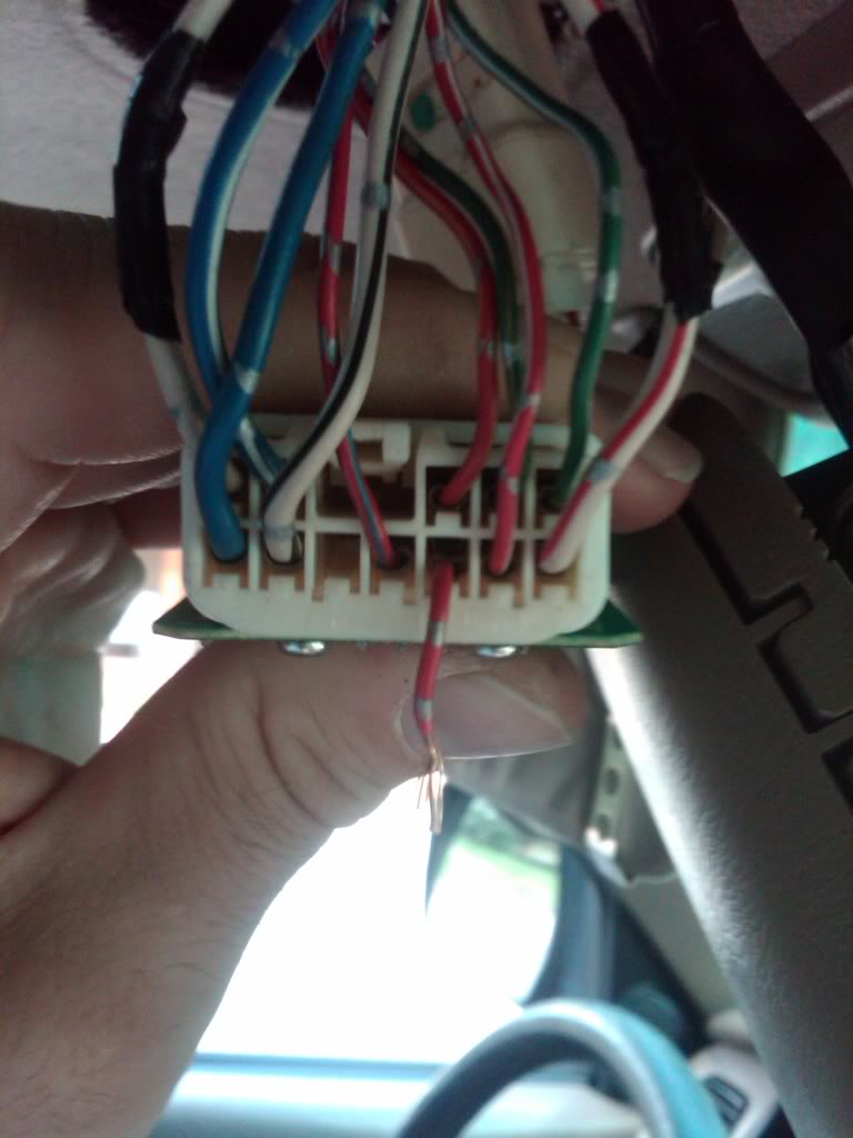
Here's a picture of the first 'test' before everything was cleaned up: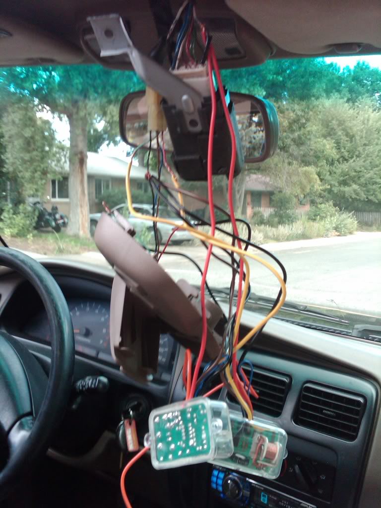
Aug 18, 2010 | 11:27 AM
#27
Thread Starter
Registered User
Joined: Jul 2009
Posts: 21
Likes: 0
From: Boulder, CO
Once all wires are located, you will start to connect the pulse timers and SPDT relay to the factory module.
****Note: this setup is basically mimicking the press of the moonroof switch while utilizing the factory limit switches as to not burn out the moonroof motor.
Pulse timer wiring:
You will have one for open and one for close.
- OPEN:
- Red(+12v) - connect this to the larger gauge WHITE/RED (+12v) wire in the factory module harness.
- Brown (Pin 87) AND Black (- GND) - connect these to the BLACK (- GND) wire on the switch harness or use any good chassis ground.
- Black/white (- Trigger input) - will attach to the switch side of the RED (-) wire coming from the switch once it is cut.
- Yellow (- Pin 30) - this will attach to the module side of the cut RED (-) wire in the switch harness.
- CLOSE:
- Red(+12v) - connect this to the larger gauge WHITE/RED (+12v) wire in the factory module harness.
- Brown (Pin 87) AND Black (- GND) - connect these to the BLACK (- GND) wire on the switch harness or use any good chassis ground.
- Black/white (- Trigger input) - will attach to the switch side of the LT GREEN (-) wire coming from the switch once it is cut.
- Yellow (- Pin 30) - this will attach to the module side of the cut LT GREEN (-) wire in the switch harness.
SPDT relay wiring:
- Red (+12v) AND Brown (Pin 87) - connect these to the WHITE/RED (+12v) wire in the factory module harness.
- Black (- GND) - connect this to chassis ground.
- Yellow (Pin 30) - Connect this to the RED/BLUE (+12v) wire in the factory module harness.
*** You will also need to cut the RED wire on the factory module (as seen in the harness picture) and tape off each end.
The reason for adding the SPDT relay is to 'reset' the limit switches to the correct position and there is now no need to press any buttons twice.
Once all of the wires are hooked up, you will need to set the pulse timers to the duration of your moonroof travel. There is an adjustment on each timer that is selectable from 1-90 seconds. Here is a picture of where I set mine: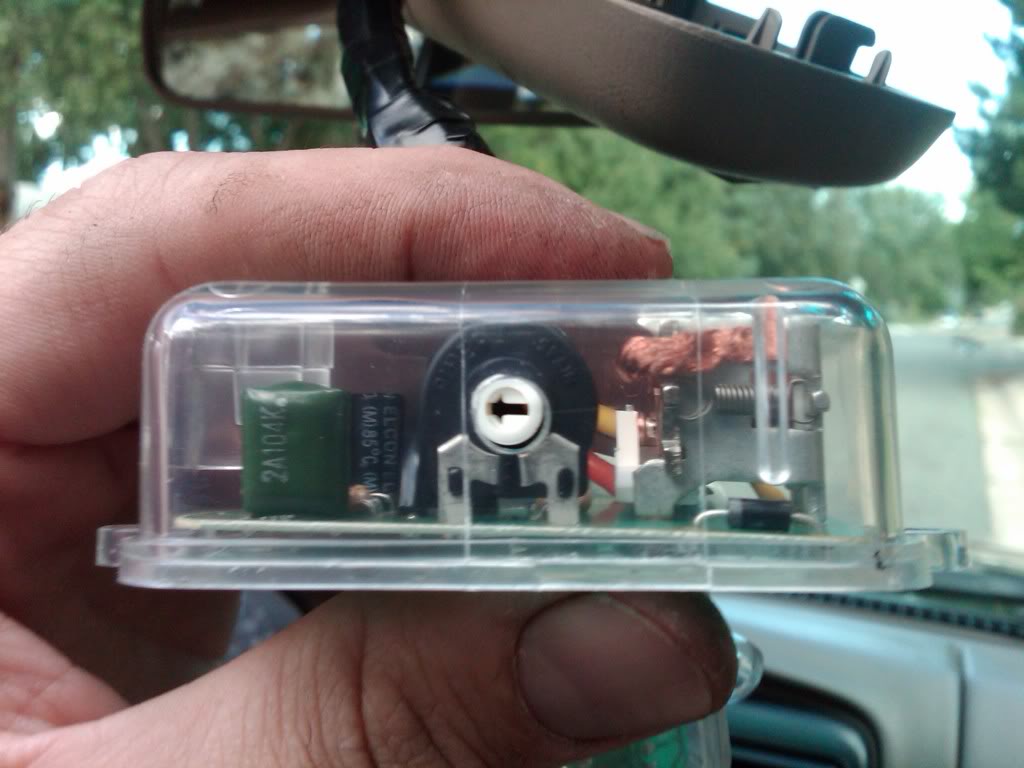
Couple more notes:
Granted, this is my first attempt at this and it's not a perfect system but I will continue to improve it. The only 'issue' I can see at this time is that you cannot stop the travel with the switch, either open or close, in the middle of the roof. It is either open all the way or close all the way. The limit switches WILL activate if there is something stopping the travel, just so you know.
Please let me know if you have any questions and ENJOY!!
Last edited by Jefe23; Aug 18, 2010 at 11:42 AM.
Aug 18, 2010 | 11:45 AM
#28
Thread Starter
Registered User
Joined: Jul 2009
Posts: 21
Likes: 0
From: Boulder, CO
One-touch thread
Here's a link to my one-touch thread! Let me know what you think!
https://www.yotatech.com/forums/f2/o...runner-218399/
https://www.yotatech.com/forums/f2/o...runner-218399/
Aug 23, 2010 | 07:37 AM
#31
Registered User
Joined: Sep 2006
Posts: 190
Likes: 1
From: Boston, MA area
Looks good, but I am not sure I like the idea of not having control of the roof. I am fairly sure that I won't ever be in a situation where I would need to stop the roof closing, or having a half-open roof, but I like the idea of being able to do it.
By the way is the tilt option still operational or not?
Kudos for the effort.
By the way is the tilt option still operational or not?
Kudos for the effort.
Aug 23, 2010 | 03:47 PM
#32
Thread Starter
Registered User
Joined: Jul 2009
Posts: 21
Likes: 0
From: Boulder, CO
SkidPalace - I wasn't concerned at all with having a half-open roof so this isn't a big deal for me.
The tilt operation is still fully functional and hasn't changed at all. (You still have to press and hold for it to completely vent.) One function that I do like that came out of this is if the roof is vented and you press open, it will close from vent and open fully with only one touch!
I've always enjoyed projects like this (customizing functions to my liking) and will sure to do more in the future.

Thread
Thread Starter
Forum
Replies
Last Post
RedRunner_87
95.5-2004 Tacomas & 96-2002 4Runners (Build-Up Section)
84
Jun 1, 2021 01:51 PM
icentropy
86-95 Trucks & 4Runners
10
Jul 11, 2015 07:21 AM


