BJ Spacer Install - Wham bam thank you Mam!
 06-03-2014, 05:24 PM
#21
Registered User
Thread Starter
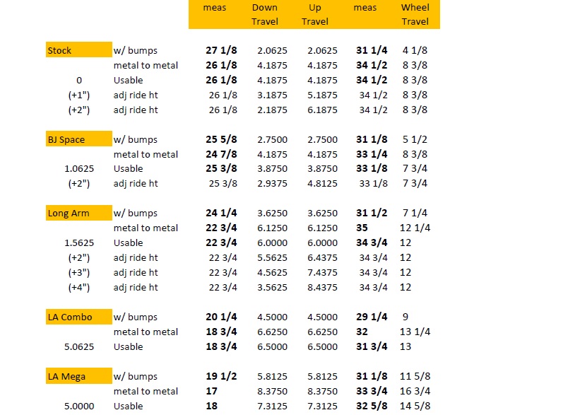
I decided to go ahead and post another spread sheet with additional data. This version includes data for the Long Arm kit, the Combo Long Arm kit, and the Mega Travel Long Arm kit. If you would like to read more about each of these kits you can do some searches here on YT.
The Long Arm kit is in production. It is typically set up to be a 3" lift ride height, but as you can see that is adjustable. The "usable" travel with an equal up/down travel setting would give a 1-1/2" lift and 12" travel. The metal to metal travel (12.25") would get you into trouble with the ball joints if you ran without bump or droop stops. I recommend using the factory stops.
The "Combo" Long Arm kit uses the above kit but in combination with a drop bracket kit. This is not a turn key production kit but the parts to put it together are. In basic form it doesn't provide more travel than the standard long arm kit just additional lift (about 5") In the case of the version the data points were taken from (in the spread sheet) it had a few additional tweaks. The upper ball joint is a custom high angle unit allowing additional up travel. The bump stop "drop brackets" are custom and are set to limit the up travel to the appropriate usable amount. The steering links are custom heim joints that also allow additional travel. And lastly the 4wd components are a CMdiff configuration allowing additional travel.
The Mega Travel kit is only a prototype and only one working model is in use, on my 1986 4 Runner. I have built a second prototype but it is being used for mock up for future production. The MT is a hybrid of the combo kit but with relocated pivot points. As you can see from the spread sheet the metal to metal travel numbers are huge. Unfortunately this has to be scaled back to a less impressive "usable" number, primarily due to steering complications.
I will be out of communication for the next week. I will be in Baja Mexico for the Score Baja 500. I am doing Pit/Chase with Team Psycho. I will address questions and comments next week when I return.
Last edited by BlazeN8; 06-14-2014 at 09:59 PM.
 06-04-2014, 08:31 AM
#22
Registered User

Join Date: Jan 2009
Posts: 245
Likes: 0
Received 0 Likes
on
0 Posts
Great posting, Nate! I was planning on ordering BJ spacers this Friday, now I'm going to have to think on it. Leaving aside the binding issue for now, I thought that I had read somewhere that a company (don't recall but something like 'K----' Fabrication?) makes BJ spacers that do not require UCA surgery.
However, because of BJ spacer-induced strain and binding, the upshot here is that I now have to achieve level with new leaf springs by some other means--by which I mean torsion bar tension.
I never thought of BJ spacers as a particularly great mod, but a frugal way of leveling the vehicle with aftermarket springs while slightly improving travel. Seems like every <$1k solution for our IFS ends up causing problems worse than the stock design.
Any chance you would take a beat-up SFA, a sack of seat belts, and a (quite friendly, good mouser) stray cat for a LT set?
06-04-2014, 10:12 AM
#23
Someone at ORW here in San Diego also said that he's heard of a lot of failures related to BJ spacers. They may be OK for dirt roads/DD, but not for hardcore wheeling that is the reason for installing them in the first place.
Re Torsion bar method:
Old Man Emu uses that to work with their rear leaf lifts, so the company must have done its homework.
It only leaves the question of CV binding.
Nate, I believe you have addressed that with your Long-Travel kit. May we have direct link to general info on that, and how the LT kit addresses CV binding during articulation?
Best wishes on Score Baja 500.
Last edited by RAD4Runner; 06-04-2014 at 10:17 AM.
06-09-2014, 10:33 AM
#25
Registered User
Thread Starter
I know its not as easy as it used to be to "Search" YT for Blazeland info! The problem is if someone just enters the term Blazeland then that keyword search is going to list thousands of keyword finds. Another keyword you can use for a search that comes up with less clutter, try Blazelander2013
I would recommend using the "Advanced Search" options to be more specific and narrow the search. I do list some links for some good YT threads on the subject in the "links page" of the Blazeland website.
The Baja 500 was a DNF for team Psycho this year. We got stuck in traffic in silt beds a number of times and were not able to make the check point time cut off. We made it to mile 220 and turned back to the coast. I believe there was an unusually large number of DNFs this year.
I may post some more information about CV axle binding and shock mounting measurements a bit later.
Last edited by BlazeN8; 06-09-2014 at 05:29 PM.
06-09-2014, 05:09 PM
#26
Registered User
Thread Starter
You guys are on it! Yep, there is more to it than just the ball joint operating limits. The remaining data that would be worth looking at would be:
1) The CV Axle operating limits.
2) The outer tie rod end operating limits.
3) The shock mounting point measurements.
All of these are relevant in maximizing wheel travel and finding the operating limits. These are checks everyone should be performing to determine functionality and safety when they are making suspension modifications. It is likely that in performing these checks you will find a need for additional adjustments to the bump / droop stops. So your not done yet.
Unfortunately, I don't have this information for a "stock rig" or "BJ Spacer rig" scenario. I am curious as to seeing these datum points so I probably will go through the steps eventually. I need to go out back to the junk pile and dig out a stock differential, a stock length CV, and a stock length tie rod adjusting sleeve. I also need to set aside a few hours to install it all onto the frame jig and run through the process.
I was looking through my notes and I could post this additional data for Long Arm, LA Combo, and LA Mega. But, this isn't a direct comparison, so I am not going to post it. In summary:
1) The Long Arm CV Axle has a different center bar length, so its a different geometry. The operating angle of the joints is the same but longer CV center bar = more wheel travel. The Combo and Mega use a CMdiff so the center bar is even longer = no contest.
2) The shock angle for the LA is much greater, so it creates a different ratio within a shock. And the shock used in the LA is 4" longer. The Combo has a drop bracket and spindle spacer, so the measurement comparison is even more irrelevant. The Mega use a shock hoop, so nothing is familiar.
3) The outer Tie Rod End "angle" for the LA, Combo, and Mega isn't a relevant comparison because the longer length Tie Rod Adjusting Sleeve. Same concept as the longer center bar in the CV axle assembly. For the Combo and Mega the geometry comparison is even more complicated because the drop bracket spindle spacer relocates the steering arm. The Mega uses a different center link and pivot points so its totally alien.
06-11-2014, 03:03 PM
#27
Registered User
Thread Starter
Got some more measurements. I am going out of sequence and starting with the shock mounting point measurements.
Starting at the LCA, I measured from the center line of the shock tab up to the bottom face of the mounting bracket at the frame. Here are the results.
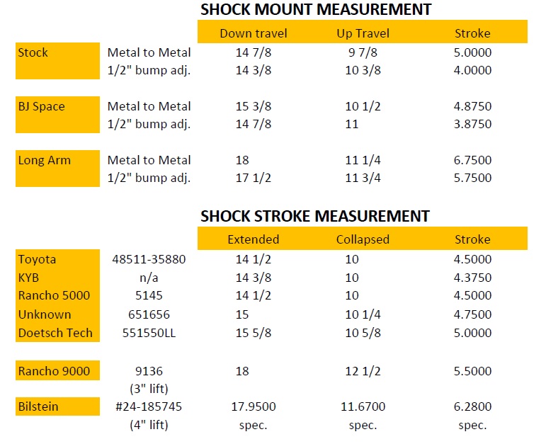
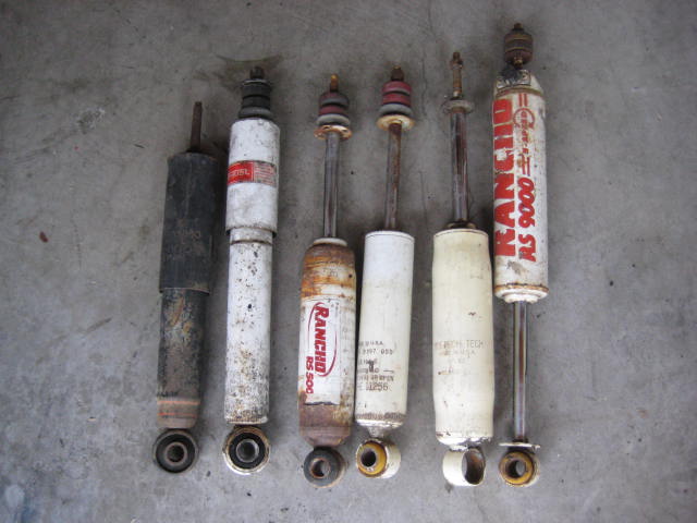
Next, I was able to dig up (5) shocks designed to fit a stock suspension. The 6th one, the Rancho RS 9000 was designed to fit the old and discontinued Rancho 3" lift kit. The 7th (not pictured) is designed to fit a Truck/4Runner with a 4" lift. This is also the shock I recommend for the Long Arm Kit.
The theory is to find a shock to work within the shock mounting point measurements. In the best case scenario you want it to work within the metal to metal measurement, or at least within the working limits. However the best case scenario may not be available. It may be acceptable to use a shock that works within the range when bump / droop stops are installed, but you need to compensate for bump / droop stop compression. For this adjustment I allowed 1/2". Also note: The shock itself, with rubber bushings at the eye and pin mount, does allow some compression in the bushings.
The worst case scenario is the shock length specifications are beyond the mounting point measurements to a degree that causes the shock to become the bump stop or limit strap of the suspension.
If a shock cannot be found that will work in the above mentioned you should revisit the bump / droop stop configuration. Shimming or replacing the stops will reduce wheel travel but it will protect the shocks from being damaged.
Starting at the LCA, I measured from the center line of the shock tab up to the bottom face of the mounting bracket at the frame. Here are the results.
Next, I was able to dig up (5) shocks designed to fit a stock suspension. The 6th one, the Rancho RS 9000 was designed to fit the old and discontinued Rancho 3" lift kit. The 7th (not pictured) is designed to fit a Truck/4Runner with a 4" lift. This is also the shock I recommend for the Long Arm Kit.
The theory is to find a shock to work within the shock mounting point measurements. In the best case scenario you want it to work within the metal to metal measurement, or at least within the working limits. However the best case scenario may not be available. It may be acceptable to use a shock that works within the range when bump / droop stops are installed, but you need to compensate for bump / droop stop compression. For this adjustment I allowed 1/2". Also note: The shock itself, with rubber bushings at the eye and pin mount, does allow some compression in the bushings.
The worst case scenario is the shock length specifications are beyond the mounting point measurements to a degree that causes the shock to become the bump stop or limit strap of the suspension.
If a shock cannot be found that will work in the above mentioned you should revisit the bump / droop stop configuration. Shimming or replacing the stops will reduce wheel travel but it will protect the shocks from being damaged.
06-12-2014, 07:53 PM
#28
Registered User
Thread Starter
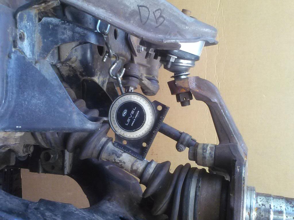
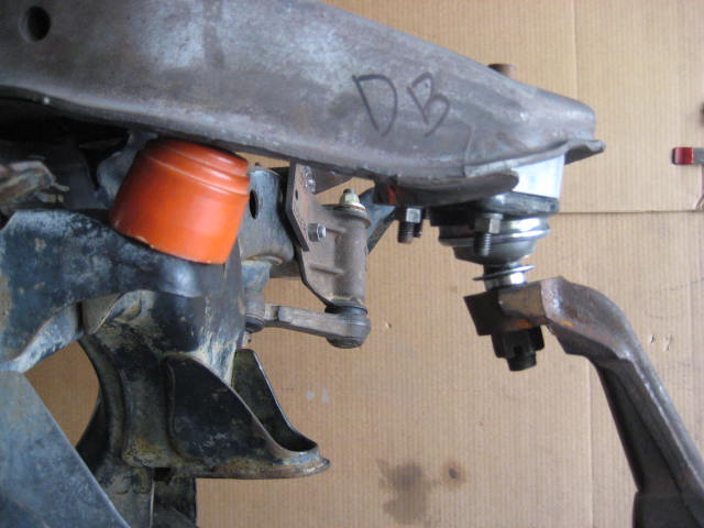
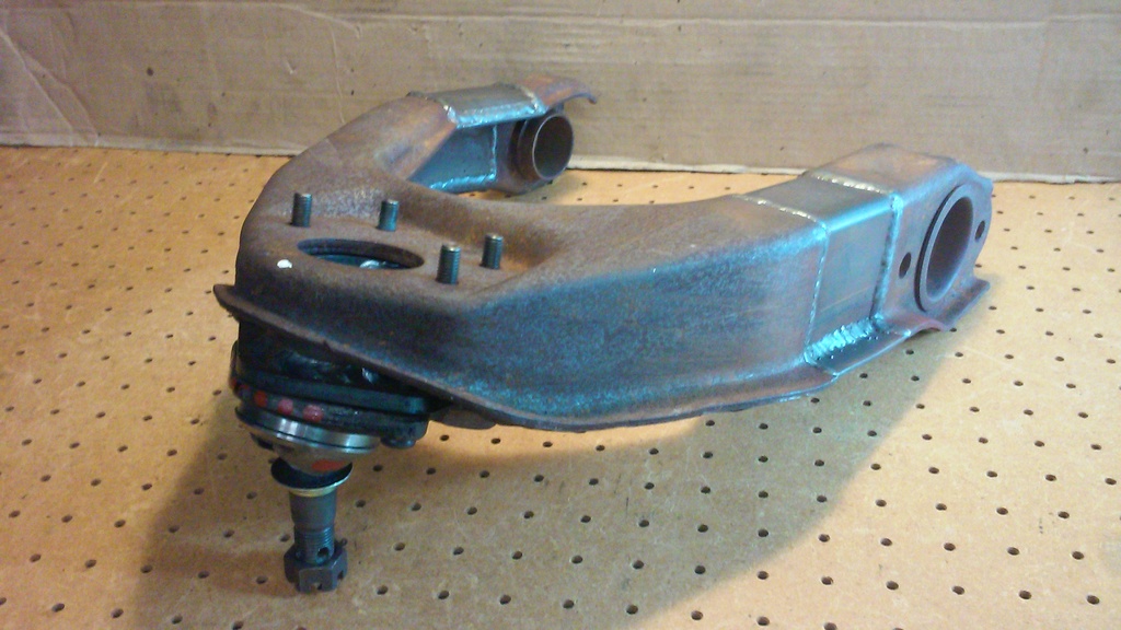
Next up, the outer Tie Rod End operating limits. I found the angle of operation to be 50 degrees for the total range. It can go 30 degrees past horizontal when cycling to the down travel position.
At the up travel position it can go 20 degrees past horizontal.
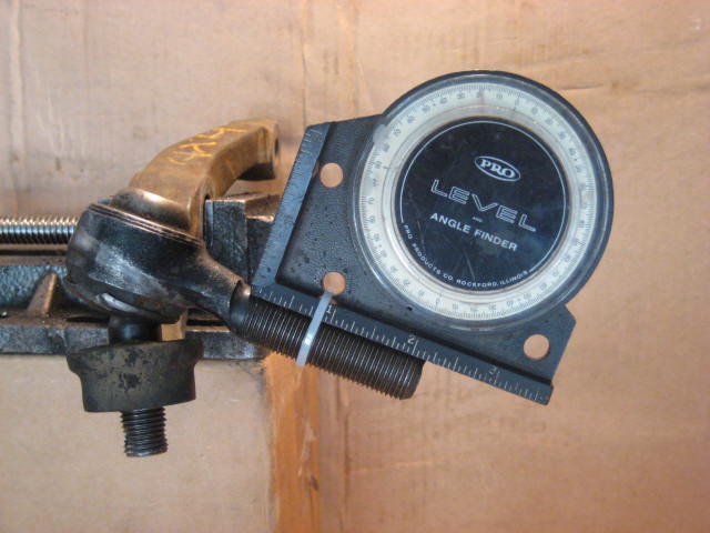
I then installed the steering linkage to the frame jig and cycled the suspension with the desired configurations in a metal to metal setting.
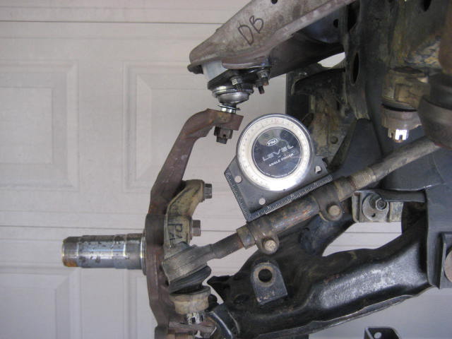
Pictured below is the suspension with BJ Spacer at droop. I found the angle to be 30 degrees. Bind occurs at 30 degrees so the Tie Rod End is maxed out and at risk of binding.
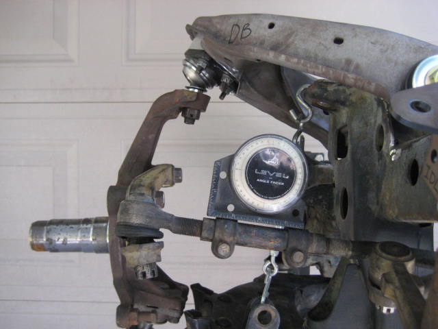
Here is the suspension with BJ Spacer at stuff. I found the angle to be 8 degrees. Bind would occurred at 20 degrees.
I took measurements for three suspension configurations and recorded the data onto the following spreadsheet.
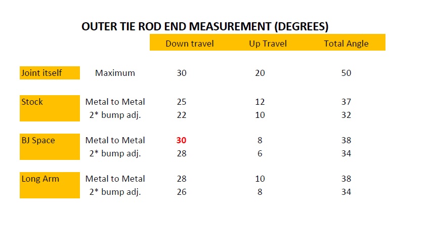
From crunching the numbers you can see the Outer Tie Rod End is at risk of binding when the suspension is at full droop with the BJ Spacers installed. However if I allow a 2 degree adjustment for adding bump / droop stops the angle is less dramatic.
At the up travel position it can go 20 degrees past horizontal.
I then installed the steering linkage to the frame jig and cycled the suspension with the desired configurations in a metal to metal setting.
Pictured below is the suspension with BJ Spacer at droop. I found the angle to be 30 degrees. Bind occurs at 30 degrees so the Tie Rod End is maxed out and at risk of binding.
Here is the suspension with BJ Spacer at stuff. I found the angle to be 8 degrees. Bind would occurred at 20 degrees.
I took measurements for three suspension configurations and recorded the data onto the following spreadsheet.
From crunching the numbers you can see the Outer Tie Rod End is at risk of binding when the suspension is at full droop with the BJ Spacers installed. However if I allow a 2 degree adjustment for adding bump / droop stops the angle is less dramatic.
Last edited by BlazeN8; 06-12-2014 at 08:11 PM.
06-16-2014, 09:04 PM
#29
Registered User
Thread Starter
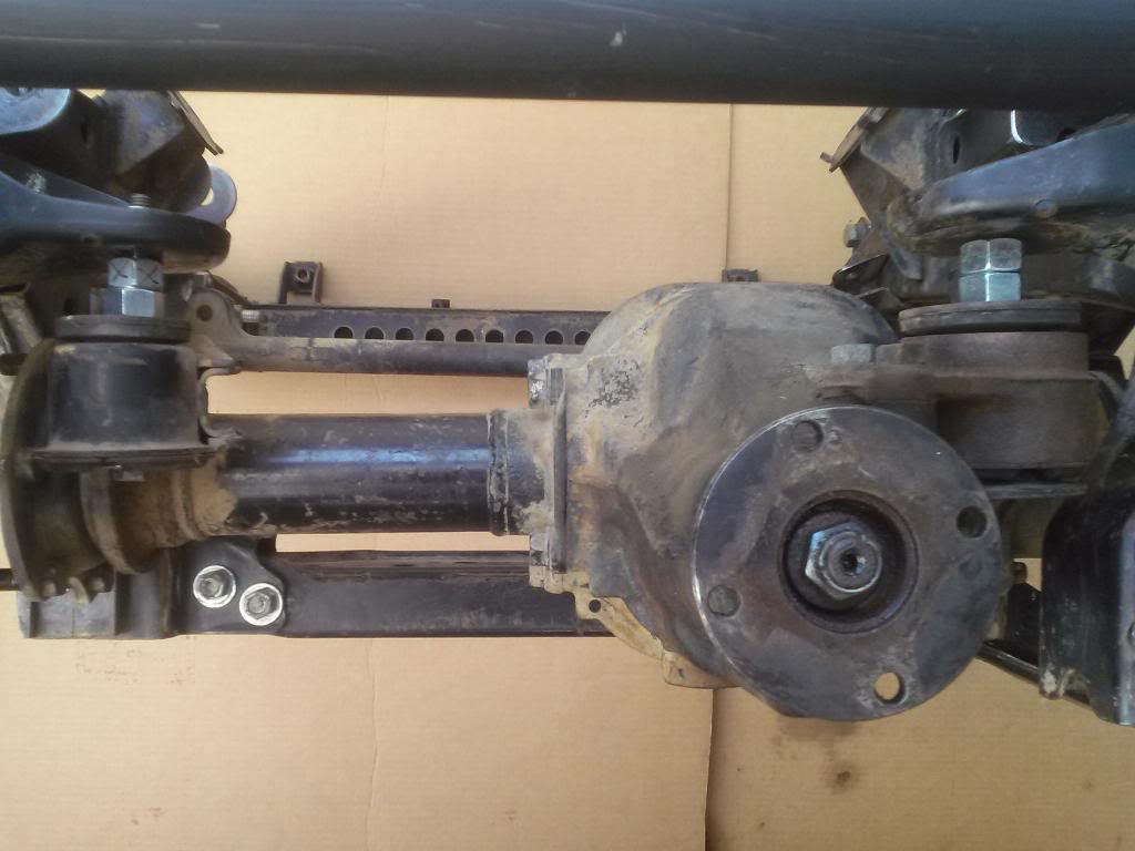
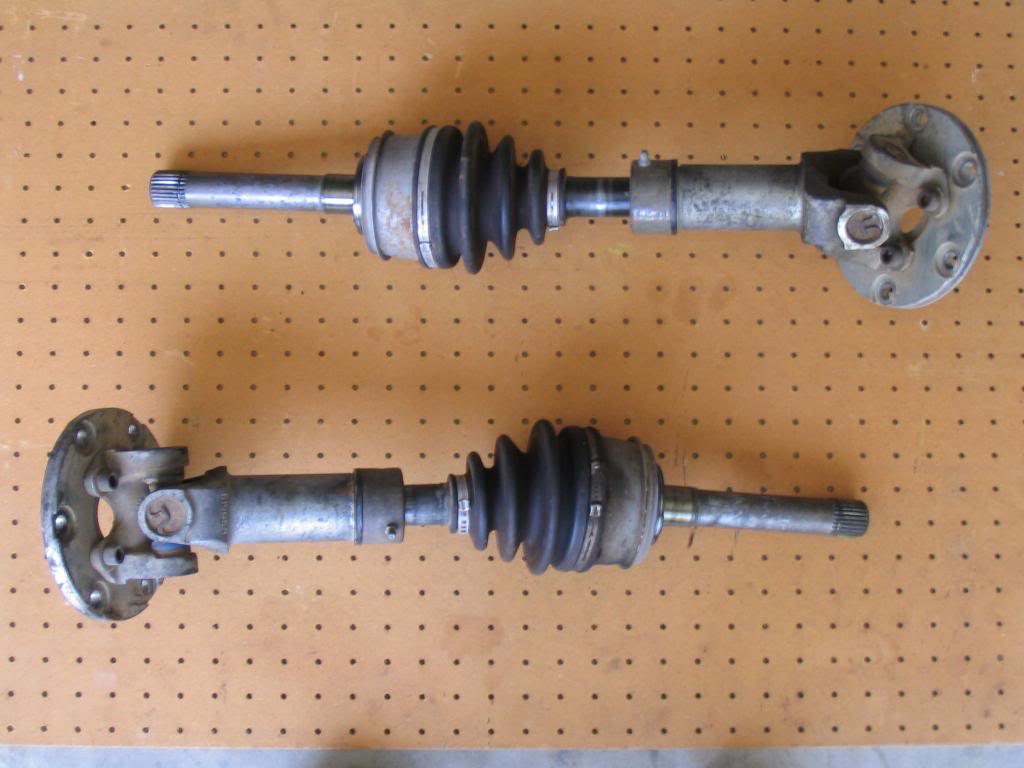
Today I had a few hours to kill so I mocked up the CV Axle for functionality with regards to BJ Spacers. I found that the CV Axle began to bind at 25 degrees below horizontal. That is 5 degrees sooner than the outer Tie Rod End. It is common knowledge that CV Axles are the limiting factor to wheel travel, so this really isn't a surprise. If you examine the photo you can see the distance between the bottom of the UCA and the droop stop frame bracket to be nearly an inch.
There is no way to force a metal to metal condition as the inner tripod bottoms out on the bottom of the barrel. The plunge is all used up. I then backed off on the amount of droop till the CV began to rotate. As it rotates you can see the joint deflects and as it does you can feel resistance. In one rotation you can see and feel this three times, due to the tripod design. What is happening is the center bar axle is hitting the side of the barrel. If this happens with enough force the barrel will split or the joint will lock up. When the joint locks up the rotation stops and the axle shaft snaps.
A less dramatic condition that occurs, at less extreme CV angles is the rubber boot ruptures and you get that nasty axle grease flinging all over your under carriage.
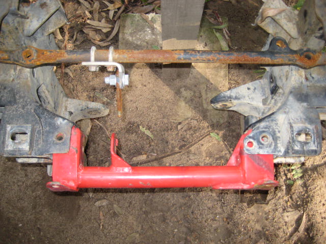
A common band aid I see people trying is "dropping" the differential to reduce the CV angles. I have seen people install longer bolts and 1" spacers. I think there is a company or two selling this in kit form but the basic premise can be replicated for mock up purposes as I did with a couple of 5/8" nuts.
the LH side mount
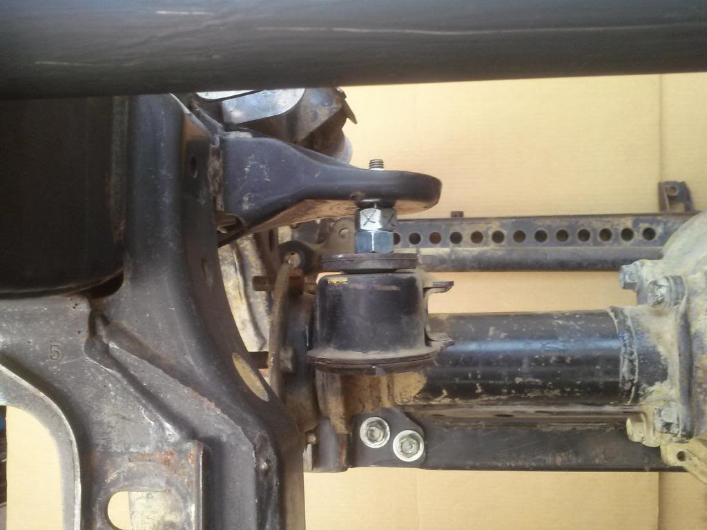
and the RH side mount
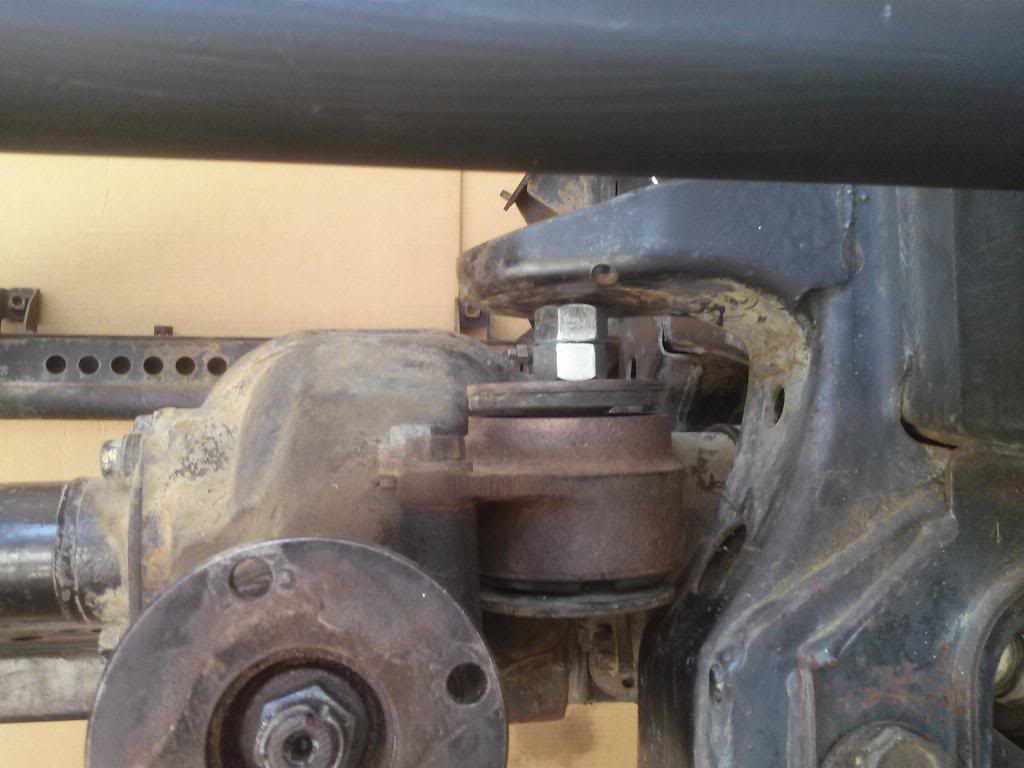
The problem is there is no lowering at the front mount. This is like cutting off two legs of a three legged stool. This isn't lowering the diff by one inch because the front mount just pivots. The actual lowering of the diff at the location of the RH and LH flange attachment is only fractions of an inch. I wasn't even able to see any change in the angle at the CV axle when I took another measurement with the angle finder. Where the diff actually lowers close to an inch is at the input flange that connects to the front drive shaft. All that does is increase the drive shaft angle, pointless!
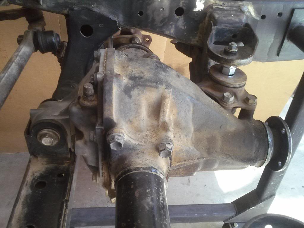
If your wanting to allow proper functioning of the CV Axles with BJ Spacers your going to have lower the differential more than fractions of an inch like the old Rancho kit did with an all new front cross member and RH / LH brackets (not shown).
Rancho also added a rear cross member for more strength.
The drawback of lowering the diff like this is loss of ground clearance. Downey's solution was to install some slip yoke, high angle CVs and keep the diff in the factory location.
The above solutions are not cost effective to a BJ Spacer budget builder, so it looks like its back to the big, thick droop stops.
There is no way to force a metal to metal condition as the inner tripod bottoms out on the bottom of the barrel. The plunge is all used up. I then backed off on the amount of droop till the CV began to rotate. As it rotates you can see the joint deflects and as it does you can feel resistance. In one rotation you can see and feel this three times, due to the tripod design. What is happening is the center bar axle is hitting the side of the barrel. If this happens with enough force the barrel will split or the joint will lock up. When the joint locks up the rotation stops and the axle shaft snaps.
A less dramatic condition that occurs, at less extreme CV angles is the rubber boot ruptures and you get that nasty axle grease flinging all over your under carriage.
A common band aid I see people trying is "dropping" the differential to reduce the CV angles. I have seen people install longer bolts and 1" spacers. I think there is a company or two selling this in kit form but the basic premise can be replicated for mock up purposes as I did with a couple of 5/8" nuts.
the LH side mount
and the RH side mount
The problem is there is no lowering at the front mount. This is like cutting off two legs of a three legged stool. This isn't lowering the diff by one inch because the front mount just pivots. The actual lowering of the diff at the location of the RH and LH flange attachment is only fractions of an inch. I wasn't even able to see any change in the angle at the CV axle when I took another measurement with the angle finder. Where the diff actually lowers close to an inch is at the input flange that connects to the front drive shaft. All that does is increase the drive shaft angle, pointless!
If your wanting to allow proper functioning of the CV Axles with BJ Spacers your going to have lower the differential more than fractions of an inch like the old Rancho kit did with an all new front cross member and RH / LH brackets (not shown).
Rancho also added a rear cross member for more strength.
The drawback of lowering the diff like this is loss of ground clearance. Downey's solution was to install some slip yoke, high angle CVs and keep the diff in the factory location.
The above solutions are not cost effective to a BJ Spacer budget builder, so it looks like its back to the big, thick droop stops.
06-16-2014, 10:06 PM
#30
Today I had a few hours to kill so I mocked up the CV Axle for functionality with regards to BJ Spacers...
The problem is there is no lowering at the front mount...Where the diff actually lowers close to an inch is at the input flange that connects to the front drive shaft. All that does is increase the drive shaft angle, pointless!

The problem is there is no lowering at the front mount...Where the diff actually lowers close to an inch is at the input flange that connects to the front drive shaft. All that does is increase the drive shaft angle, pointless!
Last edited by RAD4Runner; 06-17-2014 at 01:02 PM. Reason: edit" "or actually does NOT work..."
06-17-2014, 12:34 PM
#31
Registered User
Join Date: Jan 2009
Posts: 245
Likes: 0
Received 0 Likes
on
0 Posts
Thanks, again, Nate! I'm kinda shocked that your set-up and tests haven't already been done, here. It's really great to see some hard data produced in a controlled manner.
I'm probably like a lot of YT guys in that I'm constantly looking to save money on building the rig. For me this is a necessity and a passion! Unfortunately, this approach can lead to less-than-great compromises.
I'm probably like a lot of YT guys in that I'm constantly looking to save money on building the rig. For me this is a necessity and a passion!
Unfortunately, this approach can lead to less-than-great compromises.
06-17-2014, 02:28 PM
#32
Registered User
Nate, I've personally seen your truck and enjoyed your conversations at Pismo. I still say I'd love to see you put your meticulous engineering skills towards a Solid Axle setup. I'm sure you could do a beautiful job.
06-17-2014, 02:30 PM
#33
I like what you're doing with all these tests. It's nice to finally be able to SEE what's happening with the different IFS changes vs being in the dark and taking a company's word without proof. Looking forward to seeing the results of the next tests.
06-17-2014, 03:12 PM
#34
Registered User
Thread Starter
Thanks guys! I'm not sure I am needing to do anymore test on this thread! I think I have covered most of the pertaining items! My goal was to provide the information and share the tech. When you go to make changes think it through and do the research. You've seen the process, do some of your own checks next time you install the various components.
Mak, see you at Pismo this year? So many company's doing the SAS all ready. Besides I have my 1985 P/U to tweak on here and there to get the concepts. I know the pros and cons between the two systems and the IFS just suites my driving preferences. If I lived in your neck of the woods I might be motivated to build a crawler with a live axle. I just like desert and dunes the best! Long Travel and a lead foot is so much fun!
Mak, see you at Pismo this year? So many company's doing the SAS all ready. Besides I have my 1985 P/U to tweak on here and there to get the concepts. I know the pros and cons between the two systems and the IFS just suites my driving preferences. If I lived in your neck of the woods I might be motivated to build a crawler with a live axle. I just like desert and dunes the best! Long Travel and a lead foot is so much fun!
Last edited by BlazeN8; 06-17-2014 at 03:53 PM.
06-30-2015, 01:54 AM
#35
Registered User

Join Date: Apr 2015
Location: Sydney
Posts: 2
Likes: 0
Received 0 Likes
on
0 Posts
Sorry to drag up an old thread, but would it be possible to incorporate an uni-ball joint into the spacer, construct the spacer in such a way that there's not cutting required to the UCA ?
Can you run a mix of uni ball joint & standard type ball joints ?
Just throwing an idea around.
Can you run a mix of uni ball joint & standard type ball joints ?
Just throwing an idea around.
06-30-2015, 06:52 AM
#36
Registered User
Join Date: Jun 2009
Location: Virginia Beach, VA
Posts: 572
Likes: 0
Received 0 Likes
on
0 Posts
this is so incredibly informative. I will no longer be buying BJs and now I have to find a way to slowly acquire a blaze LT kit and hide it from the fiance
08-01-2015, 04:47 PM
#37
Registered User
Thread Starter
Ozzyrob,
Yeah, that's cool, I like throwing around ideas too! Obviously! Anyway, you might want to check out Rough Road Fabrication http://www.roughroadfabrication.com/Parts.html This outfit offers an upper BJ to uni-ball conversion but it doesn't look like it would work in combination with a BJ Spacer as the bolt head would contact the inner diameter of the spacer. Could a reconfigured BJ Spacer be made to solve the fitment issues and do away with clearance work needed at the UCA, perhaps? However, as I showed throughout this thread, changing the pivot location of the ball makes no sense anyway you look at it. I can see RRF's uni-ball conversion being something to look into, but not as a way to space the ball pivot location.
It is possible RRF's uni-ball conversion would fit within the Blazeland UCA Extension Bracket? RRF's design looks to be as simple as attaching laser cut tabs to a standard uni-ball cup. However, even a uni-ball has a limited range, so the uni-ball cup and the tabs being at a right angle to each other, the sweep may not be optimal in its starting and ending relation to the mounting surface plane. When I sent Howe Racing a care package to have their engineers work their magic this became a problem. Machining a uni-ball cup with a (4) bolt flange to fit the Toyota UCA was not the problem it was maching an angle in the assembly to maximize the starting and ending point of the sweep. The factory upper BJ incorporates an angle with the mounting flange. In addition to that the ball stud pivots within a slot rather than a round opening so it can attain a high angle.
It is a bit difficult to explain all this in a few paragraphs. Sorry if I am confusing the issue.
08-01-2015, 07:08 PM
#38
Registered User
Thread Starter
Speaking of a BJ Spacer that will work without carving up the UCA, I did build one a while back. Again with the terminology, I would not call it a BJ "Spacer" I would call it a BJ "Adapter" for reasons I described earlier in this thread. This design relocates the ball joint 1-1/2" vertical and 1/2" horizontal from the mounting point plane. The horizontal distance means no need to carve into the UCA but it means the LCA needs to be lengthened. In my case I lengthened the UCA 3" plus the 1/2" for the "adapter" giving an overall lengthening of 3-1/2" to match a Long Arm LCA.
The advantage of lengthening the UCA rather than just using the UCA Extension Bracket is it allows a bigger, longer shock or coil over conversion to be located within the UCA rather than behind it. Unfortunately the lengthened UCA still needs a vertical ball joint relocation to allow proper down travel so its even more work because I'm lengthening a UCA and building a bracket. The cool factor is I actually found a good use for the BJ Adapter Bracket.
The advantage of lengthening the UCA rather than just using the UCA Extension Bracket is it allows a bigger, longer shock or coil over conversion to be located within the UCA rather than behind it. Unfortunately the lengthened UCA still needs a vertical ball joint relocation to allow proper down travel so its even more work because I'm lengthening a UCA and building a bracket. The cool factor is I actually found a good use for the BJ Adapter Bracket.
08-09-2015, 05:08 PM
#39
Registered User

Join Date: Jun 2015
Location: Ridley, PA
Posts: 47
Likes: 0
Received 0 Likes
on
0 Posts
5" Lift Kit 91' Pickup DLX V6 4x4...... GRINDING in my Front Axel!
3 Mechanics ----- 3 different diagnosis.
After I blew $150 replacing front left Hub... Grinding reduced but still exists.
Do I need to install Differential Drop Spacers?
3 Mechanics ----- 3 different diagnosis.
After I blew $150 replacing front left Hub... Grinding reduced but still exists.
Do I need to install Differential Drop Spacers?
08-09-2015, 08:57 PM
#40
Registered User
Thread Starter
You should start a thread of your own to discuss this topic. Posting such a broad question on this thread is considered hijacking. It is off topic and interrupts the continuity. I think you would get a much better participation on your own thread. I suggest you take some photos and describe what is going on in detail. List the three different diagnostics the three mechanics came up with. I would be glad to chime in on your post once its created and details are provided.
My initial though would be if there was no grinding before the hub blew and you repaired the hub, something else was damaged. Jack up the front and cycle the suspension and do the test like I did in this build thread while spinning the axle and find what is grinding or binding. If you have BJ Spacers or low profile bump or droop stops, you may be exceeding the specifications of the CVs? Really though I think this would be better handled on your own thread with more information provided. Best of luck!
My initial though would be if there was no grinding before the hub blew and you repaired the hub, something else was damaged. Jack up the front and cycle the suspension and do the test like I did in this build thread while spinning the axle and find what is grinding or binding. If you have BJ Spacers or low profile bump or droop stops, you may be exceeding the specifications of the CVs? Really though I think this would be better handled on your own thread with more information provided. Best of luck!


