When you click on links to various merchants on this site and make a purchase, this can result in this site earning a commission. Affiliate programs and affiliations include, but are not limited to, the eBay Partner Network.
Excuse for a Rod Trip :) Cooling System Heavy-Duty Flush
"Heavy-Duty" Flush, in Prestone's words...
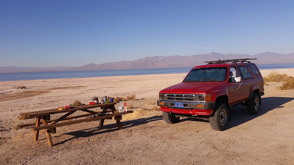
Drained system and thoroughly rinsed. Refilled with plain water and flushing solution. Drove from Riverside County to Anza-Borrego desert, to camp in Salton Sea, then finally to Salvation Mountain and Slab City.
Memorial for friend who passed away while driving out of the Anza-Borrego desert after easy exploration:
Salt Creek Primitive camp on northeast shore of Salton Sea I had the whole beach to myself
Cooling System: "Heavy-Duty" Flush And THOROGHLY Cleaning Temp Sensors
After road-trip to Anza-Borrego Desert and Salton Sea (Heavy-Duty Flush)
I did the following (temp gage sender is not very accessible and I do not see issues with it so I did not clean that one):
Removed thermostat, cleaned thermostat housing, cold start injector timer switch, coolant temp sensor (ECU), temp gage sender, and the coolant temp sensing vacuum switching valve (I'll research official name later). Installed 2-stage thermostat. Also tested the CSI timer switch (brown connector) and coolant temp sensor (green connector).
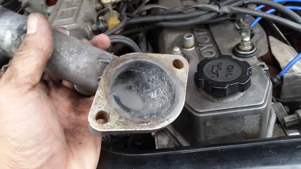
Thermostat housing has lots of scaling. Picture shows after I soaked it in vinegar and steel-brushed. Although not that critical, I think that every little thing we do to help the cooling system is good.
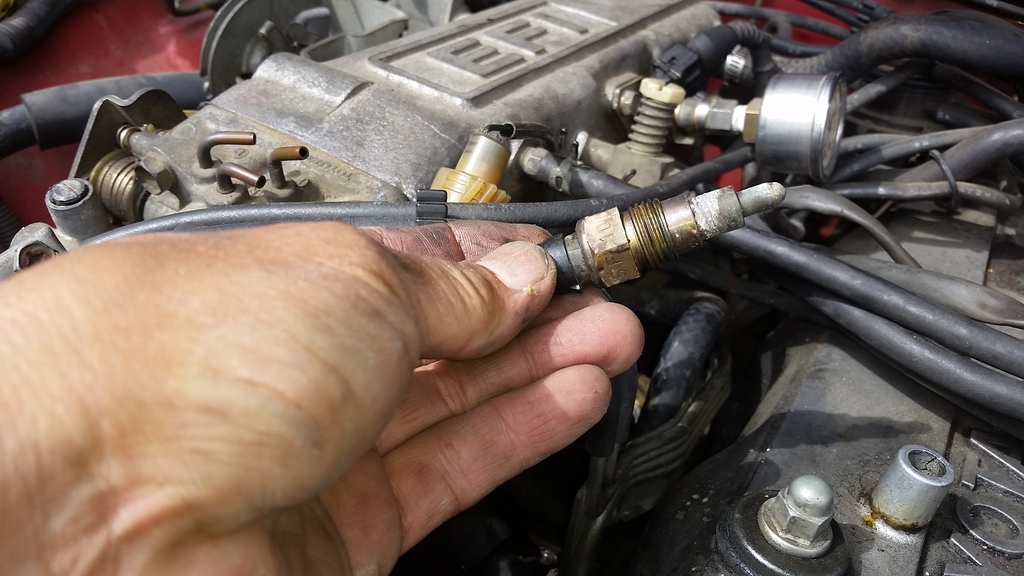
Scale on threads for CSI timer switch. Contact between clean bare metal of CSI timer switch housing and shiny bare metal of engine block is critical because CSI timer switch provides ground to CSI in order to turn it on.
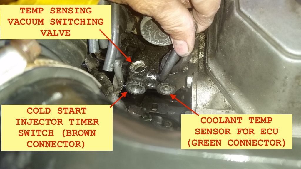
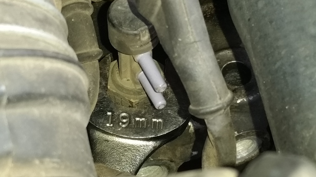
Location of temp-sensing VSV and sensors:
Also shows shiny, silver metal on threads for CSI timer.
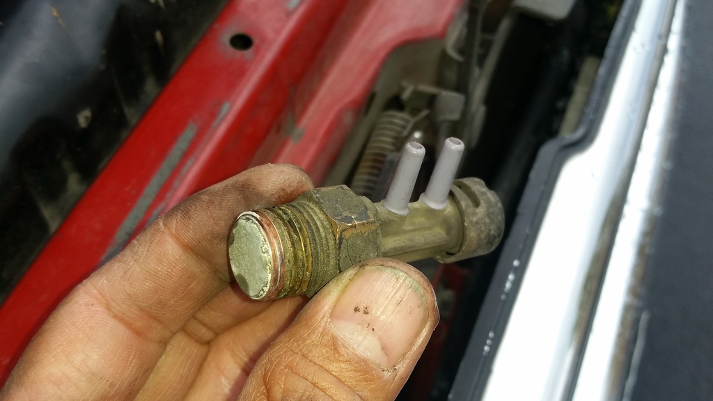
Badly scaled. I think this does not allow it to read temperature accurately. May contribute to hard cold start. (EGR Control? Would appreciate info on this).
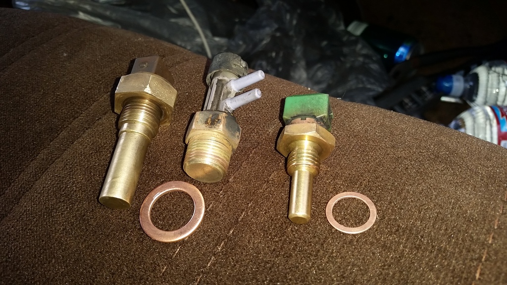
Coolant Thermo Switch (TSW) also badly scaled:
Cleaned:
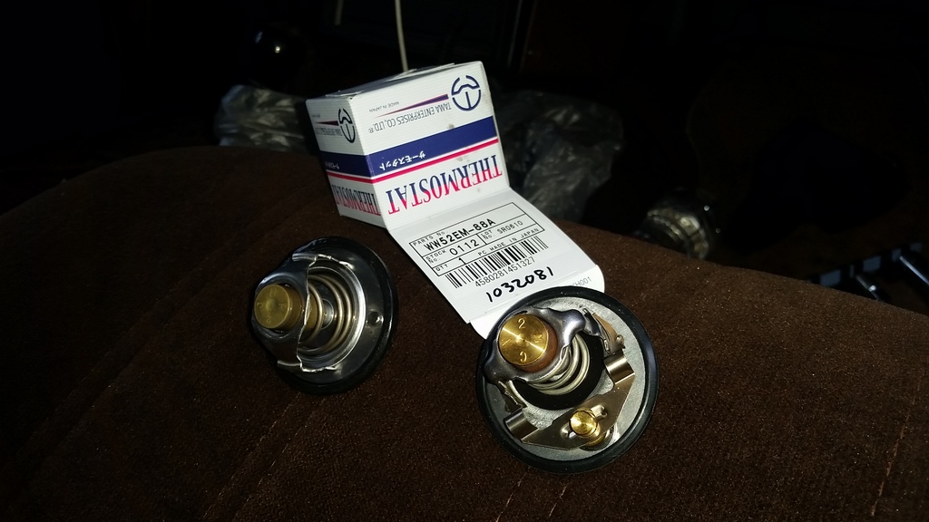
Replaced original (left) thermostat with the 2-stage thermostat from LC Engineering. According to LCE, TAMA makes the 2-stage thermostat for Toyota. I paid $40 plus shipping for this. Other stores may carry same TAMA P/N for less.
TAKE-AWAYS:
I think the following would help with my hard cold stars:
Thorough cleaning of the CSI timer switch housing and the receiving thread because that's where CSI timer switch grounds on terminal of the CSI in order to actuate it.
Thorough cleaning of the temp-sensing vacuum switching valve because it may affect idle. Would appreciate correction if I'm wrong.
Chemical flushing of cooling system alone may not be enough. Best to mechanically clean (steel-brush, etc) accessible parts.
CONCERN:
I tested the CSI timer switch:
STA - STJ, STA-GND readings were good.
However, FSM does not list spec for STJ to GROUND. This is actually the more critical spec because CSI timer switch grounds negative side of CSI during cold cranking in order to activate the CSI. Anyway I measured it at 68�F and STJ to GND read 16 ohms, but later after sitting around, it read 125 ohms! In the morning before I re-installed it it read around 40ohms. This unit could be going bad.
WOULD APPRECIATE INFO ON CORRECT SPEC FOR STJ TO GROUND ON CSI TIMER SWITCH.
Last edited by RAD4Runner; 02-19-2018 at 06:03 AM.
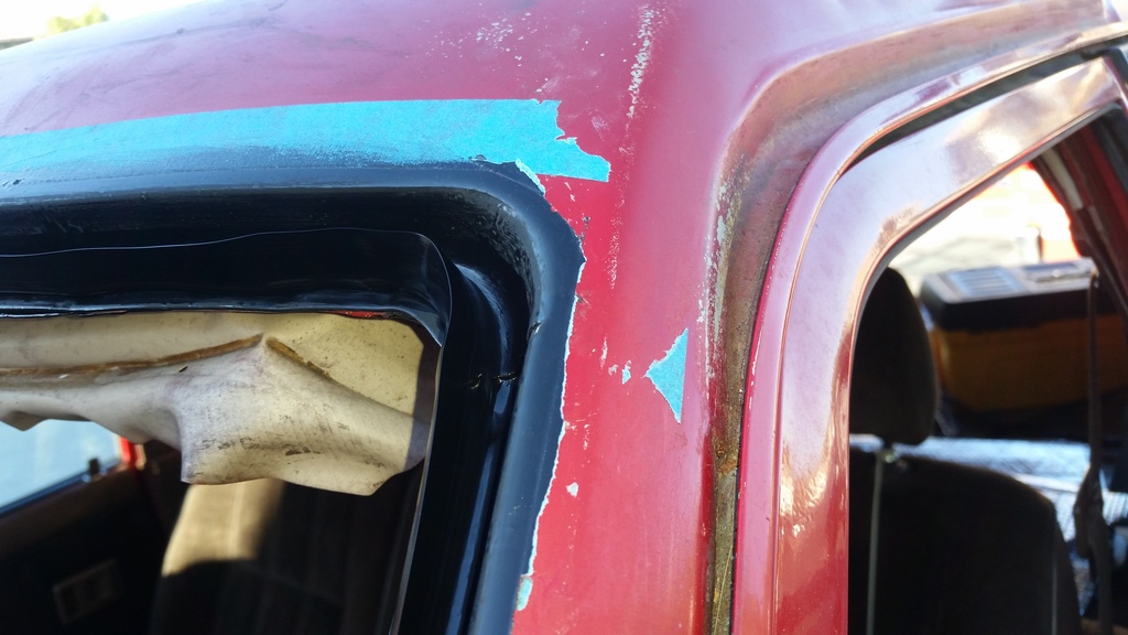
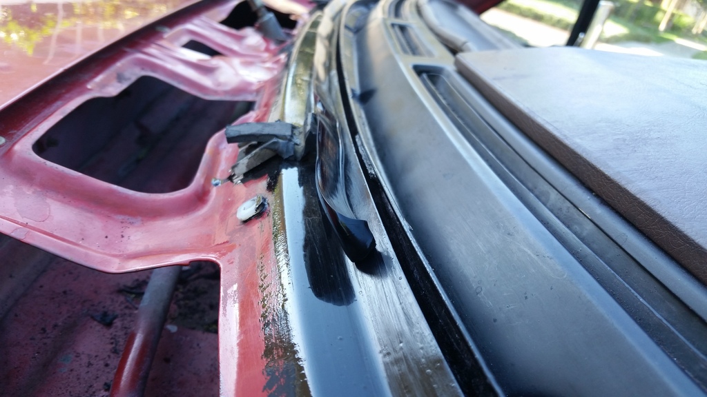
MY PROCESS FOR TOTALLLY ELIMINATING RUST-PROMOTING WINDSHIELD TRIM - NO CHROME NOR RUBBER TRIM THAT TRAPS MOISTURE AND DIRT.
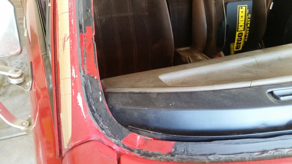
Adhesive was not sticking to the spray paint- repaired surfaces. This time I did a thorough prep.
As you can see, the rusted spots are were clips for the stupid chrome trim trapped dirt and moisture. That is why I detest the chrome trim with a passion!
This time I used POR-15 Starter Kit:
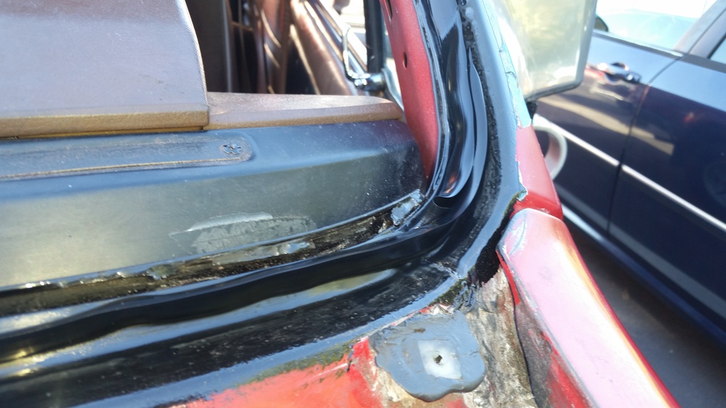
I removed all finish and most rust on the pinch weld and its sidewalls with a steel-brush.
Steel brush does not completely remove loose (brown) rust (merely glazes over it and makes it seems like you had hit bare metal) so I used tiny grinding wheels (part of Dremel-style kit) that I attached to my drill. This removed all the loose, brown rust, and I was left with tiny spots of grey metal where there was pitting. I think POR-15 would take care of sealing that.
A video of the pinch weld in process. I would further grind the brown, loose rust from pitted areas is HERE.
I used POR degreaser and then Metal Prep, then applied 3 coats of POR-15 (waited for each coat to get tacky before applying next coat). I was too busy to take picture of the POR'ed pinch weld and wall, but here's one already with bead of Sika brand windshield adhesive on it...
A picture of bead being applied to bottom pinch weld. Bead is pretty thick so I hope that helps with sealing.
Glass now installed:
Adhesive squeeze-out completely fills underneath edge of the glass.
NEXT STEPS:
Prime the POR-treated area inside the gap, feather the POR and paint on the lip, then repaint.
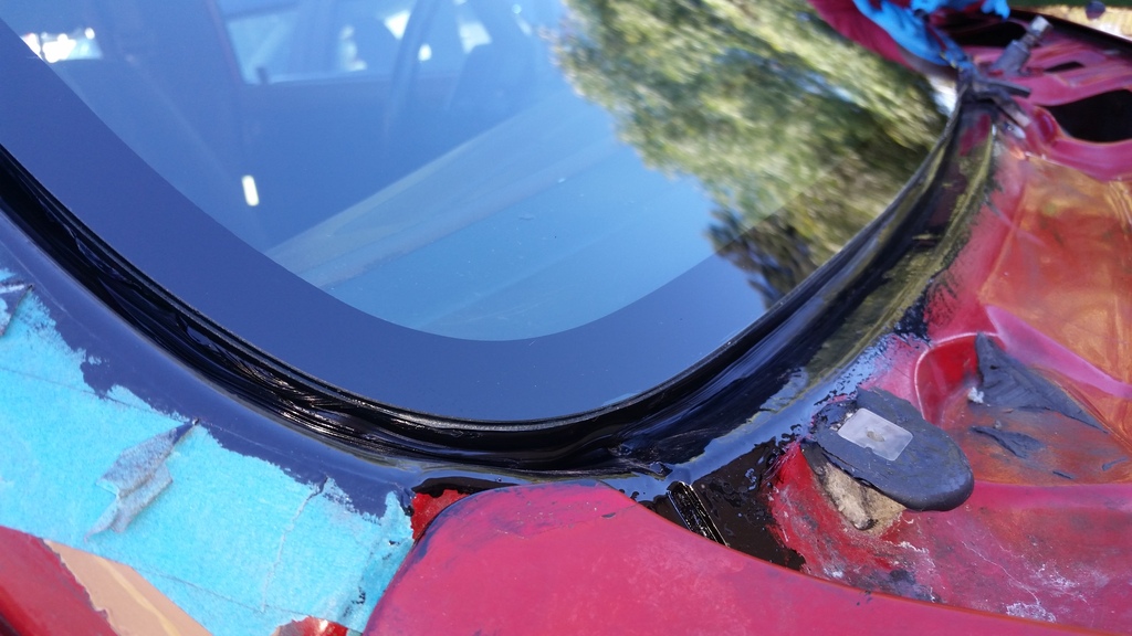
Adventures got in the way, so ALMOST 4 YEARS LATER (LOL!) I FINALLY HAD THE CHANCE TO FILL GAP AROUND THE WINDSHIELD WITH BLACK SILICONE.
Lessons Learned:
1) Paint the POR-15 as soon as cured to protect it from the elements, AND
2) When applying silicon sealant, squeegee it right away - before it forms a "skin"
See below.
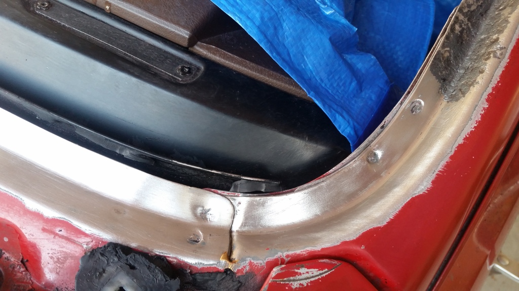
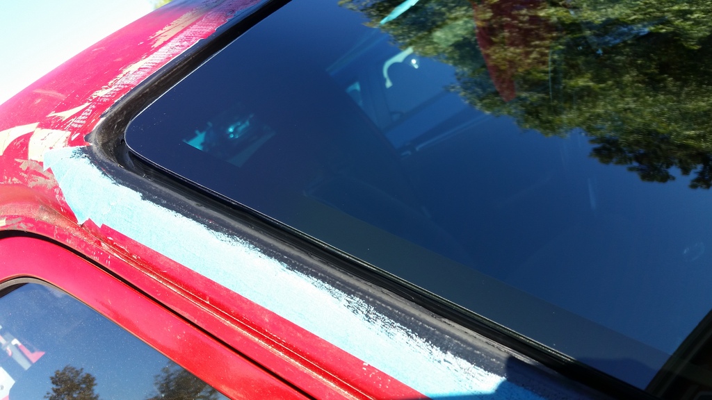
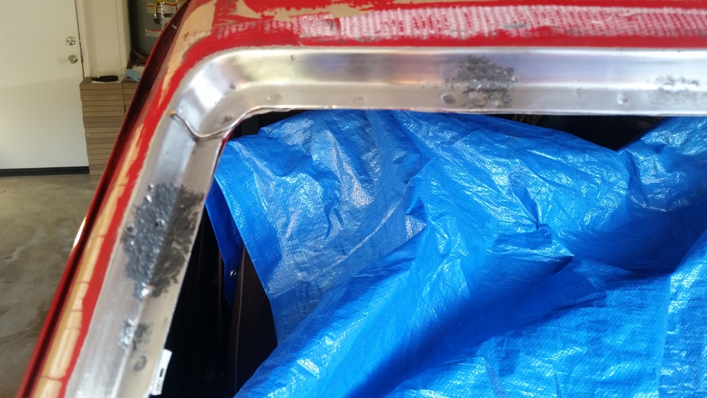
POR-15 HAD DETERIORATED AND SOME EXPOSED METAL HAD RUSTED SO I HAD TO PREP AND PAINT THE METAL AGAIN. I MASKED THE GLASS AND THE URETHANE ADHESIVE SO SILICONE WOULD BOND DIRECTLY TO IT.
POR-15 HAD DETERIORATED AND SOME EXPOSED METAL HAD RUSTED SO I HAD TO PREP AND PAINT THE METAL AGAIN. I MASKED THE GLASS AND THE URETHANE ADHESIVE SO SILICONE WOULD BOND DIRECTLY TO IT.
POR-15 HAD DETERIORATED AND SOME EXPOSED METAL HAD RUSTED SO I HAD TO PREP AND PAINT THE METAL AGAIN. I MASKED THE GLASS AND THE URETHANE ADHESIVE SO SILICONE WOULD BOND DIRECTLY TO IT.
Since there is no longer a trim to hold down / finish the rear edge of cowl cover I did the following:
Last edited by RAD4Runner; 09-25-2020 at 11:37 PM.
Ray - I know you are busy with this windshield, but do you have any more insights into your warm start issue? I have an annoying warm start issue where if engine sits for maybe > 30 minutes but is still warm it doesn't want to start and I usually have to step on the gas to get it to actually start. I see a lot of people looking into similar warm start issues, but there never seems to be a definitive cause. FPU, cold start timer, leaky injector or CSI...but nobody ever seems to get the problem to go away completely. My truck starts instantaneously when cold, even when sitting for weeks it just starts right up and runs fine. My idle air control valve works, I don't believe I have any vac leaks, my tune-up is not exactly fresh, but as far I can remember the truck has had this issue. Anyway, just wanted to see if you have managed to solve your issue.
Sad to see you are still having problems with this. I'm surprised that others are not really having similar issues. Is there not a product that is very tacky and goes on thick to lay on the frame and set the window on?
Thanks, Gevo.
The glass shop uses a urethane adhesive (here) Looks like SIlicone but stronger.
It just so happened that the stuff did not stick well to the paint repair that I did.
I hope it will stick to the POR-15 that I just finished applying tonight.
...do you have any more insights into your warm start issue? I have an annoying warm start issue where if engine sits for maybe > 30 minutes but is still warm it doesn't want to start
Hi, Cory.
I had hard cold starts more consistently for several months. Hard warm starts after parking for sometime was very rare on mine. However, I think those two are temp-dependent.
One thing I highly recommend is to clean al your temp sensors and port where they go into (No Teflon tape on the CSI timer switch most especially), if you haven't yet. (Pls see my post about that ^^^). After I put things back together and topped off my cooling system on a rainy day, she started like "TA-DA-VROOM!"
My theory:
1) The temp sender for the ECU (green connector next to the CSI timer switch) feeds back temp to ECU. ECU then turns on or turns off the vacuum switching valve for the fuel press. reg. depending on temperature. This is to prevent vapor lock caused by hot soak when warm engine causes gas in lines to vaporize causing hard start. Clean temp sender gives ECU more accurate temp reading.
2) Accurate temp sensing/readings by the Bi-metallic vacuum switching valve and the CSITS also help.
Last edited by RAD4Runner; 11-13-2016 at 10:23 PM.
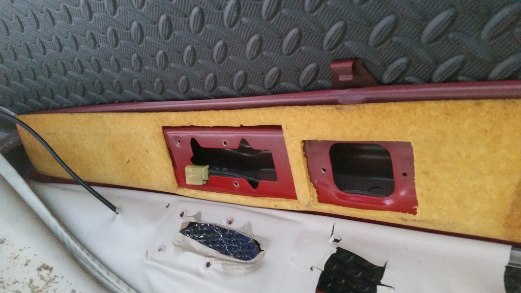
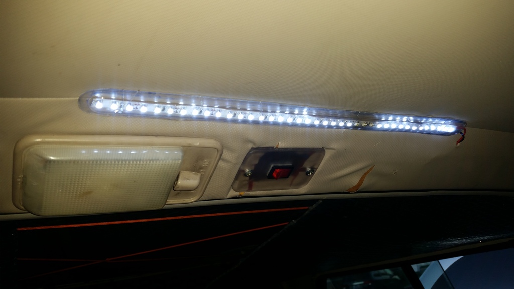
Even an LED dome light bulb replacement is anemic and I happen to have an extra LED array so:
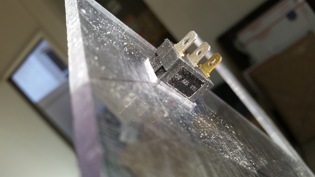
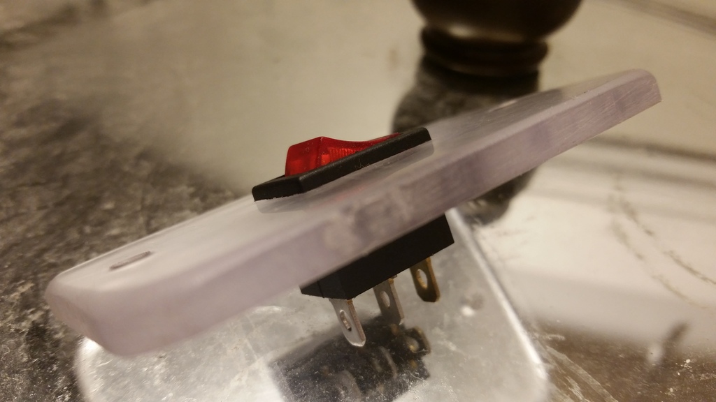
Made switch plate out of polycarbonate...
Made opening on right for the switch plate (on left is location of stock dome light):
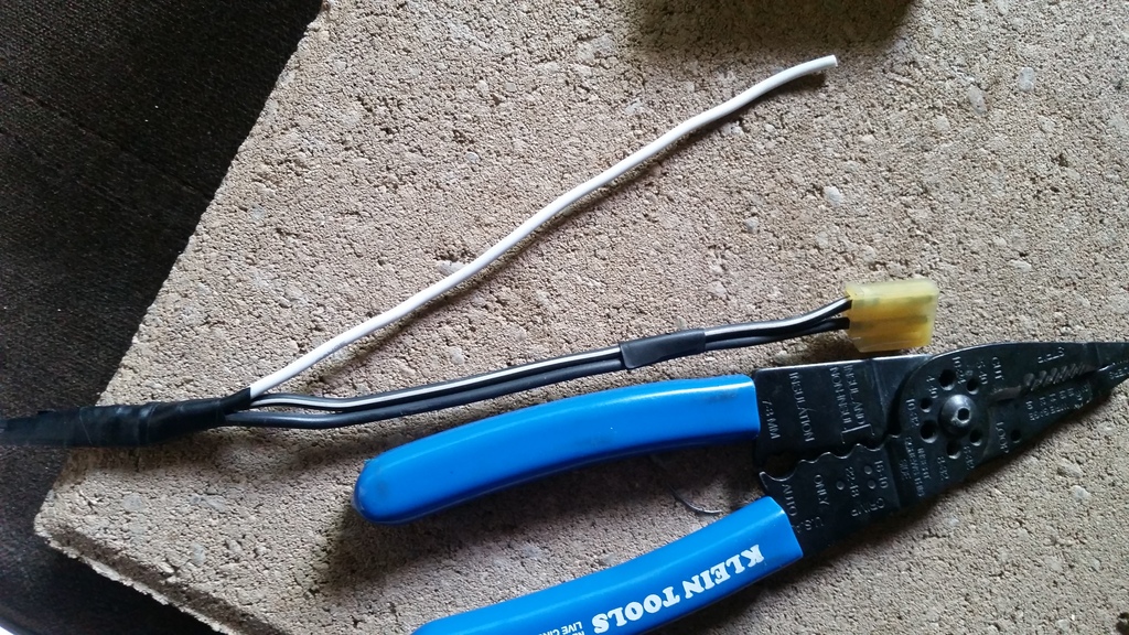
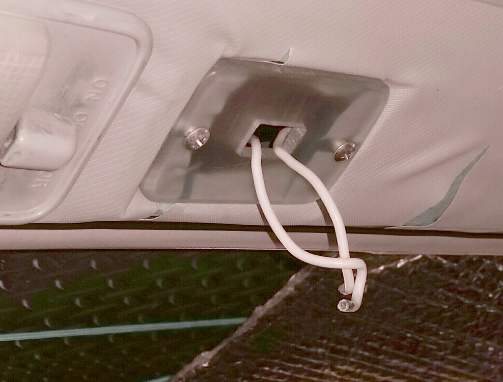
Tapped off the constant 12V line of the stock dome light wiring (black with white stripe):
I had to pull stock wiring out of its run to facilitate splicing/soldering. (Ignore the red wire. I just used it as fish-tape.)
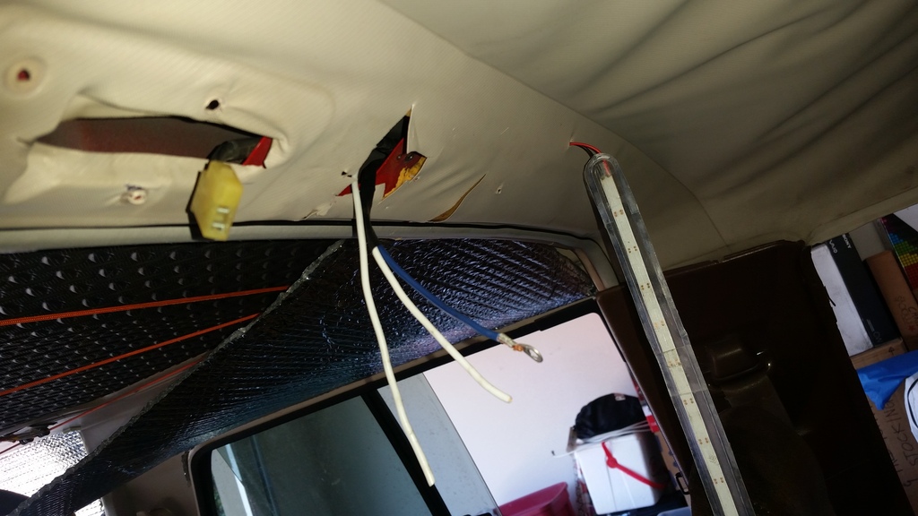
Ran wires back. Blue wire would be screwed into body ground and connected to negative side of LED array.
Switch plate installed. One white wire is tapped off from constant 12V. The other goes to positive side of LED array.
Stock dome light was reconnected and re-installed.
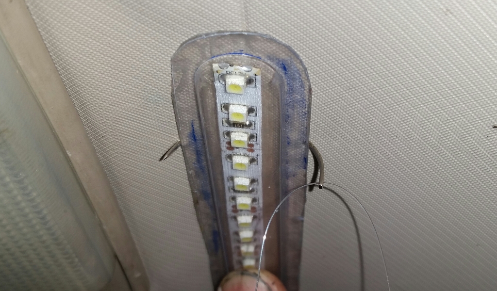
"Sewed" on the LED array with curved needle and fine nylon fishing line:
Yeah, there are some bad LED's on the array, and not very bright. The way I wired it, I can quickly replace it with a brighter array/bulb when I get it.
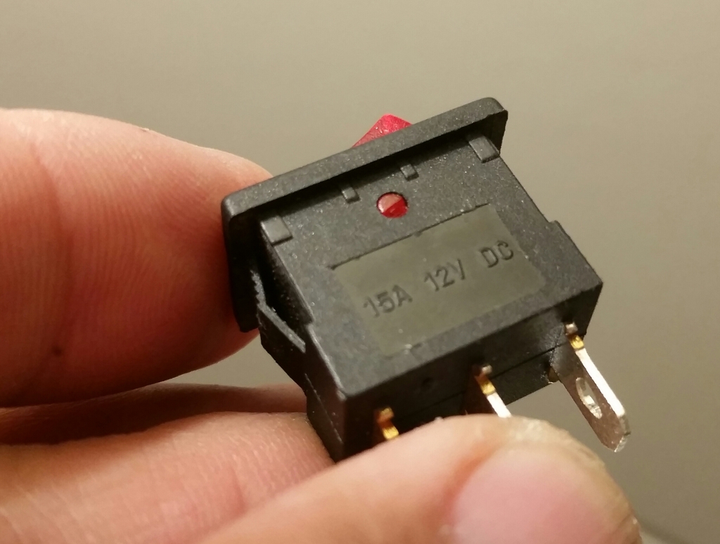
This is simply an on-off affair because I could not readily find a ON-Center OFF- ON rocker switch.
When I get the brighter bulb/array, stock dome light will be replaced with red LED for subtle lighting that will help preserve night vision.
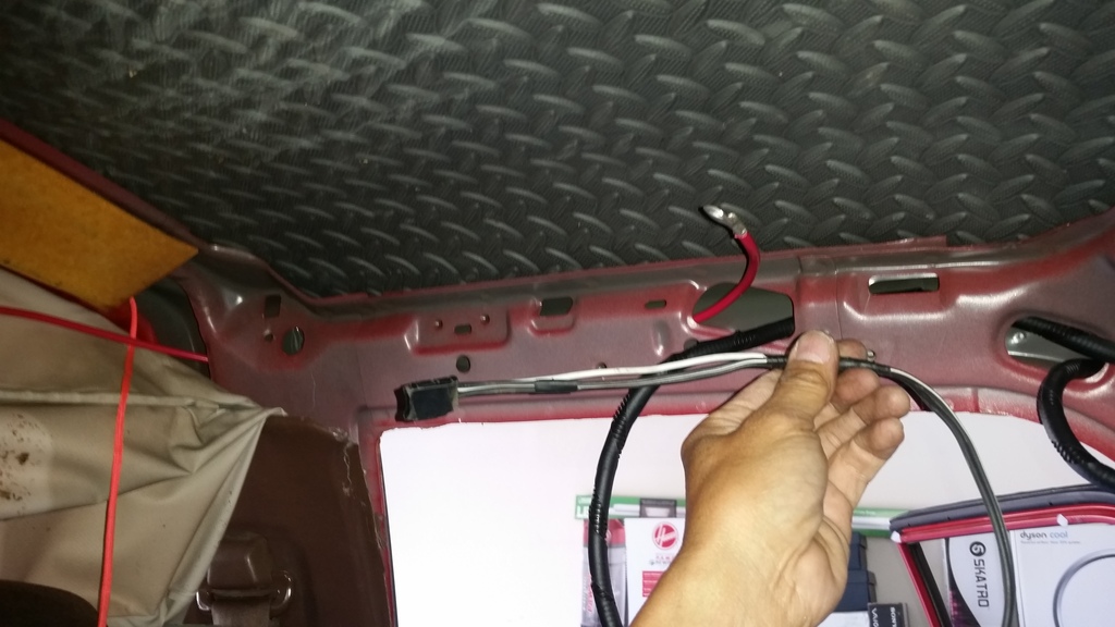
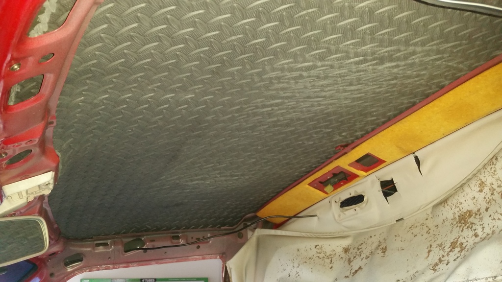
No, you are not looking at the floor I really replaced the crumbling, dusty, messy headliner insulation with "Best Step" diamond-plate pattern anti-fatigue mat like I did with headliner on my cap.
Like that on the Troopy @1:58 here:
When I get the time, I'll stick vibration dampener on roof, too.
Black cable above door runs to my hidden antenna sandwiched between fiberglas roof and topliner.
.Keywords: domelight, lefdomelight
.
.
Last edited by RAD4Runner; 04-28-2019 at 04:00 PM.
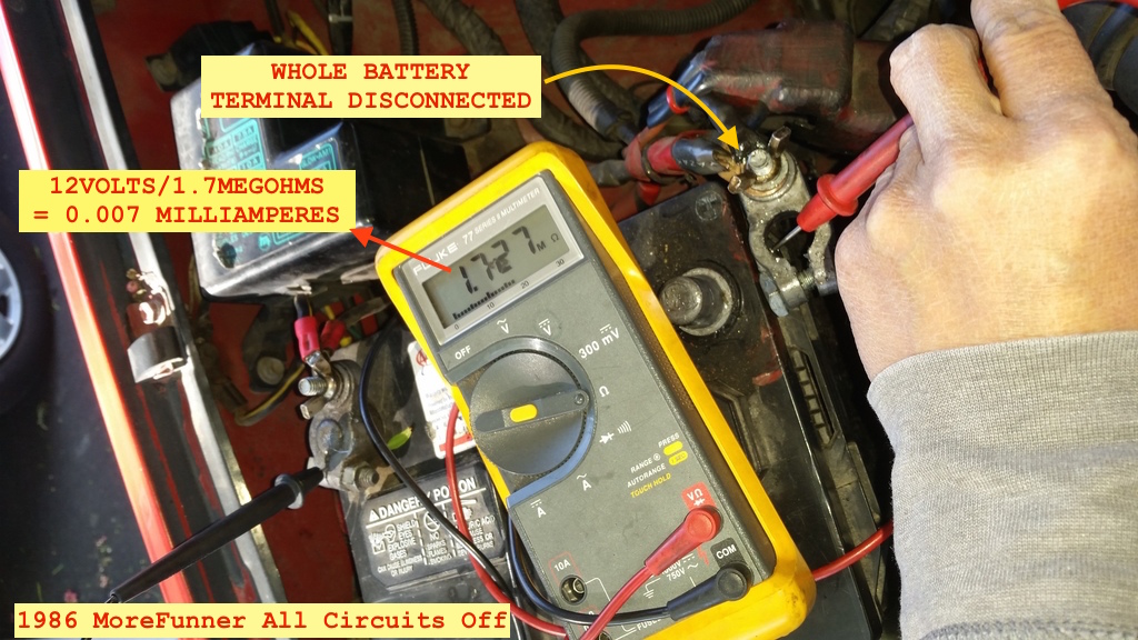
This is just to share how to use resistance measurement to troubleshoot for dead-short OR excessive current draw while Ignition switch is in OFF position:
Disconnect entire positive battery terminal. Ensure IGN sw is in OFF position, and all light switches are off. Multi-meter in resistance (ohm) mode. Begin in Megohm or higher range. Switch to lower range IF reading is lower than Meg-ohms. It would be best to have an assistant or to use alligator clips for your test probes.
Normal resistance should be in meg-ohm range. The 1.7Meg0hm reading below includes continuity through alternator windings / Rectifier.
If significantly lower (say, below 1k-ohms) resistance is seen with all systems off, take fuses off one at a time until you see one that significantly affect your reading.
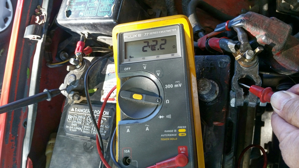
To demonstrate an example of a circuit causing current draw, I turned my LED Array deck light on:
Last edited by RAD4Runner; 11-18-2016 at 11:23 AM.
So I was a bit confused, did you put the urethane down, or did safelite do that for you?
Safelite tech removed old glass.
I cleaned pinchweld and "wall" down to bare metal,
Degreased using POR kit,
Applied metal treatment from POR kit.
Applied 3 coats of POR-15. Waited for each coat to get tacky before applying next coat.
Let cure for over 12 hours overnight and through morning (it cures with moisture).
I sanded it for texture, Safelite also scrubbed with scouring pad
I will prime and paint exposed POR-15 later.
Safelite tech re-installed in the afternoon.
I cleaned pinchweld and surrounding "wall". This video was taken before I further ground down the rust spot so that no loose (brown) rust was left but grey metal.
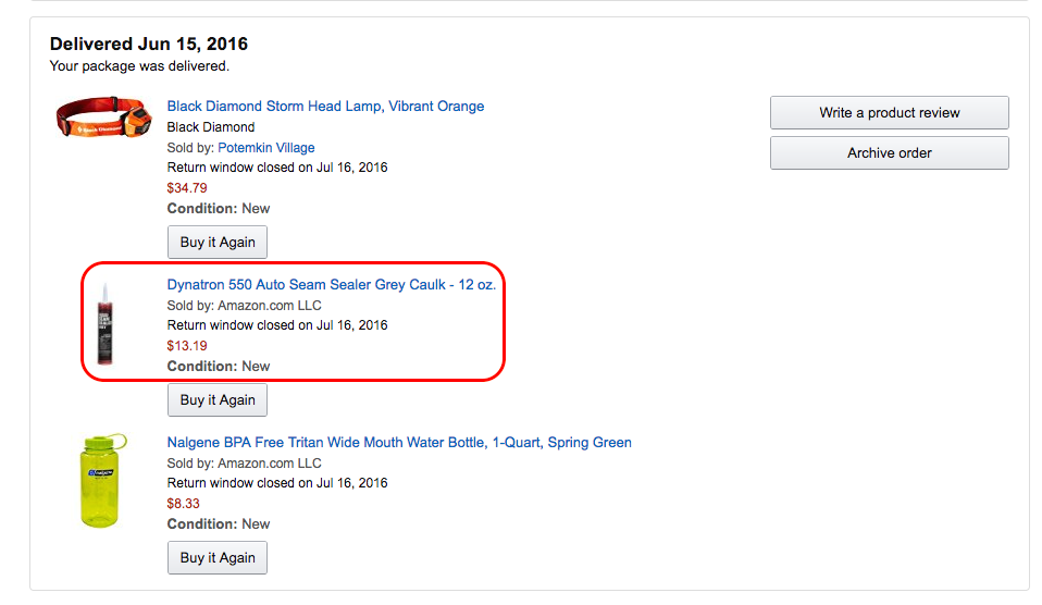
The guy that did mine used Dynatron 550 seam sealer, I still have a leak but he said it was the best seam sealer for these seams. mine leaks at about 6 inches over from the corner on top I saw on the passenger side. mine wasn't pitted like yours though. is that a small pinhole on that last pic on the pitted spot on the side or just the lighting? forgot to add you can see it come through the seam in that area as well thru the spread out area by the spot weld.
Last edited by Naked Runner; 11-26-2016 at 01:07 PM.
Reason: Forgot info
Your metal is in almost perfect shape, if that seam was the issue it would have been from the beginning... what did Toyota do from the factory that didn't cause issues?
As for fixing it, adding filler with a tig welder and grinding smooth maybe? Or POR Epoxy Putty? I've been considering this method here for some of the less messy but imperfect areas on my truck http://www.hotrod.com/articles/0306p...hannel-repair/
The guy that did mine used Dynatron 550 seam sealer,..
.. is that a small pinhole ...
Yes' that was a pinhole. I sealed it with DynaTRON as well.
Originally Posted by magnet18
what did Toyota do from the factory that didn't cause issues?
I think there was also sealer there, but came out when I cleaned the metal. I should have sealed it earlier with Dynapro555 which I also have. I'm wondering, though...
1) Would the same urethane adhesive used for the windshield work better than DynaTRON 555?
2) Would I get luckier with the Dynatron that Nakedrunner?
3) What surface would urethane or dynatron stick best on - POR-15 or clean, bare metal?
3) Any feedback from the bodywork experts?
Last edited by RAD4Runner; 12-03-2016 at 10:14 PM.
 10-22-2016, 09:53 PM