RAD4Runner's 1986 4Runner dlx Build-up
 09-19-2012, 10:19 AM
#41
Registered User
Thread Starter
Sound-Dampening / Sound-proofing Project
Moved details to Sound-proofing/Deadening Post
Last edited by RAD4Runner; 10-05-2012 at 11:53 PM. Reason: Moved details to sound-proofing-deadening post
 09-19-2012, 09:24 PM
#42
Registered User
Thread Starter
Click-Only Cranking Issue Caused By Toyota Electrical Engineering Blunder Fixed
Even after I cleaned my starter relay contacts, and after months of being able to start with no issues, the "C.O.R. Click-only" problem struck again. I reviewed the schematic and found the electrical engineering blunder explained here.
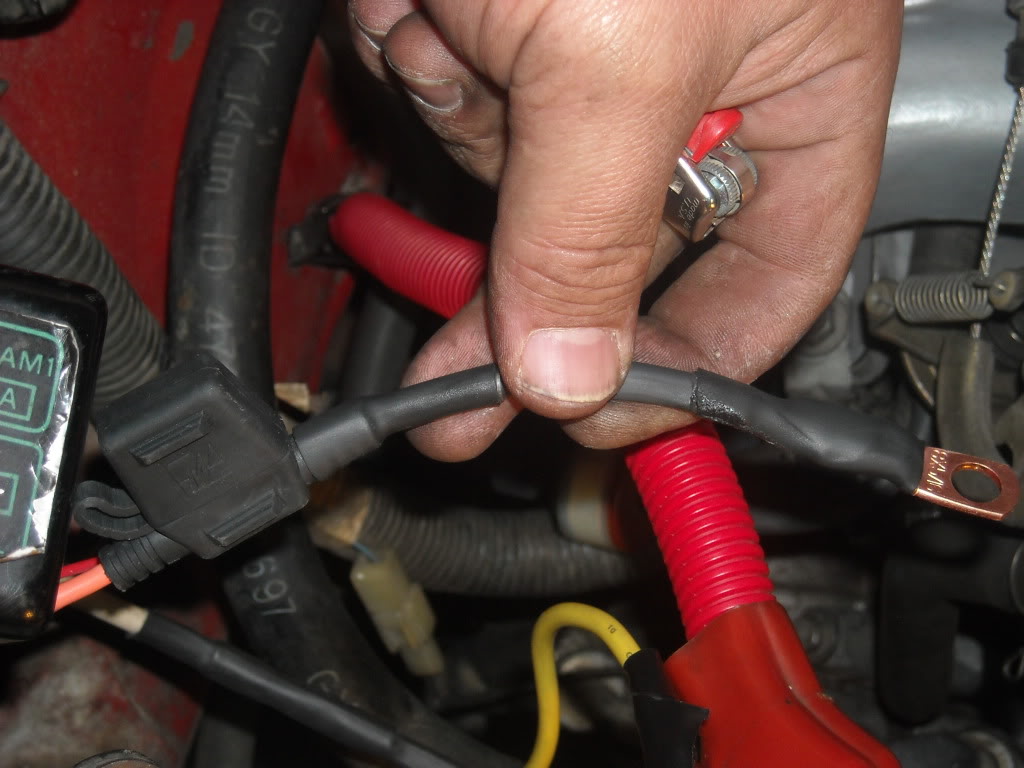
Below is the clean and robust fix for the starting (cranking) circuit wiring flaw. No additional or replacement parts, except for wire and an optional kill switch.
AFFECTED MODELS:
May 1986 to 1988 4Runners and trucks with 22R-E
1989-1992 4Runner V6, and 1989-1990 Pickup V6 Thanks, DrCreosote, for sharing your schematic.
Would appreciate if members with different year-models could verify theirs as well.
NOT AFFECTED MODEL:
According to this schematic, the 1988 4Runner, V6 3VZ does not have the wiring error.
Trucks made before May 1986 may not have the starter relay so this does not apply.
1986-1988 trucks/4Runners with auto transmission do not have starter relay, either. Click-only problem may also occur on them.
Examples:
Those made earlier than May Like richiegrich's Feb, and KidV's do not have starter relay.
For these models, I highly recommend adding a properly-wired starter relay.
Schematic of flawed stock wiring below shows that:
To verify if your stock wiring needs this fix refer to this with notes on how circuit without flaw should work:
To Fix, connect Pin 4 of starter relay to a AWG 12 wire to a fuse directly connected to battery positive.
Materials cost: Approx $11


BEST TO PUT FUSE AS CLOSE TO THE BATTERY AS POSSIBLE.
UPDATES:
Terry fixed his here
Stanz related repair where he replaced the broken stock starter relay with a 40-Amp aftermarket one is here.
Another one fixed:
Below is the clean and robust fix for the starting (cranking) circuit wiring flaw. No additional or replacement parts, except for wire and an optional kill switch.
AFFECTED MODELS:
May 1986 to 1988 4Runners and trucks with 22R-E
1989-1992 4Runner V6, and 1989-1990 Pickup V6 Thanks, DrCreosote, for sharing your schematic.
Would appreciate if members with different year-models could verify theirs as well.
NOT AFFECTED MODEL:
According to this schematic, the 1988 4Runner, V6 3VZ does not have the wiring error.
Trucks made before May 1986 may not have the starter relay so this does not apply.
1986-1988 trucks/4Runners with auto transmission do not have starter relay, either. Click-only problem may also occur on them.
Examples:
Those made earlier than May Like richiegrich's Feb, and KidV's do not have starter relay.
For these models, I highly recommend adding a properly-wired starter relay.
Schematic of flawed stock wiring below shows that:
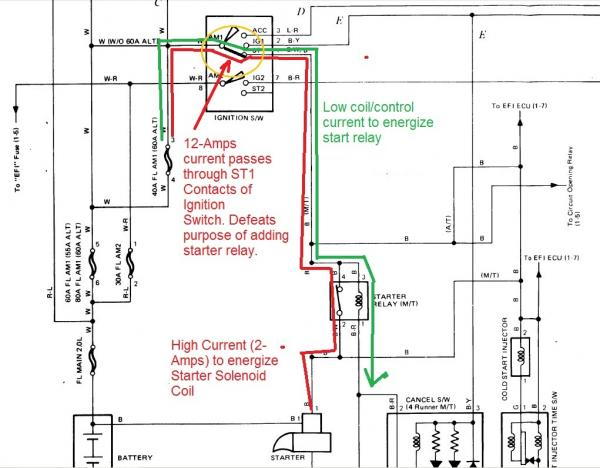
- High current (12-Amps) to energize starter solenoid passes through ST1 contacts of ignition switch. This puts unnecessary stress on switch contacts, cause pitting, high resistance, too much voltage drop (solenoid not getting enough voltage), and defeats purpose of adding the relay in the first place.
- Because solenoid contacts do not completely close, they will be arcing and/or heating up unnecessarily (like bad connection between power cord plug for electric flatiron makes plug and wire hot), hastening their demise.
To verify if your stock wiring needs this fix refer to this with notes on how circuit without flaw should work:
To Fix, connect Pin 4 of starter relay to a AWG 12 wire to a fuse directly connected to battery positive.
Materials cost: Approx $11
BEST TO PUT FUSE AS CLOSE TO THE BATTERY AS POSSIBLE.
UPDATES:
Terry fixed his here
Stanz related repair where he replaced the broken stock starter relay with a 40-Amp aftermarket one is here.
Another one fixed:
...Re-wired the starter relay(87 carbed 22r) last night per your post but to the 30amp... Ran that to the starter relay and it cranked great.
Success on Halloween. Just wanted to say thank you very much to the kind guys that helped me with my starter issue. Thank you rad4runner and chefyota4x4. It's been a busy past few days but I did get the circuit breaker and relay wired in on Halloween day and right when dark and trick or treaters were starting to come up I tried it and it works great. Thanks again guys for all your help! Bradley.
Last edited by RAD4Runner; 09-26-2019 at 04:24 PM. Reason: edited title for easy search
09-22-2012, 02:50 AM
#43
Registered User
iTrader: (1)

Join Date: Dec 2010
Location: Salt Lake City, UT
Posts: 314
Likes: 0
Received 0 Likes
on
0 Posts
I feel sorry for many of our fellow Yota owners who struggle with starting issues. Before wasting money and time unnecessarily replacing parts, it helps to understand how the system works.
I hope this simplified explanation could help with troubleshooting:

Poor (loose/corroded/pitted) contacts have high resistance. It is quite possible to have high resistance on ignition switch ST1 contacts, relay contacts, solenoid contacts, and wire connections, including ground straps. This will result in too much voltage drop across the contacts when there is current flowing through it.
Starter solenoid needs high current through its coil in order to actuate the plunger. Even if the individual components of the starting system seem to work/energize/click, there may be too much voltage drop across these components. Once you add up these voltage drops, you may end up with too little voltage (hence current) to energize the starter solenoid.
BIG BOO-BOO:
Note on schematic that starter solenoid control (coil) power is also taken from ignition switch ST1 contact, same contact that the start relay is supposed to relieve of the solenoid control current in the first place - DUH!
Pitting/corrosion of relay contacts will cause too much resistance across them, that altho relay clicks, you may not be getting full power though it.
A starter that works when smacked could mean:
I hope this simplified explanation could help with troubleshooting:
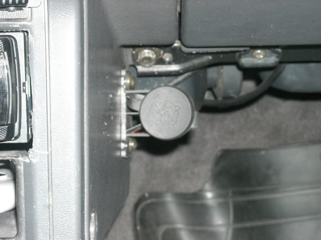
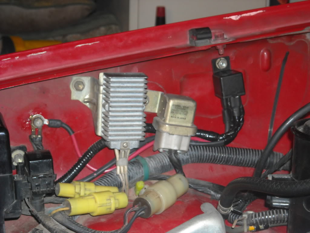
- Putting Ignition switch in "Start" position sends power (low current in green) to energize starter relay (located here). Have someone start the truck and listen to/feel the starter relay click. It also sends power to Circuit Opening Relay to start fuel pump, but that's a separate system. The COR is the relay that you hear click behind the glove compartment (barely visible here), when you try starting.
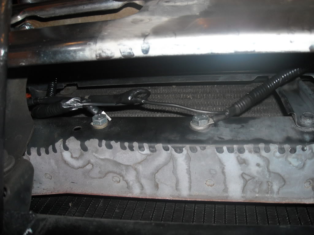
- Starter relay contacts close sending power (higher current, 12 Amperes on my 1986 4Runner orange) to starter solenoid though this connector, that plugs into starter solenoid here. (Starter solenoid piggy-backs on starter.)
Starter solenoid has larger coil than a relay because it has to pull in a plunger that closes heavier starter contacts to handle extremely large cranking current, and possibly actuate clutch to engage flywheel and starter gears (I'm not sure whether 4Runner starter has bendix drive or clutch)
- Starter solenoid contacts sends extremely high cranking current (in red in schematic) from heavy wire directly connected to the battery to starter to turn it.
Poor (loose/corroded/pitted) contacts have high resistance. It is quite possible to have high resistance on ignition switch ST1 contacts, relay contacts, solenoid contacts, and wire connections, including ground straps. This will result in too much voltage drop across the contacts when there is current flowing through it.
Starter solenoid needs high current through its coil in order to actuate the plunger. Even if the individual components of the starting system seem to work/energize/click, there may be too much voltage drop across these components. Once you add up these voltage drops, you may end up with too little voltage (hence current) to energize the starter solenoid.
BIG BOO-BOO:
Note on schematic that starter solenoid control (coil) power is also taken from ignition switch ST1 contact, same contact that the start relay is supposed to relieve of the solenoid control current in the first place - DUH!
Pitting/corrosion of relay contacts will cause too much resistance across them, that altho relay clicks, you may not be getting full power though it.
A starter that works when smacked could mean:
- Starter solenoid plunger mechanically hard to actuate and there is not enough current to move it, because of resistance in circuit. Smacking may get it unstuck.
- Plunger actuated and attempts to close contacts but because contacts are pitted/worn out it takes a little help to make them close all the way.
09-22-2012, 10:25 AM
#45
Registered User
Thread Starter
09-23-2012, 03:29 AM
#46
Super Moderator
Staff
iTrader: (1)
Join Date: Aug 2008
Location: Anderson Missouri
Posts: 11,788
Likes: 0
Received 21 Likes
on
19 Posts
You got the talent to really break down a schematic and make it understandable. I know what most parts of the schematic are, but dont really understand what is going on when in operation and that all made sense. Thanks.
Not in any rush, but could you do one on the COR. I understand that the Air Flow Meter kicks in the fuel pump and some how the Circuit Opening Relay has a part in it. I am not having any problems but that has been a mystery to me.
On any electrical problem, I just check resistance, see if it is getting power, and if the componet is operating, but that is about it and that usually works for me but to go thru a circuit like you just did, forget it, that is Greek to me, wish I could understand it a little better. The only thing I can figure out is what is happening on a light bulb.lol
09-24-2012, 10:47 AM
#48
Registered User
Thread Starter
You got the talent to really break down a schematic and make it understandable...
Not in any rush, but could you do one on the COR. I understand that the Air Flow Meter kicks in the fuel pump and some how the Circuit Opening Relay has a part in it. I am not having any problems but that has been a mystery to me.
...forget it, that is Greek to me...
Not in any rush, but could you do one on the COR. I understand that the Air Flow Meter kicks in the fuel pump and some how the Circuit Opening Relay has a part in it. I am not having any problems but that has been a mystery to me.
...forget it, that is Greek to me...
I have brief write-up on COR here. I'd like to add details but so busy at work.
I guess everyone has his forte. I also understand mechanical stuff but don't have equipment nor patience to work on them
 The cool thing with our first-gens is we can pretty much troubleshoot our trucks with our senses and a multi-meter (even a HF one - LOL!), so the stealerships or dishonest shops could not screw us, and we can actually help honest but not-very-competent shops solve our problems.
10-05-2012, 11:26 PM
The cool thing with our first-gens is we can pretty much troubleshoot our trucks with our senses and a multi-meter (even a HF one - LOL!), so the stealerships or dishonest shops could not screw us, and we can actually help honest but not-very-competent shops solve our problems.
10-05-2012, 11:26 PM
#49
Registered User
Thread Starter
Control For Rear Window From Rear Deck
This mod will allow one to roll rear window down from inside the rear deck (i.e., when camping in truck), without having to scramble over to front, put key in ignition in order to lower window from console switch. This will not cover how limit switches work.
Rear Window/Wiper Relay is behind panel near driver side seatbealt mechanism here:

Relevant wiring runs behind panel near left side of rollbar here:

Top Off Switch is also there.
Connector for Rear Window & Wiper Relay here:

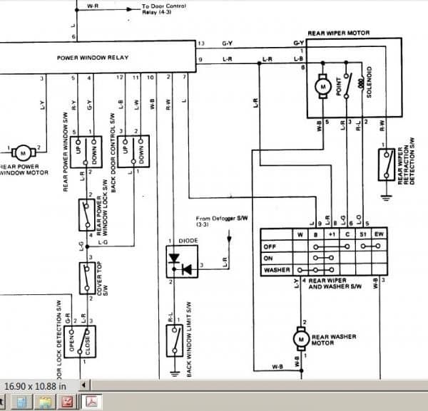
Up-Down pins to use so you would not need ignition to be on are pins 11 & 12
Check against schematic here:
Pin Numbering here:

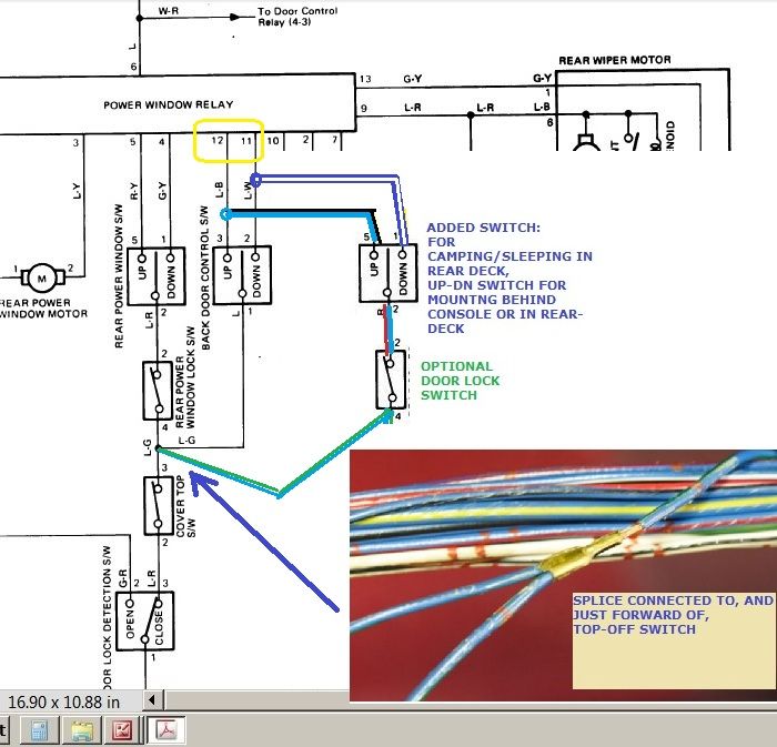
This mod will duplicate exactly what the key switch does:
Mod Schematic is here:
How backdoor window control switch (aka key switch) works:
Wire to pin 11 (light blue-white stripe) when connected to ground (via terminal 3 of top-off switch) will lower window.
Wire to pin 12 (lt blue-blk stripe) when connected to ground (via terminal 3 of top-off switch) will raise window.
(To test relay function, touching directly to chassis ground will work regardless of state of top off switch)
Wire a momentary SPDT with center-off switch (Up/Down) exactly same and in parallel with backdoor control switch (key switch),
I recommend to add fail-safe feature by inserting SPST window lock switch between center terminal of Up/Down switch and terminal 3 of top off switch. (i.e., cargo un-intentionally presses against any of the switches.)
You can do this by carefully stripping off insulation on wires above, and tapping into them. As you can see in pic below, I have labeled Light blue wire with white stripe "DN". Near label, Lt Blue Wire with Black stripe had been stripped to accept tap for "UP" wire.

Good place to connect center terminal of SPDT (Up/Down) switch is on this crimp, just forward of top off switch:

Console switch Operation:
In same manner, touching wire going to pin 4 (Green with yel stripe) will lower window, and Pin5 to ground (Red yellow stripe) will raise it. This is where console switch connects. Connecting directly to ground bypasses console rear window lock and rear door lock detection switches.
So... here it is in action:
Rear Window/Wiper Relay is behind panel near driver side seatbealt mechanism here:
Relevant wiring runs behind panel near left side of rollbar here:
Top Off Switch is also there.
Connector for Rear Window & Wiper Relay here:
Up-Down pins to use so you would not need ignition to be on are pins 11 & 12
Check against schematic here:
Pin Numbering here:
This mod will duplicate exactly what the key switch does:
Mod Schematic is here:
How backdoor window control switch (aka key switch) works:
Wire to pin 11 (light blue-white stripe) when connected to ground (via terminal 3 of top-off switch) will lower window.
Wire to pin 12 (lt blue-blk stripe) when connected to ground (via terminal 3 of top-off switch) will raise window.
(To test relay function, touching directly to chassis ground will work regardless of state of top off switch)
Wire a momentary SPDT with center-off switch (Up/Down) exactly same and in parallel with backdoor control switch (key switch),
I recommend to add fail-safe feature by inserting SPST window lock switch between center terminal of Up/Down switch and terminal 3 of top off switch. (i.e., cargo un-intentionally presses against any of the switches.)
You can do this by carefully stripping off insulation on wires above, and tapping into them. As you can see in pic below, I have labeled Light blue wire with white stripe "DN". Near label, Lt Blue Wire with Black stripe had been stripped to accept tap for "UP" wire.
Good place to connect center terminal of SPDT (Up/Down) switch is on this crimp, just forward of top off switch:
Console switch Operation:
In same manner, touching wire going to pin 4 (Green with yel stripe) will lower window, and Pin5 to ground (Red yellow stripe) will raise it. This is where console switch connects. Connecting directly to ground bypasses console rear window lock and rear door lock detection switches.
So... here it is in action:
Last edited by RAD4Runner; 01-05-2016 at 02:58 PM. Reason: Added Schematic
10-06-2012, 09:48 AM
#50
Hey there, Mang!  ...... Just thought I'd comment after reading your last choice of mods(UPGRADES, IMHO!!!
  ) ....... YEAAAAAAAAAAAAAAAAAAAAA! hahahaha.
Seriously. RAD? you're RAD! I'm so stoked you've dug in to this!!! I probably should have just tried this a while back...(I have the Manual Page Scanned to my Computer.... Just been putting it and couple other things off for 50% Off at PYPart Sales! ... Now, heck, I'll just COPY YOUR PAGE! hehe)
It's funny... the second you started talking without pictures/diagrams.... POOF, my proverbial CRANIAL CABBAGE factor kicked in! lol.
lol.
I believe you're in The Great White North, or PNW, right? Maybe it was Colorado... ....dangit, I hate getting old! hahaha.(Jk, I actually retain quite a bit compared to many 20 somethings I know
  ).... I ask on your location because I thought I might have an extra 3-4 SWITCHES, lol... In case you needed one! (LEAST I can do since you're doing all the HARD work here FOR me, right?) .... BUT, of course, I'm sure you're prepared and don't need one, right? (Lemme know, k?)
"SAFETY".... HAAAAAAAAAAAAA! I mean....... I thought about this for DAYZ, after my wreck..... I had multiple fractures, punctured lung, skull crack... BUT, if I hadn't, or if I HAD TO TRY to get out from the middle or something.... GOOD LUCK! NO WAY, either, for back seat passengers to get out the back should they be blocked by the front peoples who might be seriously injured/pinned/or worse ).... I GET IT, I understand why it's important to have the key on and top on..... Nothing like a giant thick window rolling up at 80MPH in a strong head wind on the 395Hwy and POWWWWWWWWW, .... suddenly, you're "Darkman!"
  BUT, for camping? YESSSSS!
Interested to see what you do about the switch in back not being depressed by gear, etc.
WHAT IN THE HECK IS "SPST"??? I wanna guess........ Single Poll Switch Terminal....... Oh forget it, just tell me. lol. I understand.... I THINK, lol... You mean something to interrupt the "constant hot" to the switch in the back, right?(So it can't be tripped by anything?) ... Sorry, I know you said that, basically... just was thrown by the 'foreign-to-me-Acronym', hehehe.
SOOOOOOOOOOOOOOOOOOOOOOOO LIKE TOTALLY BOOKMARKED, DUDE! ..... But really;


 .......... Thanks for the lift! >>>
PS> So, ...the smaller relay in the panel there, looks like one of the main relays in the kick panel... that one... THAT is the rear window wiper motor relay? (I know that the window can't go down if the wiper is NOT COMPLETELY up to the point that the metal is contacting the base(completed contact circuit ground thingymadoer, right?).....
PSS> I need to tap into the "safety lock" THINGY so I can put a dome light in the wiper cover... Guess I need to wire the 2 deck lamps I'll have to it as well... and maybe like 4crawler, back up to the "Deck Lamp Switch".... Just wondering if you could make a couple pictures of where to wire in for that mod?
...... Just thought I'd comment after reading your last choice of mods(UPGRADES, IMHO!!! ) ....... YEAAAAAAAAAAAAAAAAAAAAA! hahahaha. Seriously. RAD? you're RAD! I'm so stoked you've dug in to this!!! I probably should have just tried this a while back...(I have the Manual Page Scanned to my Computer.... Just been putting it and couple other things off for 50% Off at PYPart Sales! ... Now, heck, I'll just COPY YOUR PAGE!
hehe)It's funny... the second you started talking without pictures/diagrams.... POOF, my proverbial CRANIAL CABBAGE factor kicked in!
lol. I believe you're in The Great White North, or PNW, right? Maybe it was Colorado...
....dangit, I hate getting old! hahaha.(Jk, I actually retain quite a bit compared to many 20 somethings I know ).... I ask on your location because I thought I might have an extra 3-4 SWITCHES, lol... In case you needed one! (LEAST I can do since you're doing all the HARD work here FOR me, right?) .... BUT, of course, I'm sure you're prepared and don't need one, right? (Lemme know, k?) "SAFETY".... HAAAAAAAAAAAAA! I mean....... I thought about this for DAYZ, after my wreck..... I had multiple fractures, punctured lung, skull crack... BUT, if I hadn't, or if I HAD TO TRY to get out from the middle or something.... GOOD LUCK! NO WAY, either, for back seat passengers to get out the back should they be blocked by the front peoples who might be seriously injured/pinned/or worse
).... I GET IT, I understand why it's important to have the key on and top on..... Nothing like a giant thick window rolling up at 80MPH in a strong head wind on the 395Hwy and POWWWWWWWWW, .... suddenly, you're "Darkman!" BUT, for camping? YESSSSS! Interested to see what you do about the switch in back not being depressed by gear, etc.
WHAT IN THE HECK IS "SPST"??? I wanna guess........ Single Poll Switch Terminal....... Oh forget it, just tell me. lol. I understand.... I THINK, lol... You mean something to interrupt the "constant hot" to the switch in the back, right?(So it can't be tripped by anything?) ... Sorry, I know you said that, basically... just was thrown by the 'foreign-to-me-Acronym', hehehe.
SOOOOOOOOOOOOOOOOOOOOOOOO LIKE TOTALLY BOOKMARKED, DUDE!
..... But really; .......... Thanks for the lift! >>> PS> So, ...the smaller relay in the panel there, looks like one of the main relays in the kick panel... that one... THAT is the rear window wiper motor relay? (I know that the window can't go down if the wiper is NOT COMPLETELY up to the point that the metal is contacting the base(completed contact circuit ground thingymadoer, right?).....
PSS> I need to tap into the "safety lock" THINGY so I can put a dome light in the wiper cover... Guess I need to wire the 2 deck lamps I'll have to it as well... and maybe like 4crawler, back up to the "Deck Lamp Switch".... Just wondering if you could make a couple pictures of where to wire in for that mod?
10-06-2012, 04:13 PM
#51
Registered User
Thread Starter
Seriously. RAD? you're RAD! I'm so stoked you've dug in to this!!! I probably should have just tried this a while back...(I have the Manual Page Scanned to my Computer.... Just been putting it and couple other things off for 50% Off at PYPart Sales! ... Now, heck, I'll just COPY YOUR PAGE! hehe)
hehe)You should just download the pdf of FSM (on our sigs). More convenient.
Interested to see what you do about the switch in back not being depressed by gear, etc.
WHAT IN THE HECK IS "SPST"???...Oh forget it, just tell me. lol. momentary, center-off
Perfect example is the console Up/Down switchSingle-pole = completes only one circuit/line at a time
Double-throw = switches from one line to the other
Momentary = only completes a circuit while you press on it
Center-off = center terminal disconnects from both circuits when released
Good reference on wikipedia
You mean something to interrupt the "constant hot" to the switch in the back, right?(So it can't be tripped by anything?)
the smaller relay in the panel there, looks like one of the main relays in the kick panel... that one... THAT is the rear window wiper motor relay?
I need to tap into the "safety lock" THINGY so I can put a dome light in the wiper cover... Guess I need to wire the 2 deck lamps I'll have to it as well... and maybe like 4crawler, back up to the "Deck Lamp Switch".... Just wondering if you could make a couple pictures of where to wire in for that mod?
10-07-2012, 01:02 AM
#52
Wow, awesome answers, man! hahaha.. Now just come over and do it for me, will ya? ...... Just messin.
I'll get back on this stuff you answered.. Gotta crash. BUT, Yeah, I have an FSM link in my sig too, lol.... I have the 88 loaded to my computer... SOME things are slightly different, like injectors and such... but general chassis and body electrical is mostly the same. I'll dig into it further... I just have always had trouble reading on electrical stuff... I apply it once I get it just fine, like the Off road lights, wiring in the AMP professional quality, Aux Fuse Block..... Just GETTING there at times, like when I have to hack into stuff in a spaghetti soup of wiring... Something in my brain goes 'twoingggggink'! lol.
Thanks again, RAD
...... Just messin. I'll get back on this stuff you answered.. Gotta crash. BUT, Yeah, I have an FSM link in my sig too, lol.... I have the 88 loaded to my computer... SOME things are slightly different, like injectors and such... but general chassis and body electrical is mostly the same. I'll dig into it further... I just have always had trouble reading on electrical stuff... I apply it once I get it just fine, like the Off road lights, wiring in the AMP professional quality, Aux Fuse Block..... Just GETTING there at times, like when I have to hack into stuff in a spaghetti soup of wiring... Something in my brain goes 'twoingggggink'! lol.
Thanks again, RAD
10-08-2012, 02:56 AM
#53
Hey RAD, ....
Gonna try to wire in the lights, first... But wondered if it would be best to do it all at once? ......... Dome Light in back, bypass the Deck Lamp and wire it always hot(same with the dome) and Window Relay thingymadoer......... .... I'm JUST NOW heading to bed... So I'm just IN NO WAY prepared, til tomorrow, to read electronic schematics or even LOOK AT WIRES! ..... But I looked anyway! haha. Still pretty lost on a couple things....
Back to the drawing/learning board tomorrow...
Thanks again for all you've posted up man... it's got me much closer to figuring this all all.
Gonna try to wire in the lights, first... But wondered if it would be best to do it all at once? ......... Dome Light in back, bypass the Deck Lamp and wire it always hot(same with the dome) and Window Relay thingymadoer.........
.... I'm JUST NOW heading to bed... So I'm just IN NO WAY prepared, til tomorrow, to read electronic schematics or even LOOK AT WIRES! ..... But I looked anyway! haha. Still pretty lost on a couple things.... Back to the drawing/learning board tomorrow...
Thanks again for all you've posted up man... it's got me much closer to figuring this all all.
10-08-2012, 09:19 AM
#54
Registered User
Thread Starter
Do them all at once.
Morning, Chef!
LOL! NP, if we can find a free weekend. Work and life are crazy busy.
Yep best to do once, because they're all behind same 2 panels and need to undo the harness that runs along driver's side threshold. If you want to turn existing deck lamp into a low - light (I used brighter LED array for the overhead one), you might want to make it independent of the tail lights; Need to re-wire behind driver-side kick panel fuse block for that. Terry describes how to un-mount that fuse block from wall on his post.
Tip,
If you want connector for when top goes off cut-off the seatbelt buckle switch (here) and reuse it.
Oh yeah, to help make in-deck door switches cargo proof, mount them to left of forward roll-bar verticals. That's what I plan to do with mine.
I would do directly wired (bright one) deck lamp, but I do not have fuse box for it. Want:
- Separate a fuse boxes for interior lights yet and and auxiliary lights, and
- Fuses to be as close to battery as possible so would appreciate leads on weather-resistant and heat-resistant fuse box.
10-08-2012, 11:11 AM
#55
Look RAD, if you are going to keep speaking Cantonese to me.... at least put pictures! hahahaha... JK, .... TOTALLY kidding. THANKS! I almost get this now....
and, .... I installed this a few months ago... This what you're talking about? >>>
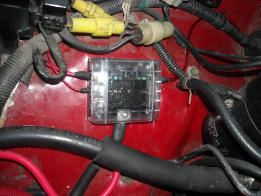
I should have installed more of these... BUT, I will be installing them in the tailgate area and even one on the Bumper(These are waterproof.... IF YOU WIRE THEM RIGHT! lol) This is wired directly to the Aux. Marine Fuse Block, too... >.....
This is Wired there too>>>
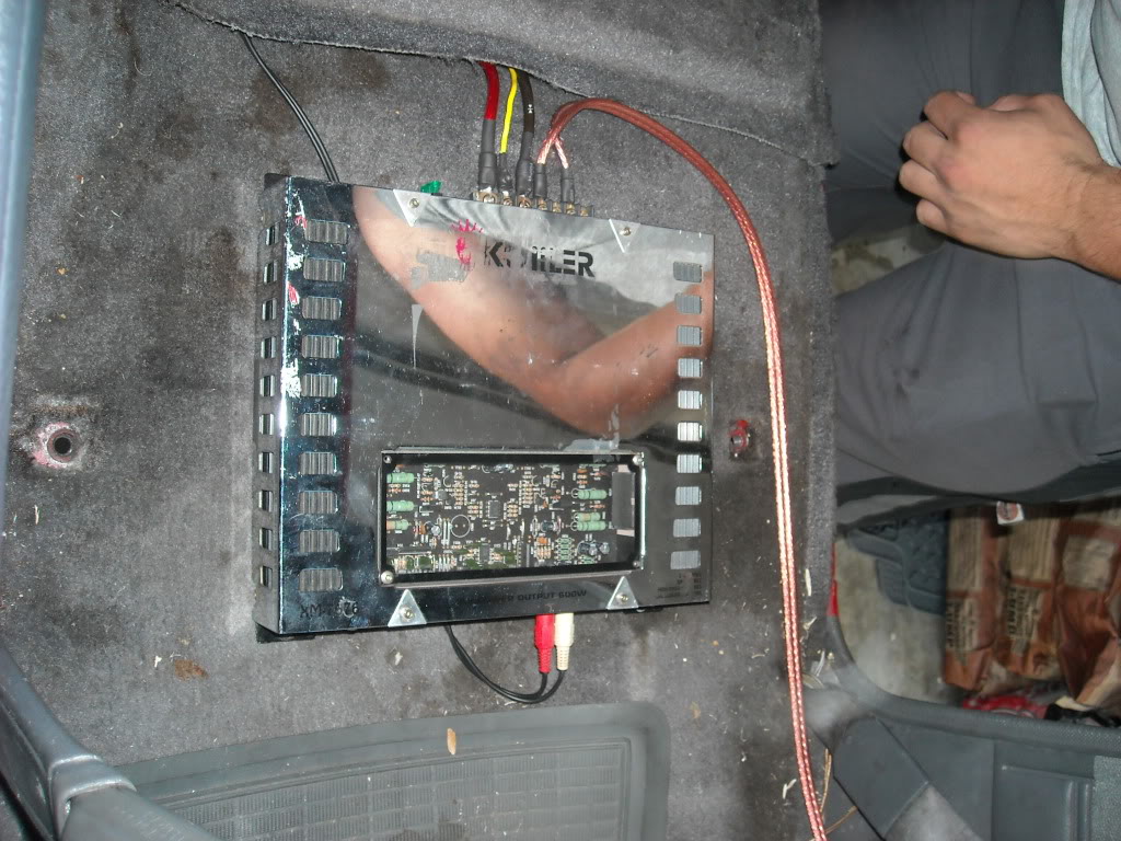
My lights are wired to it as well(Through this relay)..........
8" Dick Cepek Lights....
Wired them up as solid as I could.......
Got switched power here......
Got switched power to the SWITCH, lol....
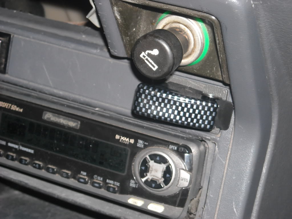
Switch in...
Voila, it was done, lol. At first, I didn't have the Marine Fuse Block.... I wired it with one of these to hot........
And YES, I use heat shrink on everything! hahaha.
Running 4AWG to the Fuse block.... Guess I could run '0'AWG .... But it's fine for what I'm running.
I might switch to a 12 Post Terminal, eventually, cuz it's gonna run out of posts quick! hahaha.
and, .... I installed this a few months ago... This what you're talking about? >>>
I should have installed more of these... BUT, I will be installing them in the tailgate area and even one on the Bumper(These are waterproof.... IF YOU WIRE THEM RIGHT! lol) This is wired directly to the Aux. Marine Fuse Block, too... >.....
This is Wired there too>>>
My lights are wired to it as well(Through this relay)..........
8" Dick Cepek Lights....
Wired them up as solid as I could.......
Got switched power here......
Got switched power to the SWITCH, lol....
Switch in...
Voila, it was done, lol. At first, I didn't have the Marine Fuse Block.... I wired it with one of these to hot........
And YES, I use heat shrink on everything! hahaha.
Running 4AWG to the Fuse block.... Guess I could run '0'AWG .... But it's fine for what I'm running.
I might switch to a 12 Post Terminal, eventually, cuz it's gonna run out of posts quick! hahaha.
10-12-2012, 09:57 AM
#56
Registered User

Join Date: Jan 2012
Location: New Mexico
Posts: 193
Likes: 0
Received 0 Likes
on
0 Posts
Starting Circuit FIX Question
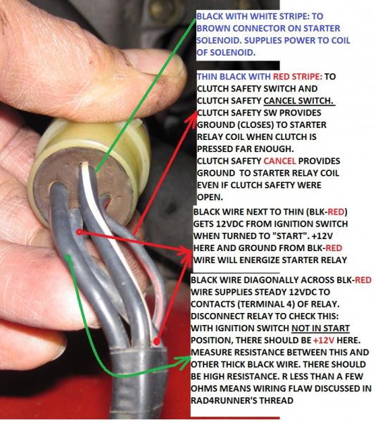
So I am having a lot of these start troubles. Check the resistance between to the two black wires on the starter relay. Not very good.
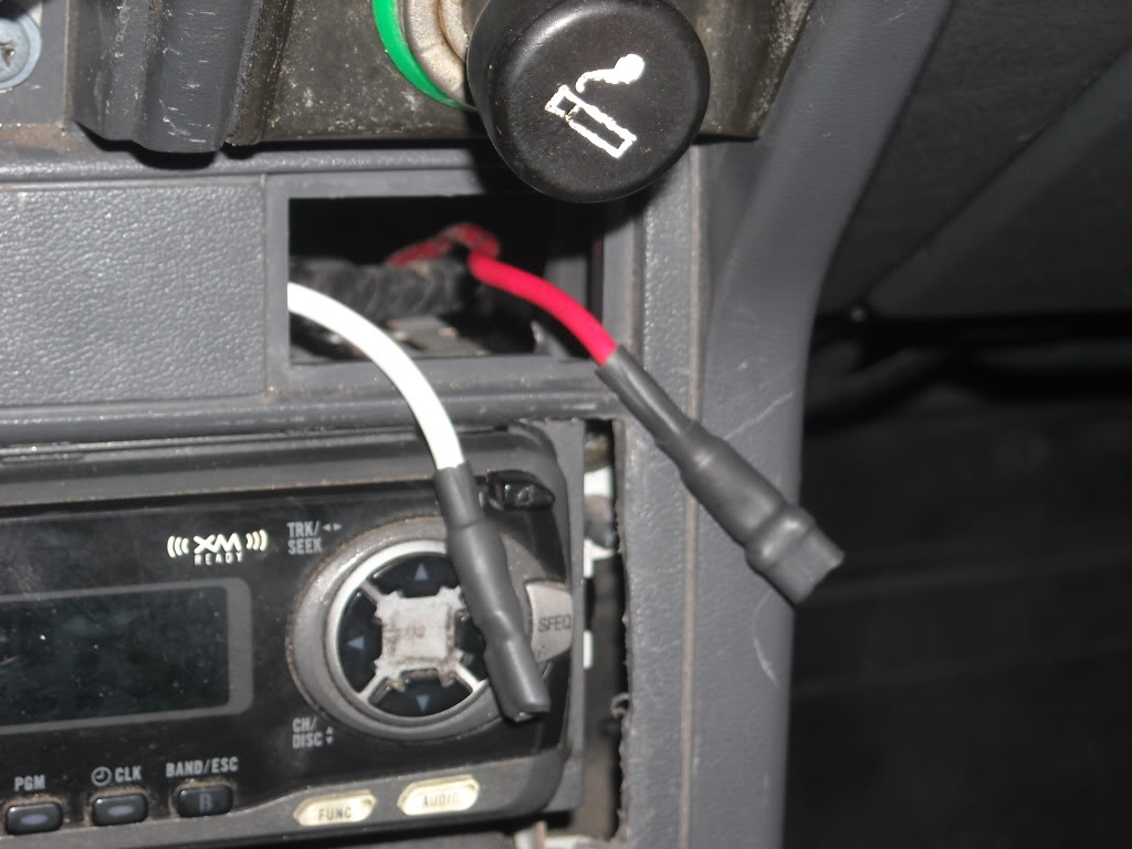
I cut the black wire at #4 and I was going to connect it up to the white from the 40A fuse like in the diagrams.
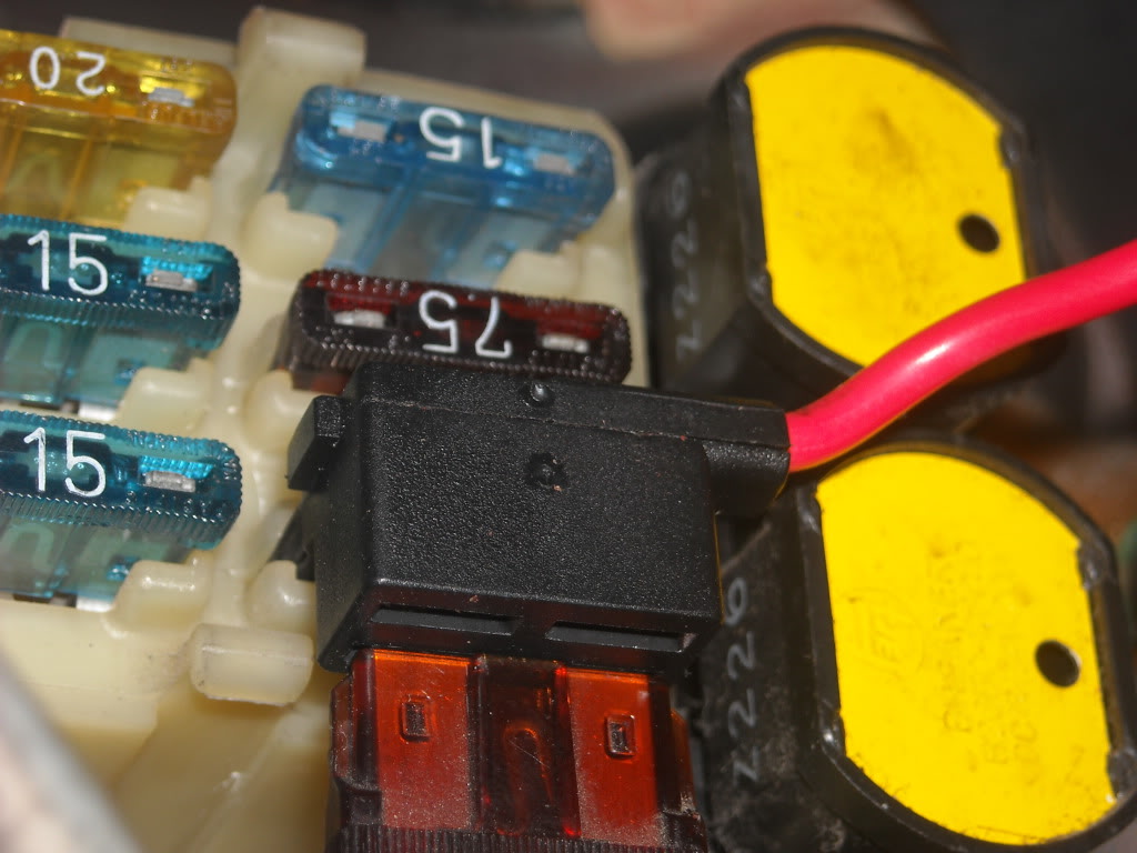
So my big question is: Where is that white wire?
I popped off the top to the fuse box and I can see a single white wire going in but I don't think that is the right one.
Thanks for the diagrams and any help.
ara
So I am having a lot of these start troubles. Check the resistance between to the two black wires on the starter relay. Not very good.
I cut the black wire at #4 and I was going to connect it up to the white from the 40A fuse like in the diagrams.
So my big question is: Where is that white wire?
I popped off the top to the fuse box and I can see a single white wire going in but I don't think that is the right one.
Thanks for the diagrams and any help.
ara
10-12-2012, 12:27 PM
#57
Registered User
Thread Starter
Did you disconnect the relay before measuring resistance? (to get reliable readings and avoid confusion)
Was ignition switch NOT in start position when you measured? (to get reliable readings and avoid confusion)
On circuit with proper wiring there should be high resistance between those two black wires. Low resistance (around 1 ohm) confirms that circuit is wired improperly as described in "Wiring Flaw" post
I cut the black wire at #4 and I was going to connect it up to the white from the 40A fuse like in the diagrams. So my big question is: Where is that white wire?
I popped off the top to the fuse box and I can see a single white wire going in but I don't think that is the right one.
I popped off the top to the fuse box and I can see a single white wire going in but I don't think that is the right one.
10-13-2012, 06:14 AM
#59
Registered User
Join Date: Jan 2012
Location: New Mexico
Posts: 193
Likes: 0
Received 0 Likes
on
0 Posts
Not very good means what resistance did you get?
Did you disconnect the relay before measuring resistance? (to get reliable readings and avoid confusion)
Was ignition switch NOT in start position when you measured? (to get reliable readings and avoid confusion)
On circuit with proper wiring there should be high resistance between those two black wires. Low resistance (around 1 ohm) confirms that circuit is wired improperly as described in "Wiring Flaw" post
Wind and rain kicked up so I didn't finish making the connection to the wire yesterday, going back in an hour or so.
Thanks for the photo showing where the wire is at!
ara
10-13-2012, 12:07 PM
#60
Registered User
Thread Starter
That's a Toyota Boo-boo. I wonder if Toyota has corrected it on other gens. Would owners of other gens please sound off? This would help a lot of fellow Yotetechies.


