
Need some help with 3.0 Gauge Senders for Oil & Water
 01-21-2010, 07:19 PM
#1
Registered User
Thread Starter

Join Date: Dec 2007
Posts: 22
Likes: 0
Received 0 Likes
on
0 Posts
Need some help with 3.0 Gauge Senders for Oil & Water
Subject basically says it all... I stupidly forgot to pull the water temp and oil pressure senders from the 3.0 from my 1991 Pickup before I sold the engine. I am putting a Benz diesel into it and I need to thread the senders into the new engine. The question is.. Where are they, and what color are the wires going to them? I need to find a 3.0 V6 manual in a junk yard for a couple other reasons so hopefully I can pull them then and at least figure out what the wires are in the very complicated engine harness...
Would anyone be willing to let me know -- possibly post pictures? I know there are several coolant temp sensors as well for the computer, etc..
thanks,
Andre
Would anyone be willing to let me know -- possibly post pictures? I know there are several coolant temp sensors as well for the computer, etc..
thanks,
Andre
 01-22-2010, 07:31 AM
#2
Registered User
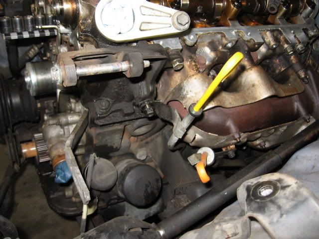
The oil pressure sender is the easy one.
It is on the driver's side front of the motor, right down by the oil filter. The wire going to it comes off of the wiring harness that drops off the front driver's side of the motor and then heads over to the driver's side fender well.
Picture of oil sender, the smaller round part to the left of the oil filter in this pic. You can see the pigtail from the sender hanging down.
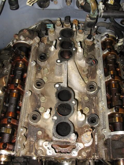
As for the temp sender, I can point you in the right direction, but I don't know which of the four sensors is the correct one on the sensor block. There is a sensor block on the back/top of the motor, down behind the plenum. There are four sensors and one thermal vacuum switch threaded into that block. Of the sensors, one has a single wire going to it and a spade connection, on the far driver's side. The two in the middle have two wires going to them. The one on the passenger's side has one wire with a plastic retention shroud. I never understood which one was the gauge for the dash gage.
Maybe someone else can point it out which sensor is the gage sending unit?
Sensor pictures:
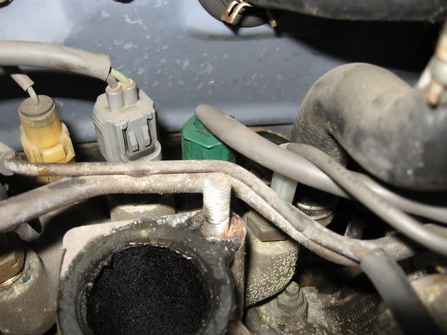
Close up of the sensors with wires, shows wire routing, two from the left, two from the right.
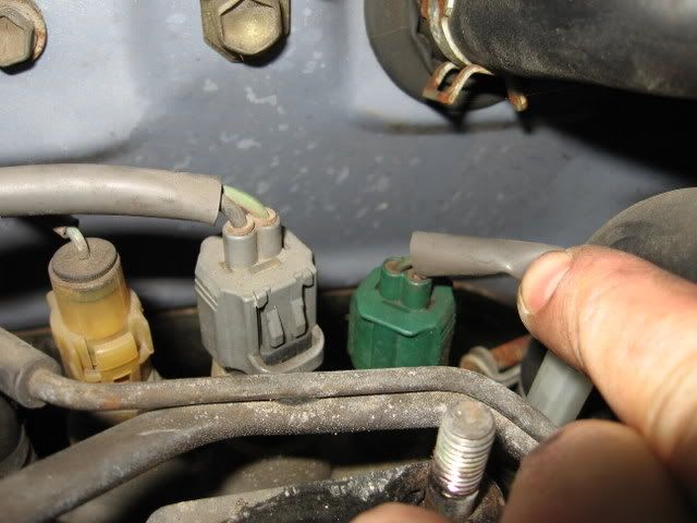
Close up on the sensors with wires (far right single wire partially hidden by my hand):
Top view with harness and injector rail removed from the motor:
It is on the driver's side front of the motor, right down by the oil filter. The wire going to it comes off of the wiring harness that drops off the front driver's side of the motor and then heads over to the driver's side fender well.
Picture of oil sender, the smaller round part to the left of the oil filter in this pic. You can see the pigtail from the sender hanging down.
As for the temp sender, I can point you in the right direction, but I don't know which of the four sensors is the correct one on the sensor block. There is a sensor block on the back/top of the motor, down behind the plenum. There are four sensors and one thermal vacuum switch threaded into that block. Of the sensors, one has a single wire going to it and a spade connection, on the far driver's side. The two in the middle have two wires going to them. The one on the passenger's side has one wire with a plastic retention shroud. I never understood which one was the gauge for the dash gage.
Maybe someone else can point it out which sensor is the gage sending unit?
Sensor pictures:
Close up of the sensors with wires, shows wire routing, two from the left, two from the right.
Close up on the sensors with wires (far right single wire partially hidden by my hand):
Top view with harness and injector rail removed from the motor:
Last edited by OutlawMike; 01-22-2010 at 07:32 AM.
01-22-2010, 08:07 AM
#3
Registered User
Join Date: Jul 2008
Location: GA
Posts: 1,062
Likes: 0
Received 0 Likes
on
0 Posts
The oil pressure sender is the easy one.
It is on the driver's side front of the motor, right down by the oil filter. The wire going to it comes off of the wiring harness that drops off the front driver's side of the motor and then heads over to the driver's side fender well.
Picture of oil sender, the smaller round part to the left of the oil filter in this pic. You can see the pigtail from the sender hanging down.
As for the temp sender, I can point you in the right direction, but I don't know which of the four sensors is the correct one on the sensor block. There is a sensor block on the back/top of the motor, down behind the plenum. There are four sensors and one thermal vacuum switch threaded into that block. Of the sensors, one has a single wire going to it and a spade connection, on the far driver's side. The two in the middle have two wires going to them. The one on the passenger's side has one wire with a plastic retention shroud. I never understood which one was the gauge for the dash gage.
Maybe someone else can point it out which sensor is the gage sending unit?
Sensor pictures:
Close up of the sensors with wires, shows wire routing, two from the left, two from the right.
Close up on the sensors with wires (far right single wire partially hidden by my hand):
Top view with harness and injector rail removed from the motor:
Last edited by buckz6319; 01-22-2010 at 08:09 AM.
01-22-2010, 01:46 PM
#5
From left to right:
1.Cold start injector time switch(yellowish connector)
2.No.2 ECT switch, or, A/C engine coolant temperature switch(grey connector)
3.Engine coolant temperature sensor(green connector)
4.Engine coolant temperature sendor(opaque spade connector)
Last edited by MudHippy; 01-26-2010 at 12:58 PM.

Thread
Thread Starter
Forum
Replies
Last Post
88yodabasket
86-95 Trucks & 4Runners
15
07-13-2015 01:32 PM


