When you click on links to various merchants on this site and make a purchase, this can result in this site earning a commission. Affiliate programs and affiliations include, but are not limited to, the eBay Partner Network.
RESOLVED - Help Testing O/D Relay - Relay has 5 terminals, but FSM shows 4 terminals
I want to test the O/D components on my 1987 4Runner RE-T with 340H trans.
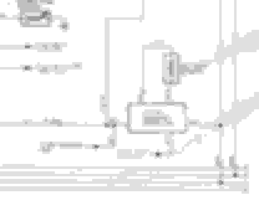
The 1988 FSM shows the following testing procedure for the Overdrive Relay:
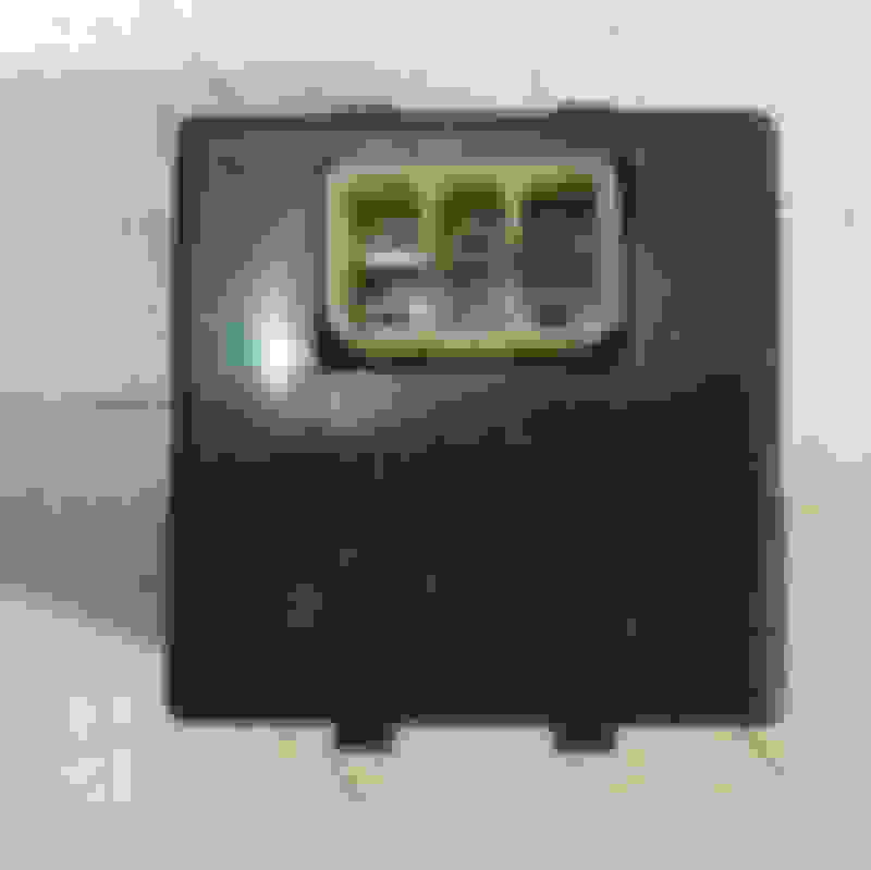
BUT, the O/D Relay on my 4Runner has 5 terminals, not 4, and looks likes this:
Anyone have the testing instructions for this 5 terminal O/D Relay? My concern is the procedure involving application of 12 V Battery voltage. I don't want to to do this until I can confirm which terminals should receive voltage.
Last edited by CCDave; 06-10-2018 at 03:02 PM.
Reason: issue resolved
Inspect harness/relay block connector where relay plugs into and see if it does indeed have 5 wires to it. Compare wire colors to those on schematic.
I have 5 wires on the connector. After another look in the FSM I realized the 4 wire connector schematic and O/D Relay test procedures are for the A43D/2WD. I don't see an O/D Relay test in the A340H/4WD section of the FSM so this suggests there is not a test for this 5 wire O/D Relay. I also could not find a schematic that shows the 5 wire O/D Relay.
Any way, here's a comparison of the 4 and 5 wire connectors:
The 4 wires in the Schematic:
Black/Yellow (To Solenoid) - Blue (From Cruise Control Main Switch)
Black/Red (from EFI ECU) - Black/Green (To EFI ECU via Cruise Control Computer?)
The 5 wires on my connector:
White/Black - Green - Green/Red
Black/Yellow - BLANK - Red/Yellow
I quickly skimmed the A340H section in my 1987 FSM and did not see a test for your version either, however the test you are looking for may be in other A340H specific manuals published by Toyota.
The beginning of my FSM lists a supplement manual "A340E, A340H Automatic Transmission Manual (Publication No. 36265E)".
The system may also be shown in the separate Electrical Wiring Diagram Manual (Publication No. EWD025U).
Thanks. I have the 1991 A340H manual, but it doesn't have the test or wiring diagram so I'll focus on finding the wiring diagram manual.
... The 5 wires on my connector:
White/Black - Green - Green/Red
Black/Yellow - BLANK - Red/Yellow
Dace,
(Chances are relay is good, wiring is bad (see signature - I have not seen a bad relay since I joined in 2012, except this - BWAH-HAH-HAH).
Yes, finding the manual is very important.
Short of that:
1) You can take the info above^^^ re: approx 150 ohms across the coil.
2) Look at thickness of wires. Most likely, the wires leading to the coil would be thinner than the load wires. On a good relay you would get the 100 ohms or 150 ohms or something between those tow thin wires.
3) The other 3 wires would be thicker.
4) One load wire will be open to one (normally-open) and have 0 ohm to the other (normally-closed) when relay is off
5) Vice-versa.
....
Well, if I apply 12v to the wrong pins this relay will need an evidence bag.
LOL! Yes.
That's why I suggest the resistance checks above. Won't hurt a thing. When u do, report back with graphics. I am not good with visualizing words.
A picture paints a thousand words. A picture of beat up relay, a millionn laughs.
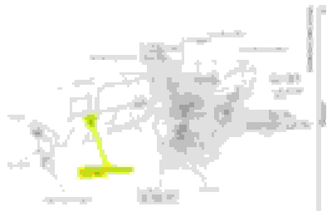
Additional info about the oil warning computer. This drawing is from the 1987 New Car Features manual and shows the Transmission Oil Warning Computer and it's location.
I have an 88 FSM, so for those with an 87 FSM I'm curious if this transmission oil warning computer is identified in there. According to the label on the drawing, it looks to be specific to the Turbo SR5.
What I haven't been able to find info on is the location of the O/D Relay in the 87 4Runner Turbo. The 87 wiring diagrams have the O/D relay, so that suggests it has to be there somewhere. The 88 FSM says it's located on the pedal bracket, but there is not one on my 4runner.

 06-03-2018, 01:08 PM