
88 Pickup radio/console wiring help
 03-27-2013, 04:12 PM
#1
Registered User
Thread Starter

Join Date: Jan 2013
Location: Iowa
Posts: 43
Likes: 0
Received 0 Likes
on
0 Posts
88 Pickup radio/console wiring help
Trying to figure out a jumbled mess of wiring behind my center console as the previous owner cut of the OEM connectors and twisted wires together to fit his stereo...
I've looked at the haynes manual, the service manual, and multiple aftermarket radio diagrams but it seems like there is no certain wiring diagram.
I picked up a replacement pigtail off of ebay for the radio and I clipped some plugs from the junkyard.
Any help or direction would be appreciated thanks!
This is what I have....
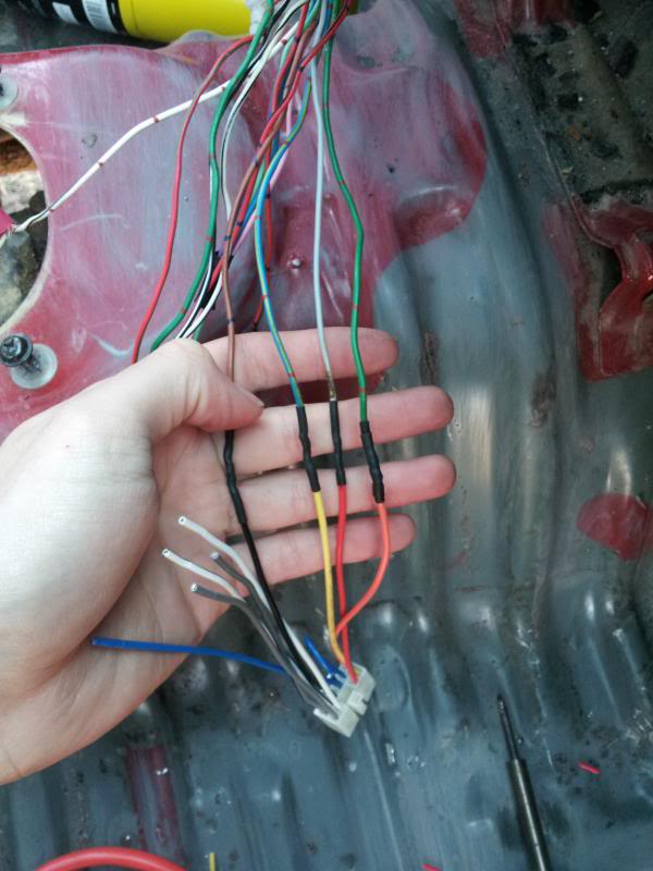
Brown - radio ground
Blue/yellow - 12V constant
Gray - 12V IGN switch
Green - illumination
Red/green - + cig lighter
White/black - GND
I think these are OEM speaker wires, right and left, pos and neg, but i'm not sure where they come out so I'm going to wire the speakers into the connector with my own wire.
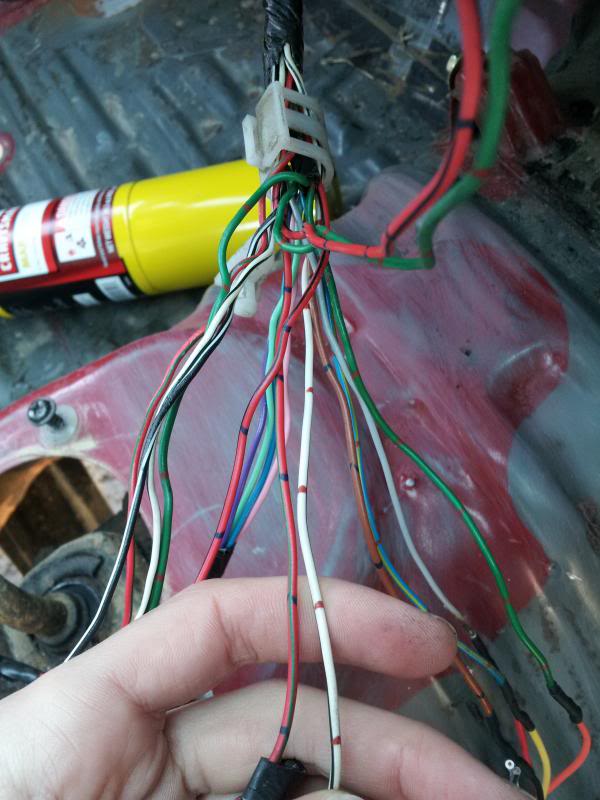
I still have a red/black wire left over, which i think is a dimmer wire.
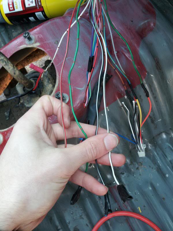
and a black/white, white/black, green, and red/green. From what i've seen, black/white can also be 12v constant. White/black is ground, and red/green is 12v switched
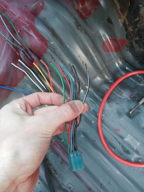
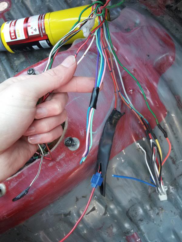
and finally i have what i think is a clock plug, i'm not sure why it has 6 wires coming out of it because the service manual only has 4 wires.
I've looked at the haynes manual, the service manual, and multiple aftermarket radio diagrams but it seems like there is no certain wiring diagram.
I picked up a replacement pigtail off of ebay for the radio and I clipped some plugs from the junkyard.
Any help or direction would be appreciated thanks!
This is what I have....
Brown - radio ground
Blue/yellow - 12V constant
Gray - 12V IGN switch
Green - illumination
Red/green - + cig lighter
White/black - GND
I think these are OEM speaker wires, right and left, pos and neg, but i'm not sure where they come out so I'm going to wire the speakers into the connector with my own wire.
I still have a red/black wire left over, which i think is a dimmer wire.
and a black/white, white/black, green, and red/green. From what i've seen, black/white can also be 12v constant. White/black is ground, and red/green is 12v switched
and finally i have what i think is a clock plug, i'm not sure why it has 6 wires coming out of it because the service manual only has 4 wires.
 03-27-2013, 05:03 PM
#2

The wiring is definately standardised. But I can't find any question marks in your post to answer any questions.
Guessing you've already seen this, and have the FSM?
http://www.installdr.com/Harnesses/Toyota-Wiring.pdf
That "extra" plug is "plug B", it contains the rear speakers and illumination ground.
The speaker end of the wires are taped up to the harness under the dash near the speaker vent holes.
If you wanna try again with questions and question marks it'd be a little easier to follow for me
Oh those four wires are probably the clock, colors match up. pg 1467 in the 88 FSM pdf.
03-27-2013, 05:16 PM
#3
Registered User
Thread Starter
Join Date: Jan 2013
Location: Iowa
Posts: 43
Likes: 0
Received 0 Likes
on
0 Posts
Thanks, really just wanted confirmation that what I've done so far is identified correctly.
So the 4 wires that have black tape on the end are for the clock, sorry I missed it. kinda obvious from pg 1467, I guess i was more concerned with plug B and I mixed up my pigtails and found the right one for the clock.
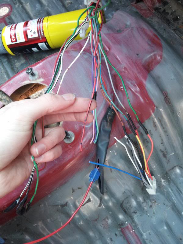
Question is, what is that extra red/black wire for in picture #4? Radio dimming?
Thanks for the quick response!
So the 4 wires that have black tape on the end are for the clock, sorry I missed it. kinda obvious from pg 1467, I guess i was more concerned with plug B and I mixed up my pigtails and found the right one for the clock.
Question is, what is that extra red/black wire for in picture #4? Radio dimming?
Thanks for the quick response!
03-27-2013, 05:29 PM
#4
Yeah think that is the ground wire for the lights. In my truck it was on a single spade connector seperate from everything else, but i have a 4 channel so had to attach it to the 2nd plug. It's pin N on the 4 channel system,or b4 depending what plug diagram.
You can test it, meter to power and that wire, voltage should change with the dimmer knob.
You can test it, meter to power and that wire, voltage should change with the dimmer knob.

Thread
Thread Starter
Forum
Replies
Last Post
steve miller
General Electrical & Lighting Related Topics
2
10-10-2015 01:40 AM


