OBA using your A/C Compressor and an air tank.
 08-06-2011, 08:20 PM
#1
Contributing Member
Thread Starter
iTrader: (3)
OBA using your A/C Compressor and an air tank.
Well, the time finaly came when I decided to put my A/C compressor back into my rig(plus the radiator was out anyways for its epic battle of rightness and by the EIGHTH one I had plenty of time to do this project ). I'd had it out along with all the bracketry due to having to pull the timing cover to reseal it a long while ago. While it was out I replaced the bearing on the pulley and upon reassembly the clutch gap check failed and was WAAAY to close to the pulley. After getting the right shims from TOYOTA I put it all back together and also replaced the idler pulley. It's runs perfectly quiet now!
I've been wanting to do this project for YEARS. Plus, my R-12 system crapped out back in '03 and I haven't had the need for A/C anyways....I'd read up on it on pirate, Ih8mud and more recently on HERE.
***The ultimate goal here was to have a clean install, be functional and last for years of service.***
***Also, this project was based of the 22R-E motor platform. Just incase SOMEONE can't figure that out. However, this basics of the system components is the same.***
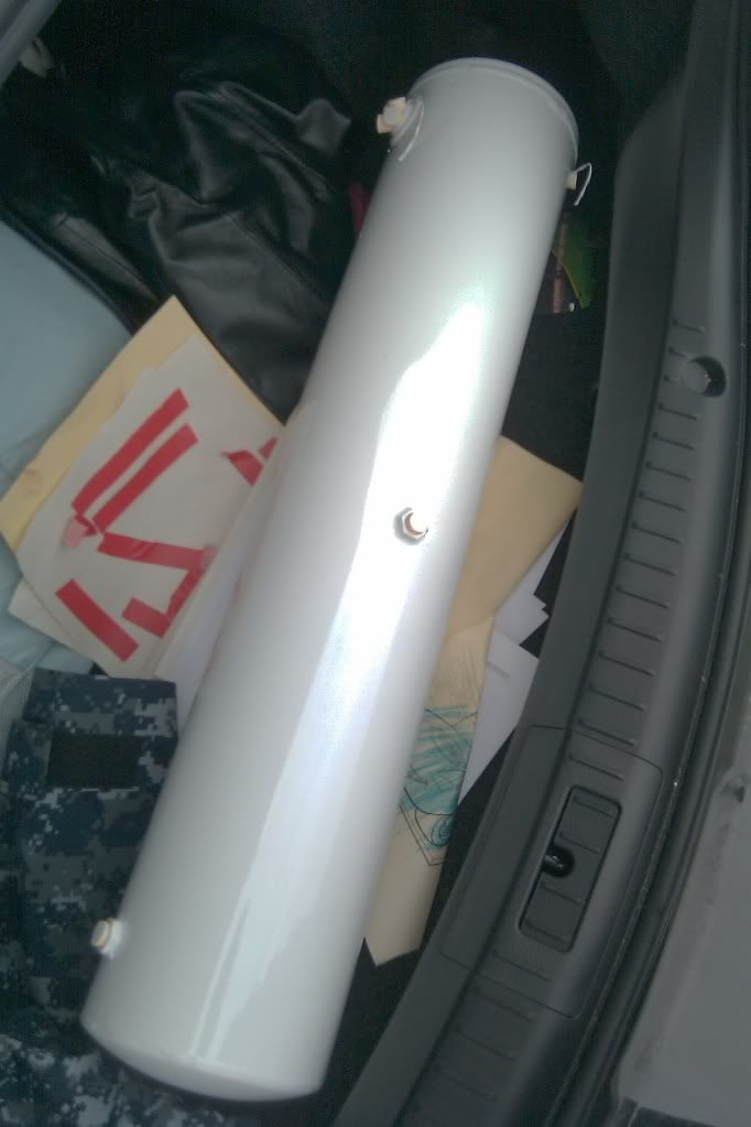
I knew I wanted to run a tank and that was my big road block. As with all my unique projects, I'm really cheap...and lazy...but meticulous. A guy at work had mentioned that he was throwing an air compressor away and out of shear curiousity I asked what kind. Turned out to be a twin tank Emglo. He had robbed everything off of it because one of the tanks was completely rotted out. So, he gave me the good tank.
). I'd had it out along with all the bracketry due to having to pull the timing cover to reseal it a long while ago. While it was out I replaced the bearing on the pulley and upon reassembly the clutch gap check failed and was WAAAY to close to the pulley. After getting the right shims from TOYOTA I put it all back together and also replaced the idler pulley. It's runs perfectly quiet now!I've been wanting to do this project for YEARS. Plus, my R-12 system crapped out back in '03 and I haven't had the need for A/C anyways....I'd read up on it on pirate, Ih8mud and more recently on HERE.
***The ultimate goal here was to have a clean install, be functional and last for years of service.***
***Also, this project was based of the 22R-E motor platform. Just incase SOMEONE can't figure that out. However, this basics of the system components is the same.***
I knew I wanted to run a tank and that was my big road block. As with all my unique projects, I'm really cheap...and lazy...but meticulous. A guy at work had mentioned that he was throwing an air compressor away and out of shear curiousity I asked what kind. Turned out to be a twin tank Emglo. He had robbed everything off of it because one of the tanks was completely rotted out. So, he gave me the good tank.
Last edited by BigBluePile; 08-10-2011 at 01:52 PM.
 08-06-2011, 08:23 PM
#2
Contributing Member
Thread Starter
iTrader: (3)
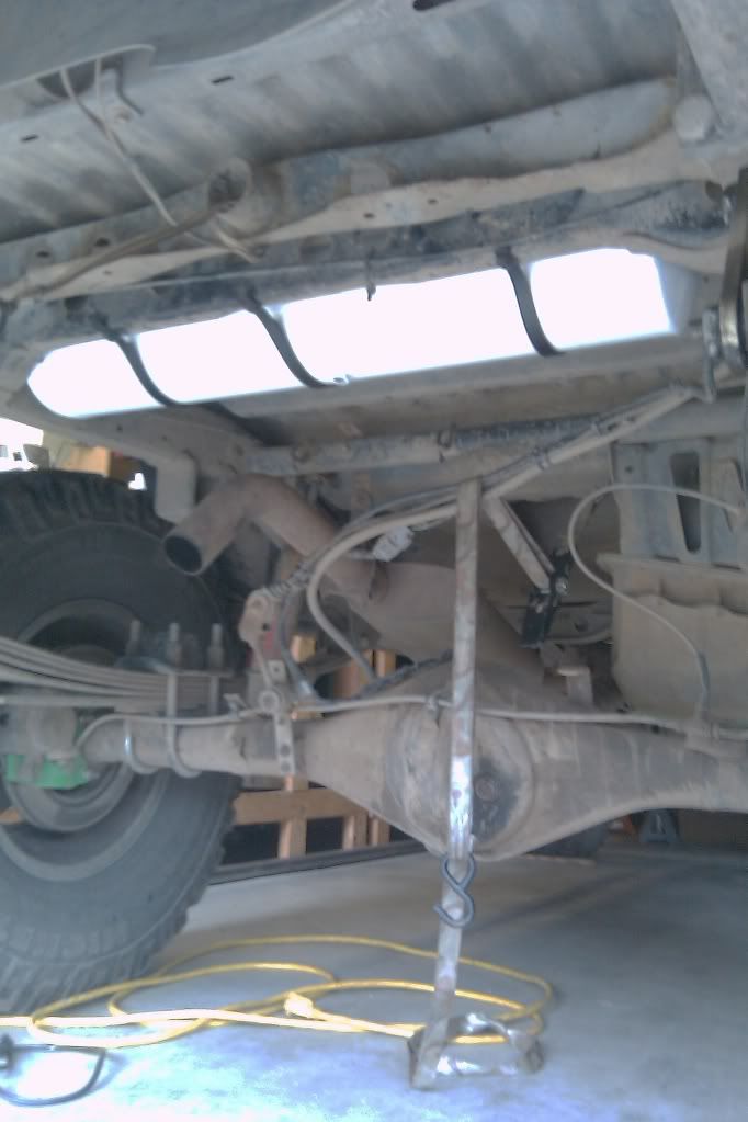
Now these tanks will fit PERFECTLY between the frame rails!!! Yay!!! 
Unfortunately, this tank needed some love and I wasn't about to put a tank on that would fall apart and rot out. First I ground off the end cap. Now, I was hoping that it was a slip fit but it wasn't. Straight up butt joint and I ended up, as you can imagine, getting the metal pretty thin.
It was pretty gross inside. Not as bad as the other tank though. So, I contined to grind off all the old bracket parts and cleaned up the tank as best I could. Ended up actually taking about 1.5" off the tank.
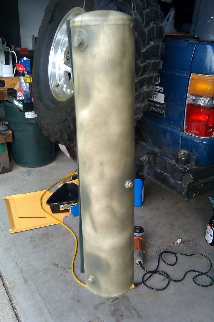
I had it media blasted and then the end cap welded back together and had two 1/4" NPT fittings welded in. Giving me three total ports, one of which was an original port 1/2" NPT, IIRC...
Then I had the tank painted with "paint".
Unfortunately, this tank needed some love and I wasn't about to put a tank on that would fall apart and rot out. First I ground off the end cap. Now, I was hoping that it was a slip fit but it wasn't. Straight up butt joint and I ended up, as you can imagine, getting the metal pretty thin.
It was pretty gross inside. Not as bad as the other tank though. So, I contined to grind off all the old bracket parts and cleaned up the tank as best I could. Ended up actually taking about 1.5" off the tank.
I had it media blasted and then the end cap welded back together and had two 1/4" NPT fittings welded in. Giving me three total ports, one of which was an original port 1/2" NPT, IIRC...
Then I had the tank painted with "paint".
Last edited by BigBluePile; 08-06-2011 at 08:28 PM.
08-06-2011, 08:48 PM
#3
Contributing Member
Thread Starter
iTrader: (3)
The next headache was mounting the tank. I just happened across some steel banding of nominal thickness and with three straps, some sheet metal screws, rubber sheet and black spray paint later, it was mounted!
Again, a lot of the stuff for this project I all ready had or "aquired" locally.
Once that was done I went ahead and bought a tank sealer kit for motorcycle gas tanks(VERY expensive, BTW). Now, if you've never used one of these kits, it's pretty straight forward but be aware of the chemicals and do it in a VERY well ventalilated area. This will put a very nice rubber coating on the inside of the tank and will hopefully prevent any kind of corrosion. Now take your time doing this(if you chose too, which you don't have too...) and make sure you get the ENTIRE inside coated. Its like pouring molases into a solid container and guessing where it's flowed too...ugh...it'll take a good couple of pour ins, tilt-a-whirls, pour outs before you get all the inside done. I still have sealer left over to do another tank.
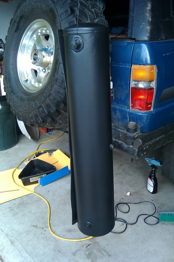
So, I primered the tank and spray a rubberized coating on it to help reduce rock damage and prolong the paint integrity.
The tank is made up of a couple of components. The input and output ports have quick disconnects on them to allow for easier removal of the tank or rear bumper. Also, on the bottom of the tank, centered, I put a simple bleed valve to empty the tank. Finally, on the input side, I installed a 125psi popoff valve JUST IN CASE the system over charges.
Now on to the fittings(of which there are a bunch...), air manifold, hose and intergration of the A/C compressor....
Again, a lot of the stuff for this project I all ready had or "aquired" locally.
Once that was done I went ahead and bought a tank sealer kit for motorcycle gas tanks(VERY expensive, BTW
). Now, if you've never used one of these kits, it's pretty straight forward but be aware of the chemicals and do it in a VERY well ventalilated area. This will put a very nice rubber coating on the inside of the tank and will hopefully prevent any kind of corrosion. Now take your time doing this(if you chose too, which you don't have too...) and make sure you get the ENTIRE inside coated. Its like pouring molases into a solid container and guessing where it's flowed too...ugh...it'll take a good couple of pour ins, tilt-a-whirls, pour outs before you get all the inside done. I still have sealer left over to do another tank.So, I primered the tank and spray a rubberized coating on it to help reduce rock damage and prolong the paint integrity.
The tank is made up of a couple of components. The input and output ports have quick disconnects on them to allow for easier removal of the tank or rear bumper. Also, on the bottom of the tank, centered, I put a simple bleed valve to empty the tank. Finally, on the input side, I installed a 125psi popoff valve JUST IN CASE the system over charges.
Now on to the fittings(of which there are a bunch...
), air manifold, hose and intergration of the A/C compressor....
Last edited by BigBluePile; 08-10-2011 at 11:01 AM.
 J/K. Looks like a nice score on the tank.
Trending Topics
08-09-2011, 07:44 AM
#8
Contributing Member
Thread Starter
iTrader: (3)
Continuation...
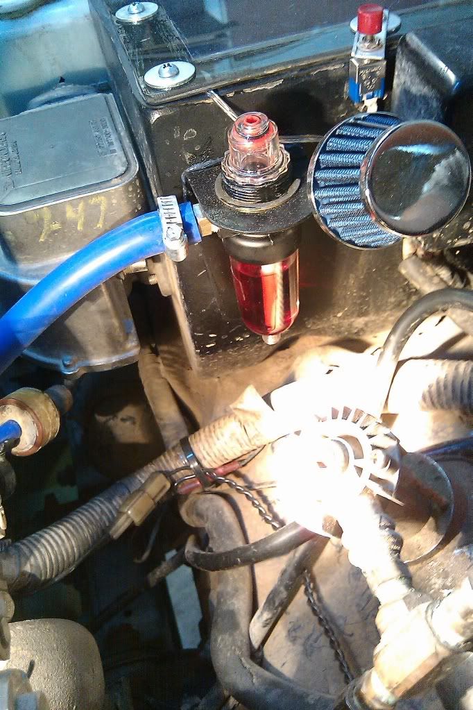
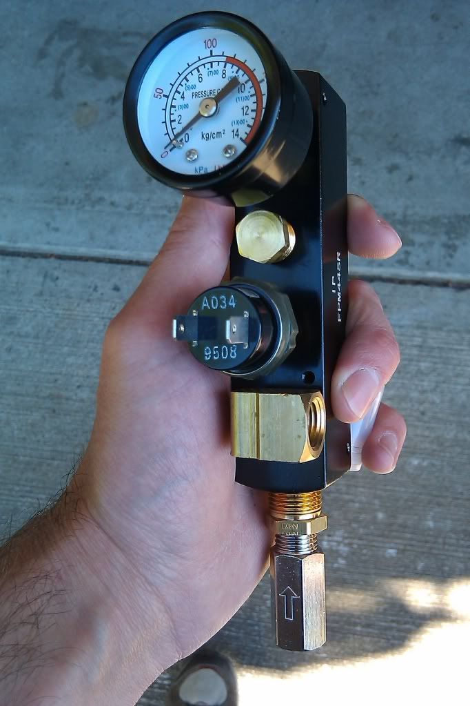
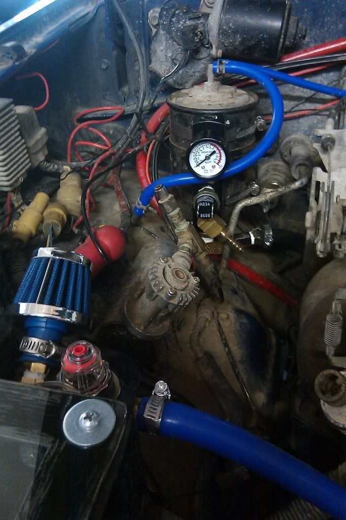
Next project was mounting the last three parts of this system: inline oiler, water seperator and the pencil air manifold(its a "4 into 1" style).
Some of the compents I ordered thru Amazon and I'm sure there are other resources that these can be attained from.
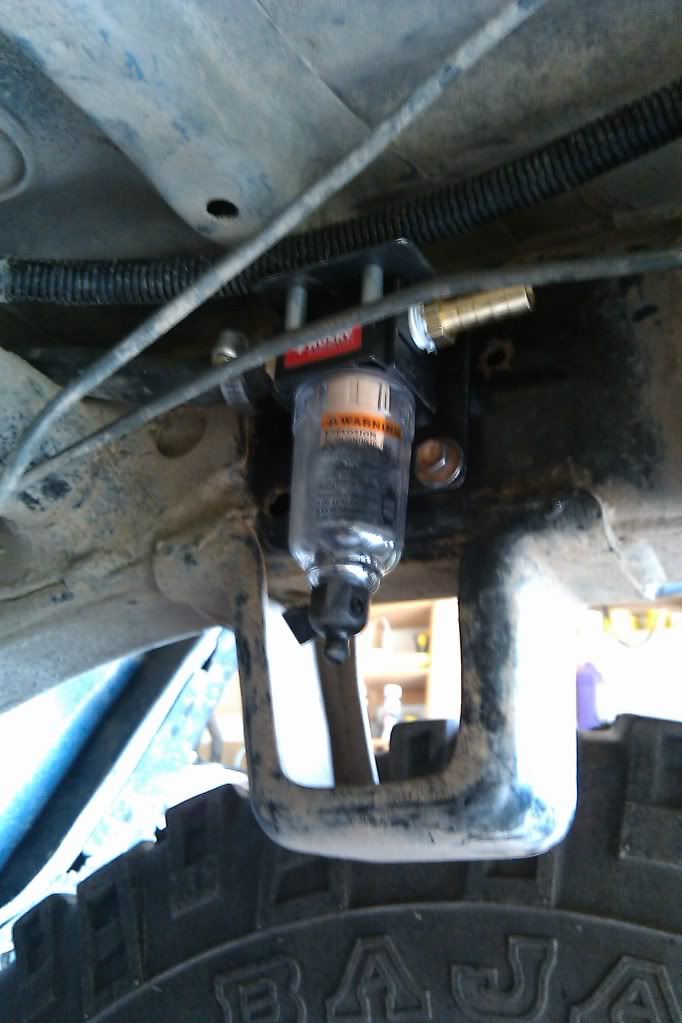
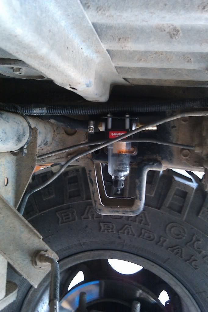
The micro water seperator was from Home Depot.
The manifold, Viair 85-105psi pressure switch, check valve and the 1/4" to 1/8" NPT adapter was from Amazon.
The micro inline oiler and all the brass fittings, adapters(3/8" to 1/4" NPT), quick disconnects and hose barbs were from Napa. All fittings are 1/4" NPT.
The Spectre valve cover filter for the intake of the A/C compressor is from Autozone.
The 3/8" air hose and micro pressure gauge and various hardware I all ready had.
All the brackets I fabricated from various pieces of aluminum. The seperator, oiler and manifold came with zero type of mounting anything and I had to make stuff work.
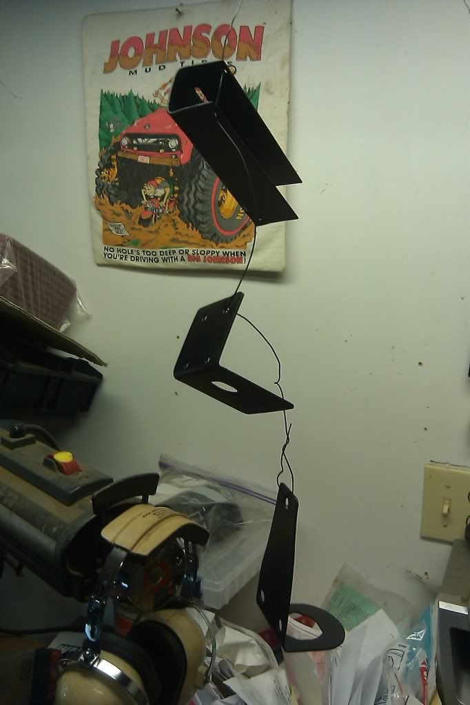
-The oiler itself should have came with a threaded ring and I ended up using a c-clip to mount it onto it's bracket. Then mounted the L-bracket to my air filter box.
-The seperator had four threaded holes that were 8-32", IIRC. So, I used spacers and some all thread and locknuts to secure it. Then I drilled and taped holes in the frame rail and mounted it behind the upper bumpstop. If this piece breaks or fails, I'll probably move it up inside the bed somewhere.
-The pencil manifold was mounted with a U-channel formed from aluminum and bolted together. I then used large hose clamps to secure the manifold to the charcoal canister.
Next: electrical and VSV....
Some of the compents I ordered thru Amazon and I'm sure there are other resources that these can be attained from.
The micro water seperator was from Home Depot.
The manifold, Viair 85-105psi pressure switch, check valve and the 1/4" to 1/8" NPT adapter was from Amazon.
The micro inline oiler and all the brass fittings, adapters(3/8" to 1/4" NPT), quick disconnects and hose barbs were from Napa. All fittings are 1/4" NPT.
The Spectre valve cover filter for the intake of the A/C compressor is from Autozone.
The 3/8" air hose and micro pressure gauge and various hardware I all ready had.
All the brackets I fabricated from various pieces of aluminum. The seperator, oiler and manifold came with zero type of mounting anything and I had to make stuff work.
-The oiler itself should have came with a threaded ring and I ended up using a c-clip to mount it onto it's bracket. Then mounted the L-bracket to my air filter box.
-The seperator had four threaded holes that were 8-32", IIRC. So, I used spacers and some all thread and locknuts to secure it. Then I drilled and taped holes in the frame rail and mounted it behind the upper bumpstop. If this piece breaks or fails, I'll probably move it up inside the bed somewhere.
-The pencil manifold was mounted with a U-channel formed from aluminum and bolted together. I then used large hose clamps to secure the manifold to the charcoal canister.
Next: electrical and VSV....
Last edited by BigBluePile; 08-10-2011 at 10:36 AM.
08-09-2011, 08:18 AM
#9
Registered User
lookin good man, i wish i could do the same but i think my steering box is gonna be in the way (dont have ac now) i was thinking, couldnt you just mount an electric compressor (motor and pump) somwhere and do the same with the tanks? hermm
 08-10-2011, 10:35 AM
#12
Contributing Member
Thread Starter
iTrader: (3)
Continuation...
The A/C system has a few interlocks/components that all communicate to the little A/C computer behind the glove box.
-First one is a signal from the coil to indicate the motor is running.
-Second is a freon pressure switch. This switch interups the power to the magnet on the A/C clutch if the system goes below 1 lb(whatever pressure that is) to prevent the system running and damaging the compressor.
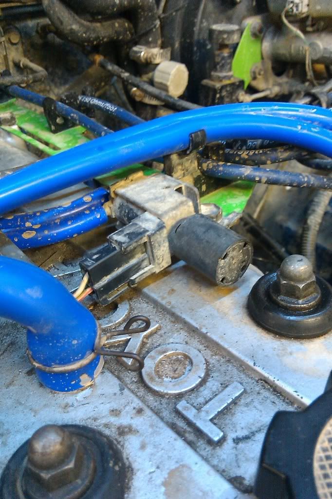
-Third is a VSV that sits on the valve cover that provides an "idle up" conditon when the motor is...well...at idle.
-Fouth is the actual fan speed switch.
I chose to be able to use the A/C switch in the dash instead of "hotwiring" or adding yet ANOTHER switch. Which means that the fan speed switch has to be on but I've always have it running anyways. Eventually, I'm going to run a signal wire up the the A/C switch to tell me when the clutch is engaged/disengaged.
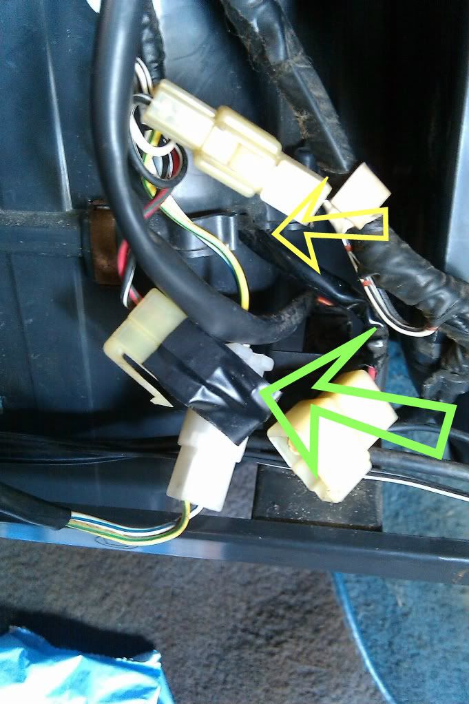
In order to access the pressure switch I pulled the glove box. The switch itself is inside the airbox(yellow). So, I traced it back a few inches to the plug(green), disconnected it and ran a simple jumper wire upline the switch to "fool" the system to think it's properly charged with freon. With that done, I simply tucked the wires back in and reinstalled the glove box.
The VSV that controls the idle sits just back from the oil cap. Mine actually didn't work the first time I turned the system on(it was last used circa 2003ish). After I cycled the A/C switch a few times it started working.
Next up: plumbing...
-First one is a signal from the coil to indicate the motor is running.
-Second is a freon pressure switch. This switch interups the power to the magnet on the A/C clutch if the system goes below 1 lb(whatever pressure that is) to prevent the system running and damaging the compressor.
-Third is a VSV that sits on the valve cover that provides an "idle up" conditon when the motor is...well...at idle.
-Fouth is the actual fan speed switch.
I chose to be able to use the A/C switch in the dash instead of "hotwiring" or adding yet ANOTHER switch. Which means that the fan speed switch has to be on but I've always have it running anyways. Eventually, I'm going to run a signal wire up the the A/C switch to tell me when the clutch is engaged/disengaged.
In order to access the pressure switch I pulled the glove box. The switch itself is inside the airbox(yellow). So, I traced it back a few inches to the plug(green), disconnected it and ran a simple jumper wire upline the switch to "fool" the system to think it's properly charged with freon. With that done, I simply tucked the wires back in and reinstalled the glove box.
The VSV that controls the idle sits just back from the oil cap. Mine actually didn't work the first time I turned the system on(it was last used circa 2003ish). After I cycled the A/C switch a few times it started working.
Next up: plumbing...
08-10-2011, 02:58 PM
#16
Registered User
I had a feeling once we got to th electrical part, my head would explode. lol. Good work man, I think..... And I don't have A/C so this would be a perfect mod for me. 
 08-10-2011, 03:12 PM
#18
Registered User
I think if I could see a diagram, I'd be able to figure it out, (just like I did with that ignition setup of mine) but all this talk about this and that has my head spinning hahahaha.
08-11-2011, 06:17 AM
#19
Contributing Member
Thread Starter
iTrader: (3)
So.....: [BATT(+)]-----FUSE-----ON/OFF SWITCH-------PRESSURE SWITCH-----A/C CLUTCH-----GROUND(-)


