BJ Spacer Install - Wham bam thank you Mam!
 05-23-2014, 07:50 PM
#1
Registered User
Thread Starter
BJ Spacer Install - Wham bam thank you Mam!
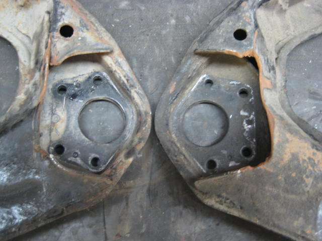
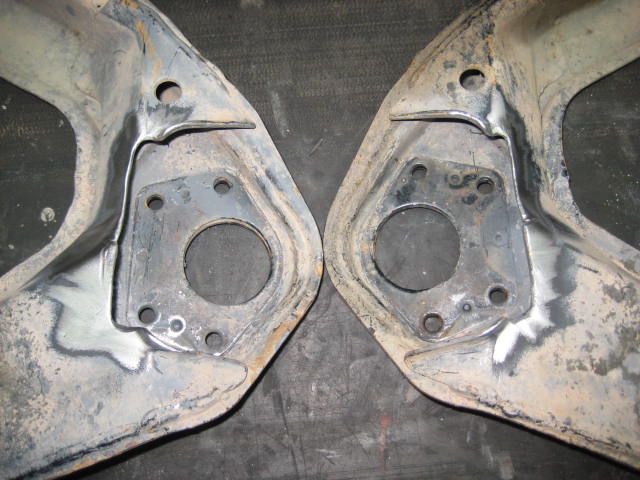
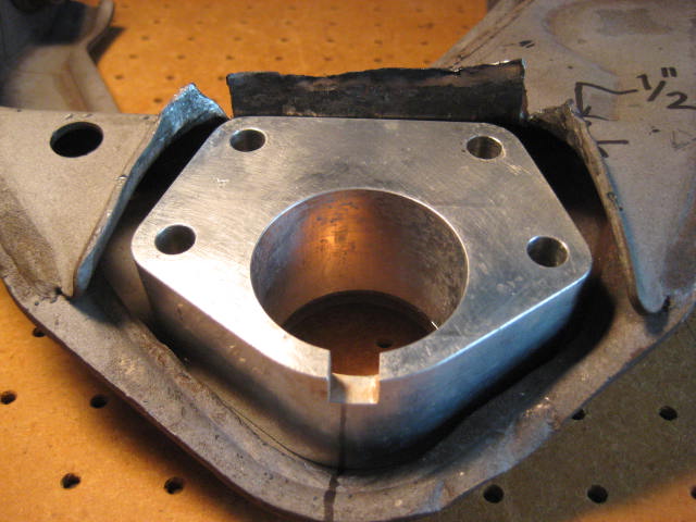
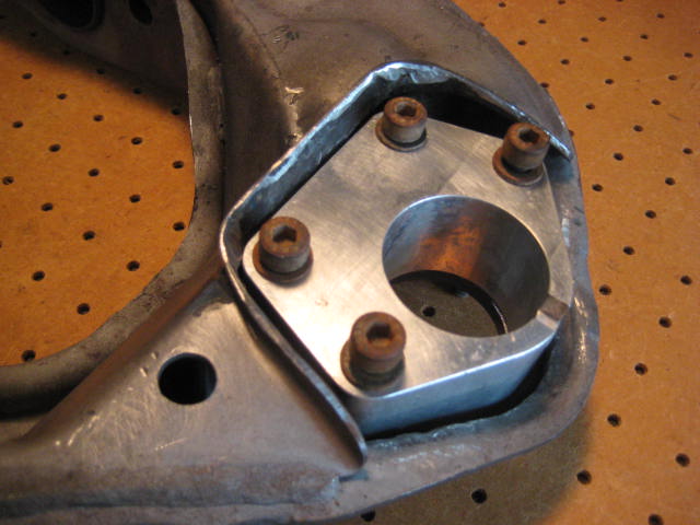
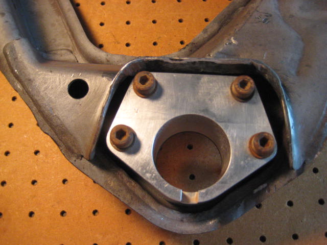
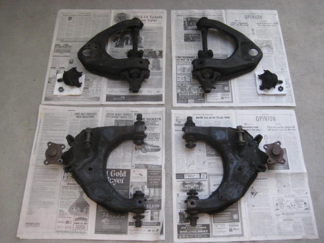
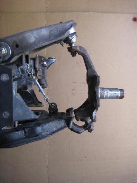
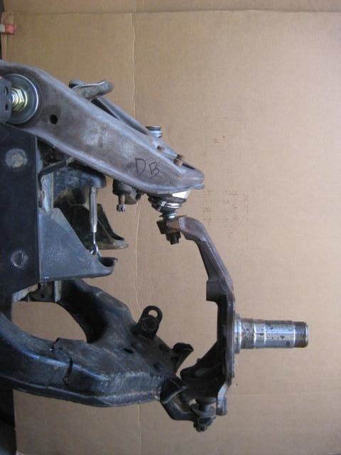
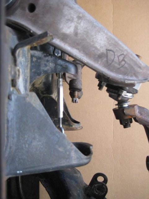
I have been scrapping more and more UCA cores because of BJ Spacer installations lately and I am wondering why all the hack jobs? Here are a set of (4) getting ready to be scrapped.
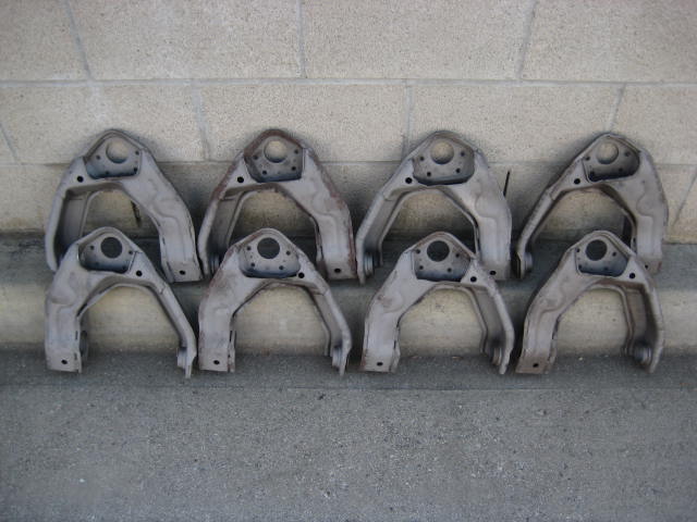
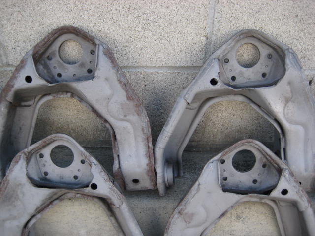

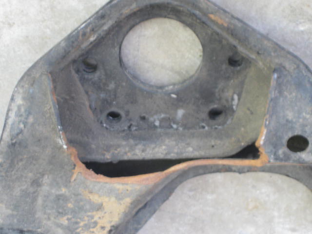
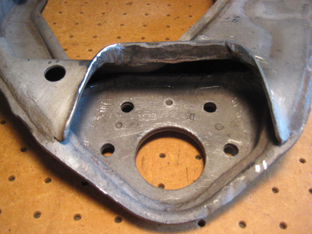
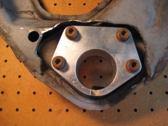
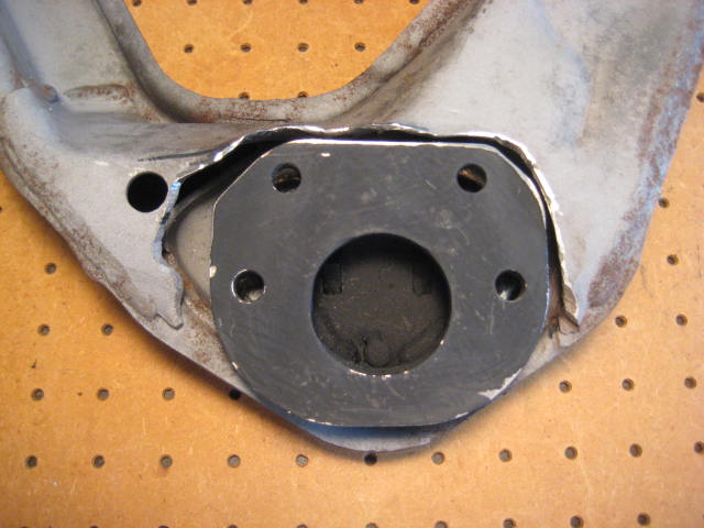
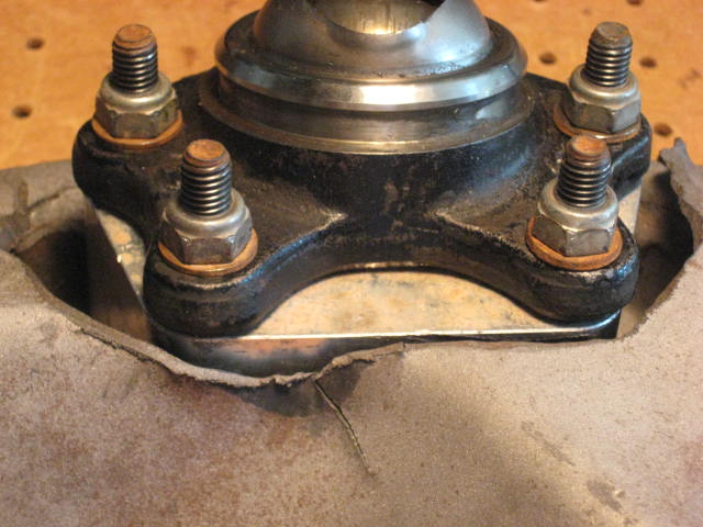
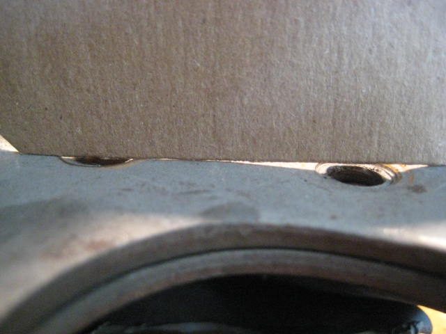
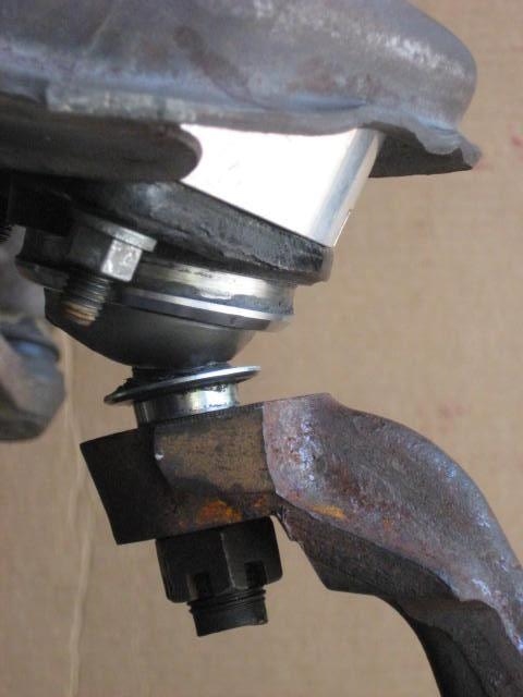
As you can see in the third photo because of the material cut away the UCA has become structurally compromised. I have seen cracks develop in this area a few times on UCAs that have been hacked up for BJ Spacers.
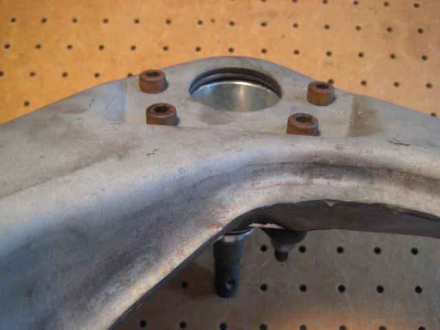
Here is another set of UCA / LCAs a customer sent me that has damage to the UCAs.
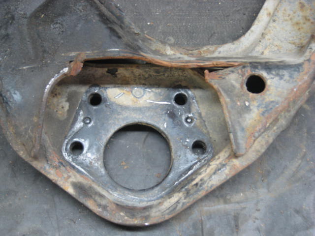
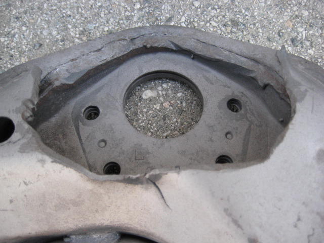
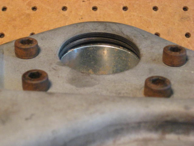
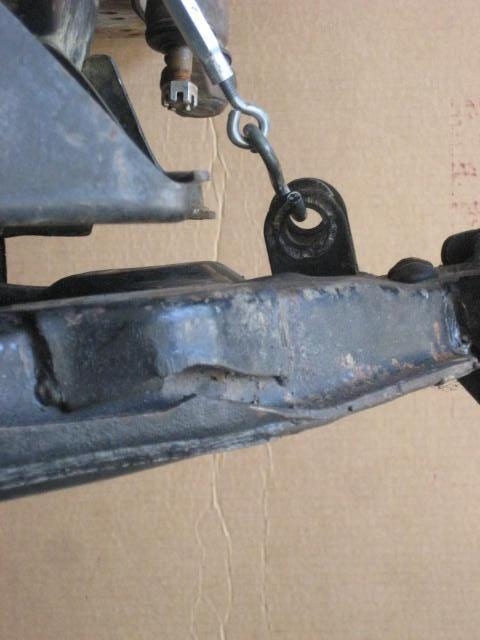
And another example of developing cracks!
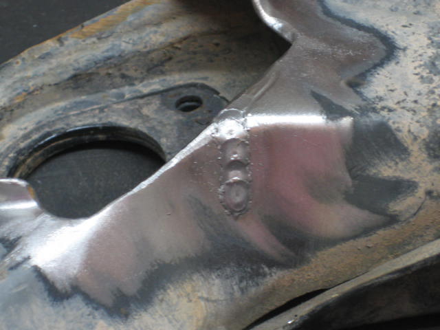
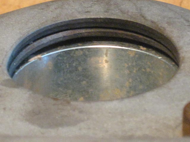
And another, this set I cleaned up with a wire wheel to see how deep the crack went. And while I was at it I ground out the cracks and threw down a couple of weld to fill them in.
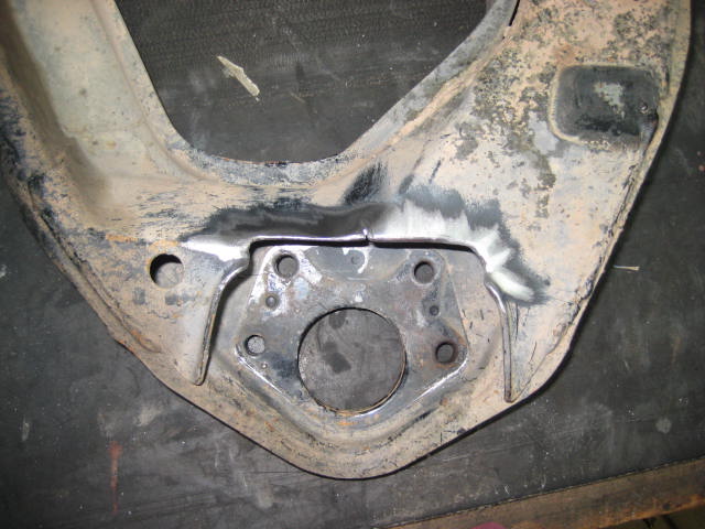
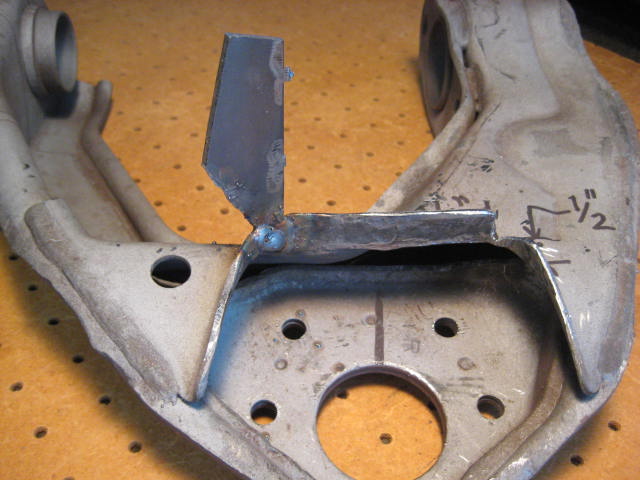
I did some searches here on YT and read a few things about installation but not a whole lot about the cutting of the UCA. A couple of people said that you were only removing a small sliver of material, and that shouldn't matter. I think they are wrong! The section of material that needs to be removed is equivalent to a 1/2" x 1/2" angle of 1/8" thickness and 3" long.
That would be the minimal amount of material to be removed to make the aluminum billet spacers fit, often I see a significant amount more. The section being removed has a bend. When you put a bend in a flat piece of material it strengthens it. Think of a corrugated metal roof panel or putting a dimple die stamp in a flat panel. I could go on but the proof is in the pictures, check your own UCAs if you have BJ Spacers. I hope what you find isn't what I am finding.
A customer gave me his BJ Spacers when he bought a set of Long Arms from me. I thought it might be a good idea take a set of my core UCAs and investigate. I wanted to see what it would be like to make the cuts needed for installation. In my situation I had a set that had all ready undergone a burn recovery to remove the rubber bushings and harvest the steel bushing hardware, so what I was working with was clean, bare metal and I was able to do the work on the bench. Anyway here is what I came up with.
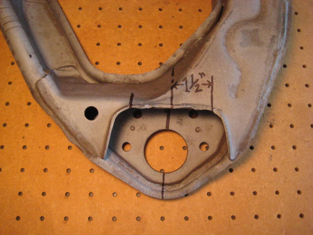
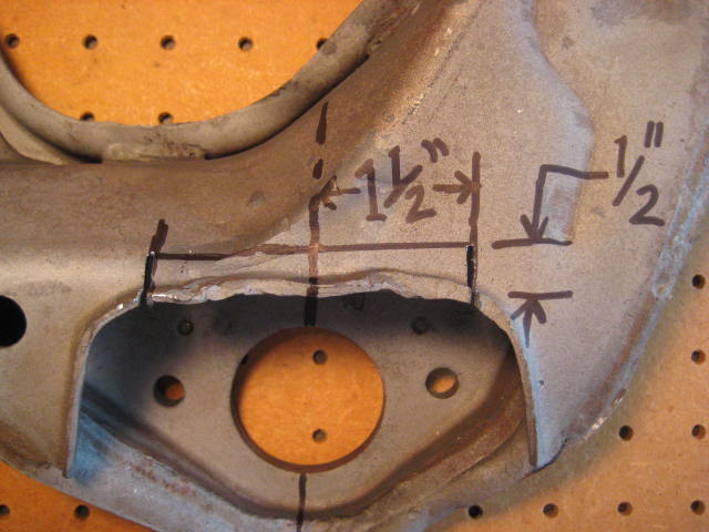
First, find the center line and measure out 1-1/2" either side.
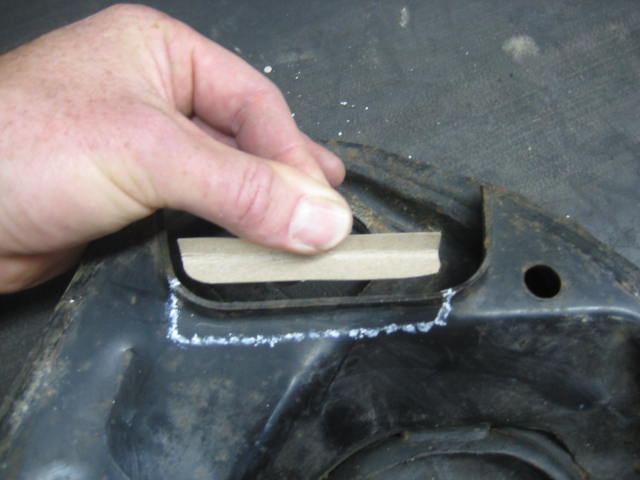
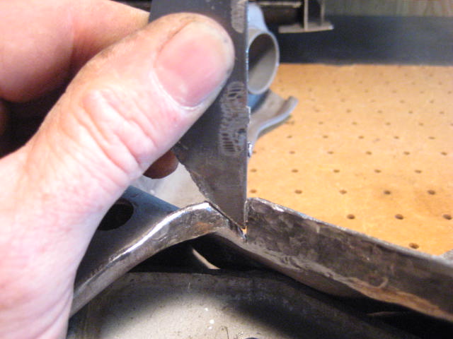
Then make two cuts about 1/2 deep.
Then flatten out the 90 degree bend. In my case this area was beat up a little so I had to hammer and grind flush.
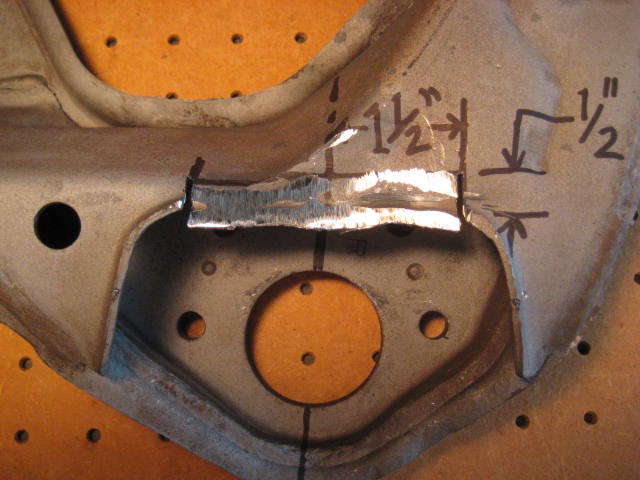
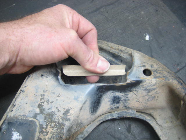
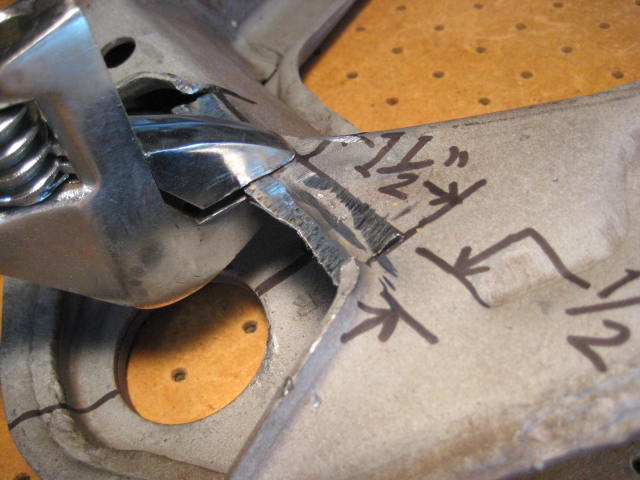
Then get I took a large crescent wrench and relocated the bend deeper into the UCA.
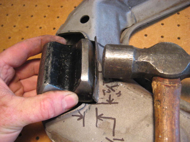
I had to use a hammer and dolly to clean it up a bit and get it straight.
Then a placed the BJ spacer in position and checked clearances.
A bit more shaping and refining was needed, then I cut and ground the lip flush.
Found some old 1/8" scap metal and selected a chunk.
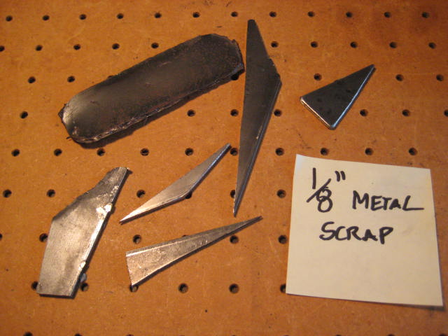
I then shaped a piece till it fit.
Tack welded the piece in place the cut off the excess. Repeated the process for the other side.
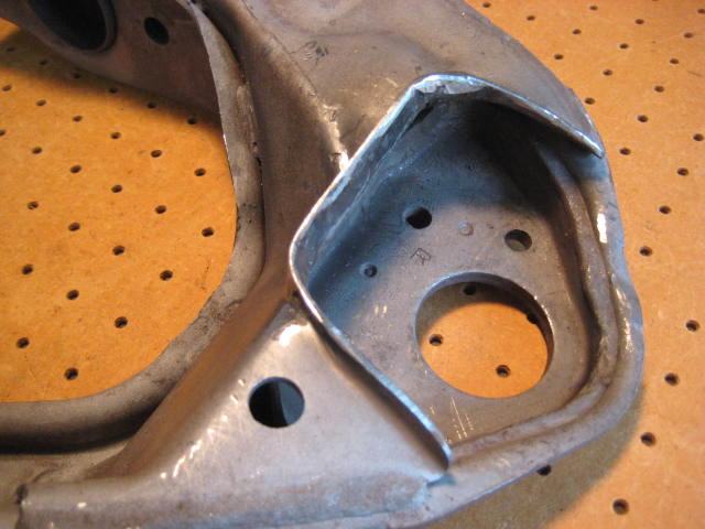
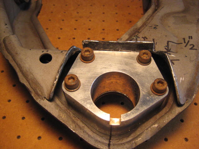
Then I bolted up the spacer and double checked the fit.
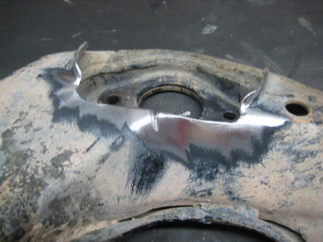
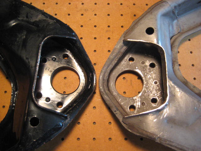
Compare my modified UCA to the hack job version.
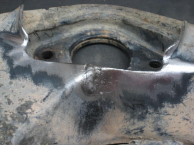
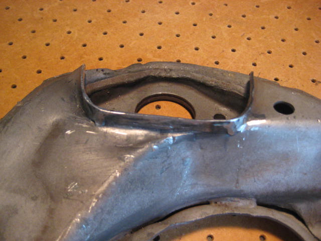
Compare my modified UCA to an unmodified stock UCA.
For you guys out there considering a set of BJ Spacers, take into consideration the information I have presented. Are you going to be lazy and do the modification with the UCA on the rig? If you are have fun being contortionist under your rig with a cut off wheel or sawzall? If that is your method you will end up with a hack job and a structurally compromised UCA.
Take the time to do it right! Remove the UCA, do the metal work! If you take it to a shop, tell them what you want! Don't end up with a "Wham bam thank you Mam" install job!
As you can see in the third photo because of the material cut away the UCA has become structurally compromised. I have seen cracks develop in this area a few times on UCAs that have been hacked up for BJ Spacers.
Here is another set of UCA / LCAs a customer sent me that has damage to the UCAs.
And another example of developing cracks!
And another, this set I cleaned up with a wire wheel to see how deep the crack went. And while I was at it I ground out the cracks and threw down a couple of weld to fill them in.
I did some searches here on YT and read a few things about installation but not a whole lot about the cutting of the UCA. A couple of people said that you were only removing a small sliver of material, and that shouldn't matter. I think they are wrong! The section of material that needs to be removed is equivalent to a 1/2" x 1/2" angle of 1/8" thickness and 3" long.
That would be the minimal amount of material to be removed to make the aluminum billet spacers fit, often I see a significant amount more. The section being removed has a bend. When you put a bend in a flat piece of material it strengthens it. Think of a corrugated metal roof panel or putting a dimple die stamp in a flat panel. I could go on but the proof is in the pictures, check your own UCAs if you have BJ Spacers. I hope what you find isn't what I am finding.
A customer gave me his BJ Spacers when he bought a set of Long Arms from me. I thought it might be a good idea take a set of my core UCAs and investigate. I wanted to see what it would be like to make the cuts needed for installation. In my situation I had a set that had all ready undergone a burn recovery to remove the rubber bushings and harvest the steel bushing hardware, so what I was working with was clean, bare metal and I was able to do the work on the bench. Anyway here is what I came up with.
First, find the center line and measure out 1-1/2" either side.
Then make two cuts about 1/2 deep.
Then flatten out the 90 degree bend. In my case this area was beat up a little so I had to hammer and grind flush.
Then get I took a large crescent wrench and relocated the bend deeper into the UCA.
I had to use a hammer and dolly to clean it up a bit and get it straight.
Then a placed the BJ spacer in position and checked clearances.
A bit more shaping and refining was needed, then I cut and ground the lip flush.
Found some old 1/8" scap metal and selected a chunk.
I then shaped a piece till it fit.
Tack welded the piece in place the cut off the excess. Repeated the process for the other side.
Then I bolted up the spacer and double checked the fit.
Compare my modified UCA to the hack job version.
Compare my modified UCA to an unmodified stock UCA.
For you guys out there considering a set of BJ Spacers, take into consideration the information I have presented. Are you going to be lazy and do the modification with the UCA on the rig? If you are have fun being contortionist under your rig with a cut off wheel or sawzall? If that is your method you will end up with a hack job and a structurally compromised UCA.
Take the time to do it right! Remove the UCA, do the metal work! If you take it to a shop, tell them what you want! Don't end up with a "Wham bam thank you Mam" install job!
 05-23-2014, 09:17 PM
#2
Nice write-up my man! I really like the way you think. It's true what they say after all.
"Anything worth doing, is worth doing right"
"Nothing worth doing, is easy“
"An ounce of prevention, is worth a pound of cure"
"Anything worth doing, is worth doing right"
"Nothing worth doing, is easy“
"An ounce of prevention, is worth a pound of cure"
Last edited by MudHippy; 05-23-2014 at 09:47 PM.
05-24-2014, 09:21 PM
#3
Registered User
Thread Starter
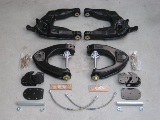
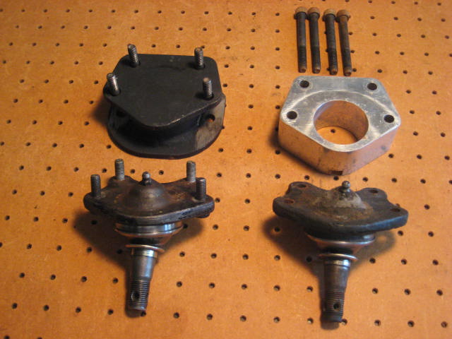
For you guys considering a Blazeland Long Arm kit, a DIY weld up kit, or ordering parts a la carte, and are wondering if Blazeland Upper Control Arm Extension Brackets require the above described modifications, the answer is NO!
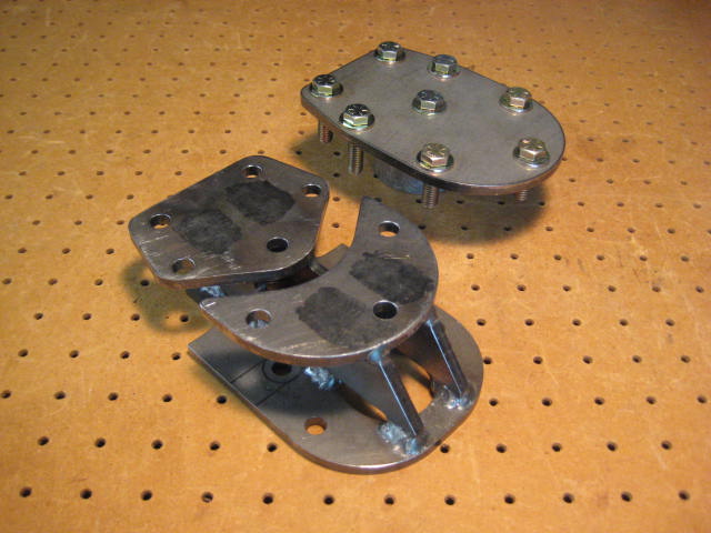
Here is a side by side comparison of the BJ Spacer and the UCA Extension Bracket.
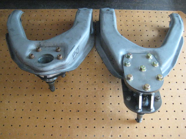
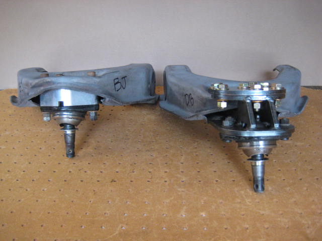
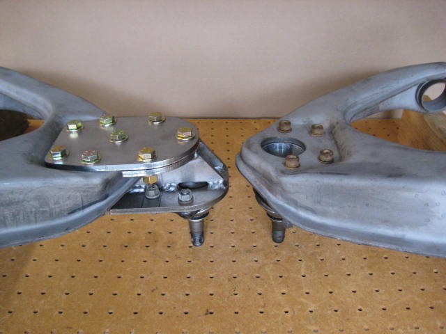
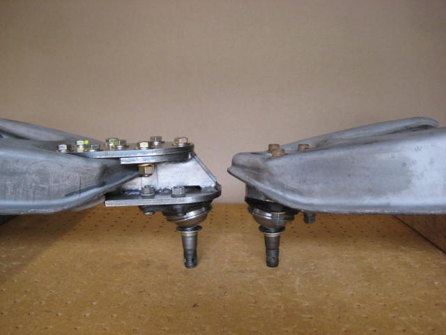
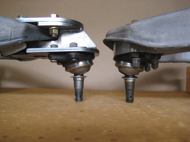
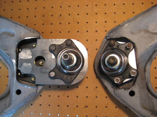
When the UCA is flipped over you can see from the bottom, and that the lip is completely intact and unmodified.
Here is a side by side comparison of the BJ Spacer and the UCA Extension Bracket.
When the UCA is flipped over you can see from the bottom, and that the lip is completely intact and unmodified.
05-25-2014, 10:10 PM
#5
Registered User
Thread Starter
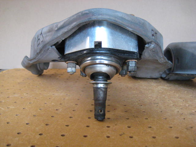
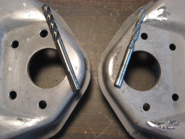
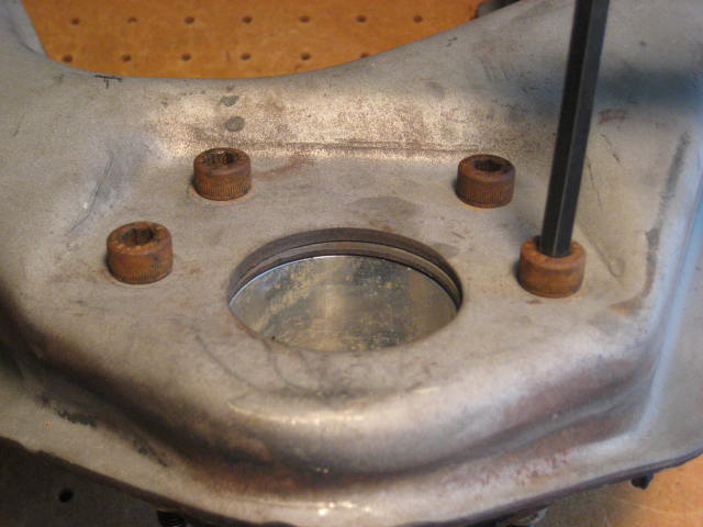
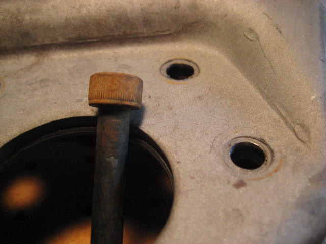
The only modification to the UCA needed to receive the UCA Extension Bracket is to hog out the (4) metric holes to accept the larger hardware.
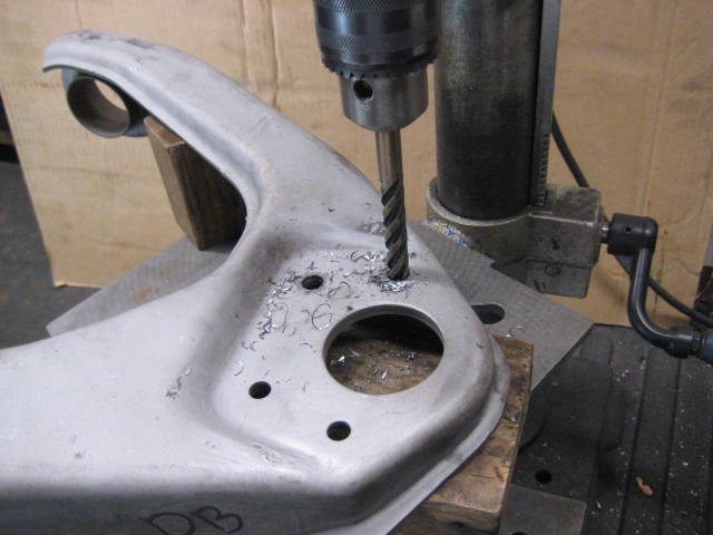
The holes go from 5/16" to 3/8" (.3125 to .3750)
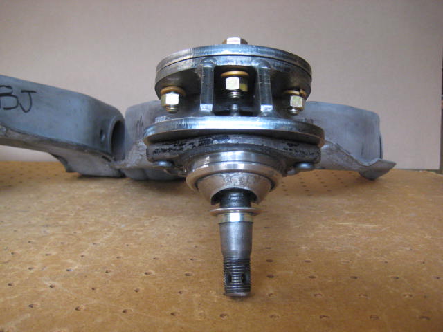
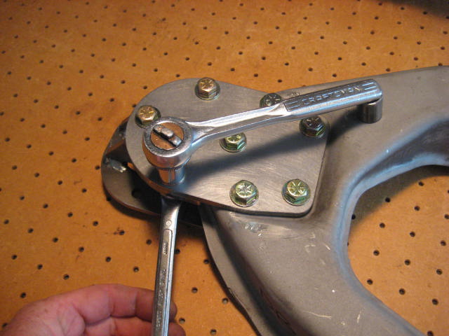
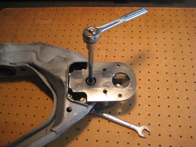
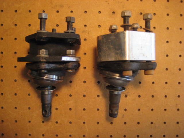
Bolting the UCA Extension Brackets to the Upper control arms is fairly straight forward. First place the washers and bolts onto the top plate.
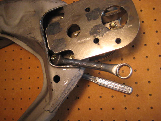
Then position the top plate on the top of the UCA with the bolts fitting through the UCA. Next position the bottom bracket into place from below. Then its just a matter of installing the lock washers and nuts. Then with a combination wrench and ratchet driver with extension and socket torque the nuts and bolts. You will have to flip around the UCA and come at it with different directions with the tools but its not difficult. Here it is being bolted together.
The holes go from 5/16" to 3/8" (.3125 to .3750)
Bolting the UCA Extension Brackets to the Upper control arms is fairly straight forward. First place the washers and bolts onto the top plate.
Then position the top plate on the top of the UCA with the bolts fitting through the UCA. Next position the bottom bracket into place from below. Then its just a matter of installing the lock washers and nuts. Then with a combination wrench and ratchet driver with extension and socket torque the nuts and bolts. You will have to flip around the UCA and come at it with different directions with the tools but its not difficult. Here it is being bolted together.
05-26-2014, 12:17 PM
#7
Registered User
Thread Starter
No, I am not planning on cutting up the unmodified "good" UCA cores I receive to be modified to fit BJ Spacers. And the ones I receive that have been modified, the "bad" ones, the damage has been done. The bad ones are only good for harvesting parts and scrap. The hacked up UCA shell is scrap metal.
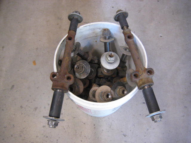
If anyone is interested, here is the harvesting procedure. First off I obtain a set of suitable cores, either from a core return or a local salvage yard. The later is nice because I can be selective and only purchase the ones in excellent condition. Usually from a late model 3.0 V6 "Soccer Mom" 4 Runner taken out of commission because of a blown head gasket. For some reason people find this is too costly to repair and it probably is when the shop bends you over with a $2k or more quote for the repair.
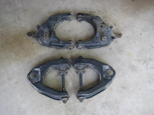
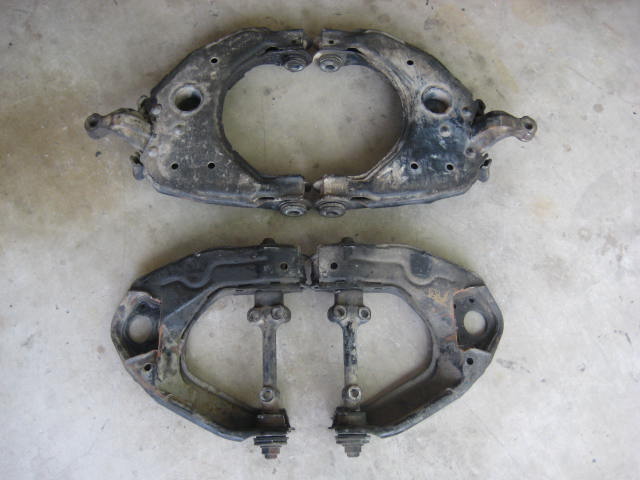
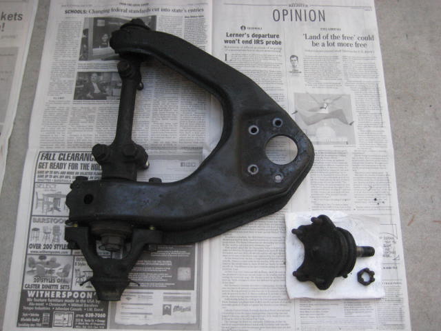
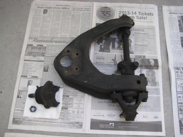
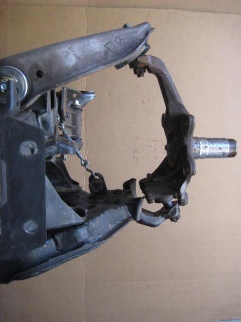
Here is a complete set of cores and the associated parts.
I like to get all the associated parts if I can, especially the late model V6 Torque Arms. Torque Arms are the bracket connecting the Torsion Bar to the UCA. 4 cylinder Torque arms cannot handle aftermarket Torsion Bars and should be replaced for the beefier V6 ones.
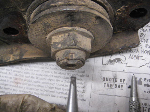
Then I start disassembling. The cross shaft nuts are the first part that can be tricky. I shaped three nail sets to work as progressively sized chisels to un-stake the crown of the nut. It is a good idea to do this carefully because not doing it properly will cause you to strip the threads on the cross shafts.

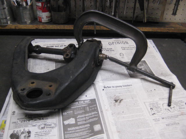
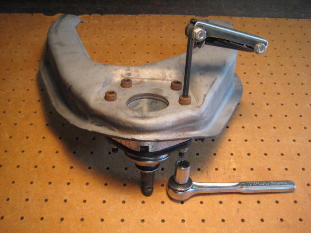
Next, I place the UCA in a vice as shown.
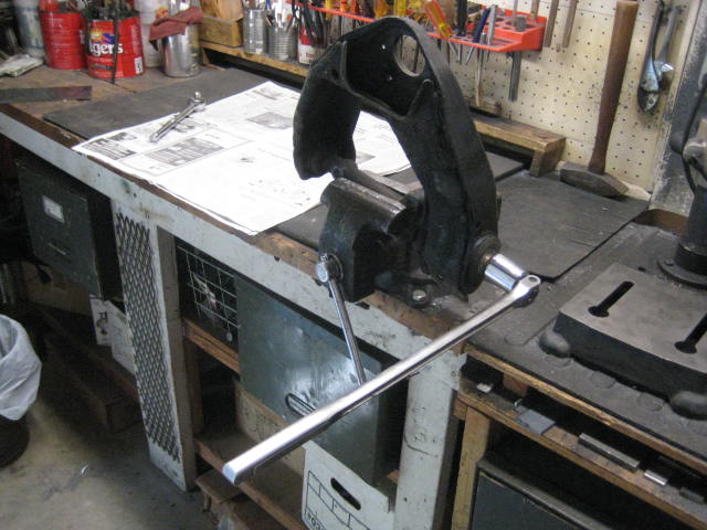
It takes a breaker bar, 1-1/6" socket, and sometimes a cheater pipe to loosen the nuts. The Torque spec to these nuts is quite high. Here is a helpful link to IFS suspension components and associated specifications.
http://personal.utulsa.edu/~nathan-b...27frontsus.pdf
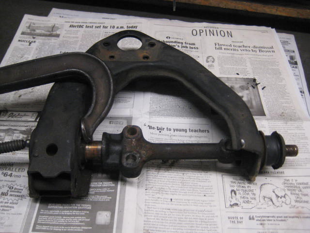
Once the cross shaft nuts have been removed, the cross shaft needs to be pressed out.
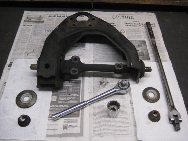
A press is not needed. I have found a large C-clamp, with the fitting removed from the end of the threaded rod, fits into the center bore of the cross shaft. From there its just a matter of tightening the C-clamp to push out the cross shaft.
The front bushing usually comes out with the cross shaft.
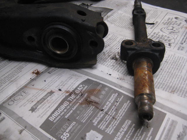
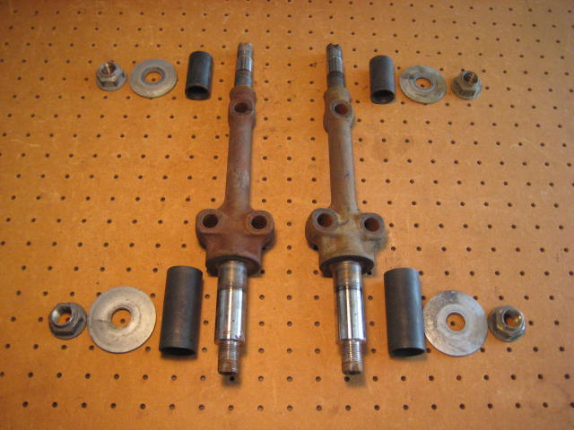
Here is the cross shaft and front bushing removed.
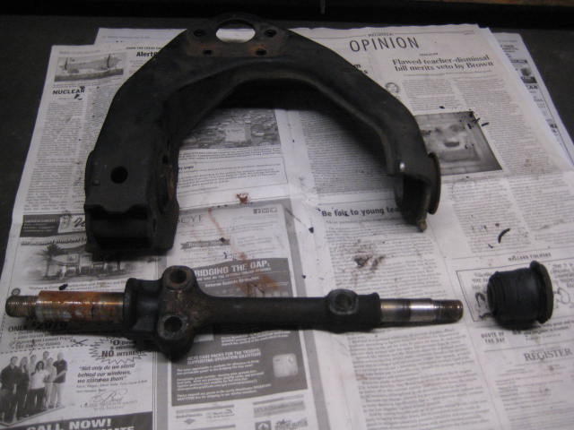
Unfortunately the rear bushing is a bear to remove. It has to be burned out, and that gets messy.
I have buckets of harvested UCA hardware and cross shafts.
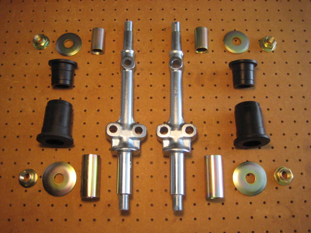
I take the hardware and cross shafts to a vendor to be processed.
The parts are tumbled, sand blasted, and re-plated with zinc. Then they are ready to be re-assembled with new poly bushings.
This process is a ton of work but when it becomes part of a Long Arm Kit it is necessary.
If your just installing BJ Spacers it may not seem to be cost effective to do all this, but converting to poly bushings should be done. Here is why, the factory rubber bushings are not a free floating design. This means as the control arm pivots on the cross shaft the bushing assembly doesn't rotate, it just twist the rubber bushing within the outer steel shell and the inner steel sleeve. This limits travel and puts a stress on the cross.
Don't believe me, take a UCA and lock it in a vice. Now try and rotate the UCA. It is stiff and springy. You could stand on the end of the UCA and use it as a spring board.
The advantage of converting to a poly bushing is it is a free floating assembly. This means the UCA can pivot on the cross shaft without much resistance. This will allow more travel and a smooth non-binding operation.
When you use factory UCAs for Long Travel you are forcing too much rotation in the factory rubber bushing assembly. This may also be the case for BJ Spacers too? This extra rotation will cause the factory rubber to fail and the rubber will chunk apart. The other problem with rubber bushings undergoing extra rotation is it will put a lot of stress on the cross shaft attachment; which can rip the three cross shaft bolts from the frame. Wham Bam thank you Mam!
If anyone is interested, here is the harvesting procedure. First off I obtain a set of suitable cores, either from a core return or a local salvage yard. The later is nice because I can be selective and only purchase the ones in excellent condition. Usually from a late model 3.0 V6 "Soccer Mom" 4 Runner taken out of commission because of a blown head gasket. For some reason people find this is too costly to repair and it probably is when the shop bends you over with a $2k or more quote for the repair.
Here is a complete set of cores and the associated parts.
I like to get all the associated parts if I can, especially the late model V6 Torque Arms. Torque Arms are the bracket connecting the Torsion Bar to the UCA. 4 cylinder Torque arms cannot handle aftermarket Torsion Bars and should be replaced for the beefier V6 ones.
Then I start disassembling. The cross shaft nuts are the first part that can be tricky. I shaped three nail sets to work as progressively sized chisels to un-stake the crown of the nut. It is a good idea to do this carefully because not doing it properly will cause you to strip the threads on the cross shafts.
Next, I place the UCA in a vice as shown.
It takes a breaker bar, 1-1/6" socket, and sometimes a cheater pipe to loosen the nuts. The Torque spec to these nuts is quite high. Here is a helpful link to IFS suspension components and associated specifications.
http://personal.utulsa.edu/~nathan-b...27frontsus.pdf
Once the cross shaft nuts have been removed, the cross shaft needs to be pressed out.
A press is not needed. I have found a large C-clamp, with the fitting removed from the end of the threaded rod, fits into the center bore of the cross shaft. From there its just a matter of tightening the C-clamp to push out the cross shaft.
The front bushing usually comes out with the cross shaft.
Here is the cross shaft and front bushing removed.
Unfortunately the rear bushing is a bear to remove. It has to be burned out, and that gets messy.
I have buckets of harvested UCA hardware and cross shafts.
I take the hardware and cross shafts to a vendor to be processed.
The parts are tumbled, sand blasted, and re-plated with zinc. Then they are ready to be re-assembled with new poly bushings.
This process is a ton of work but when it becomes part of a Long Arm Kit it is necessary.
If your just installing BJ Spacers it may not seem to be cost effective to do all this, but converting to poly bushings should be done. Here is why, the factory rubber bushings are not a free floating design. This means as the control arm pivots on the cross shaft the bushing assembly doesn't rotate, it just twist the rubber bushing within the outer steel shell and the inner steel sleeve. This limits travel and puts a stress on the cross.
Don't believe me, take a UCA and lock it in a vice. Now try and rotate the UCA. It is stiff and springy. You could stand on the end of the UCA and use it as a spring board.
The advantage of converting to a poly bushing is it is a free floating assembly. This means the UCA can pivot on the cross shaft without much resistance. This will allow more travel and a smooth non-binding operation.
When you use factory UCAs for Long Travel you are forcing too much rotation in the factory rubber bushing assembly. This may also be the case for BJ Spacers too? This extra rotation will cause the factory rubber to fail and the rubber will chunk apart. The other problem with rubber bushings undergoing extra rotation is it will put a lot of stress on the cross shaft attachment; which can rip the three cross shaft bolts from the frame. Wham Bam thank you Mam!
Trending Topics
05-27-2014, 02:06 PM
#8
Registered User
Thread Starter
If you have read this far into this thread, good for you! I have explained some similarities and some differences between BJ Spacers and UCA Extension Brackets, but keep reading there is more to come. Either component is altering the engineering. The terminology for discussing this can be simplified in three terms, bending, shear, and moment.
The spindle upright exerts all three forces onto the upper ball joint regardless of BJ Spacers, UCA Extension Brackets, or just in stock unmodified form. The UCA then reacts to these forces with the opposite counter force.
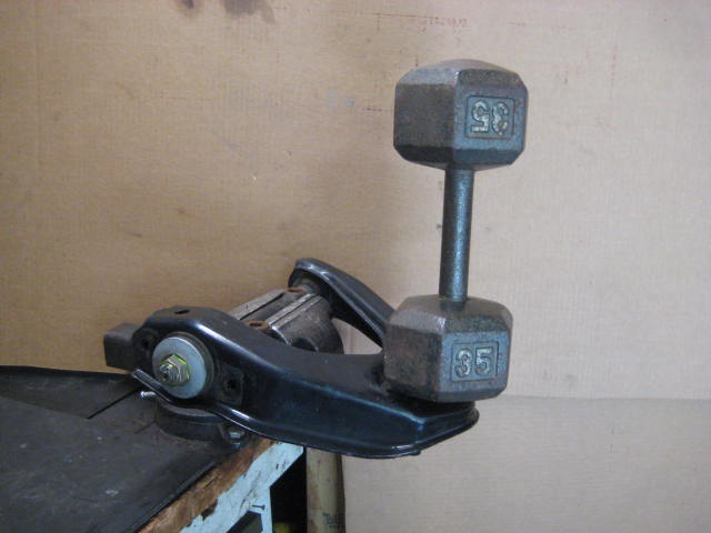
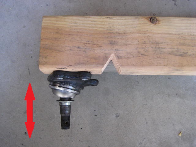
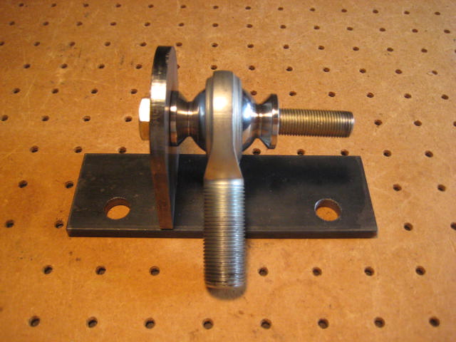
I attached a ball joint to a piece of lumber to explain each force. The lumber represents the UCA.
Bending
Shear
Moment
A vertical force that pushes up or pulls down on the BJ will cause a bending force.
A notch in the lumber will reduce the lumbers ability to resist bending. Cutting away material to make a BJ Spacer fit within the UCA will reduce the UCAs ability to resist bending.
If the UCA is connected to Torsion Bars, the torsional spring load is countering the up force from the spindle with a down force. Think of doing a push up. You can do one of three things, push hard and go up, relax and go down, or balance your exertion to match your body weight and remain stationary. The chest muscles are like the torsion bar springs, the humerus (upper arm bone) is the UCA and the elbow the upper ball joint. The fore arm is like the spindle upright and the wrist the lower ball joint.
For those of you with who have done away with the Torsion Bars and have performed a Coil Over Conversion, the UCA is no longer "reacting" to the vertical forces with a torsional spring load and a such the bending moment is minimal.
If the droop stops are in place when the suspension extends to the limits of down travel, the UCA is subjected to another bending force, but in the opposite direction. If the drop stops have been replaced with limit straps (acting on the LCA) the bending force has been removed from the UCA.
With a coil over conversion and limit strap, the UCA is just going along for a ride. All the UCA is doing is controlling the direction of movement along the arc path, so the bending force in the UCA is greatly reduced.
The BJ Spacer doesn't have an effect on increasing vertical loads, so the factory 22mm torsion bar doesn't need to be upgraded. On the other hand the UCA Extension Bracket lengthens the UCA meaning the 22mm T.B. doesn't have enough spring rate, so upgrading to 25mm aftermarket T.B.s is needed.
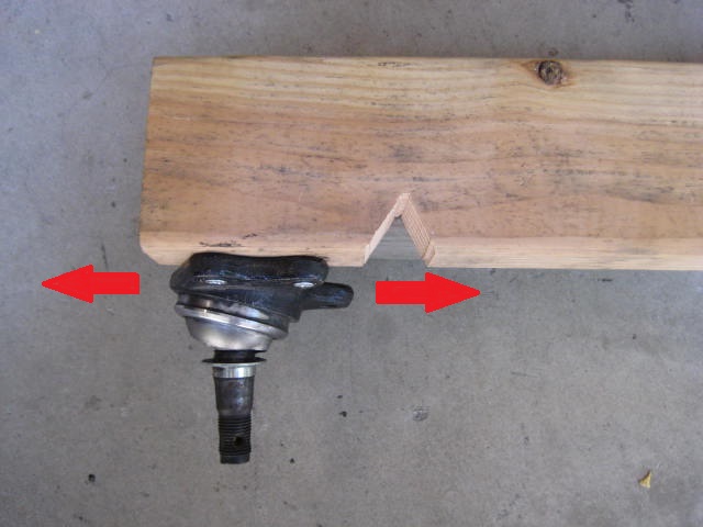
Shear is the tendency produced by loads to deform or fracture a member by sliding one section against another.
In our situation a force pushes the ball joint horizontally in one direction while the lumber pushes back in the opposite. The bolts attaching the BJ to the UCA are the members most likely to be deformed or fractured.
If the vehicle is stationary on level ground the horizontal force is static. The force is mostly acting as an inward push of the tires. If the vehicle is being driven through the whoops, there are all sorts of dynamic shear loads going on in the horizontal plane. Braking and accelerating are forces pushing / pulling in the horizontal plane front to rear. Making turns will push / pull from side to side.
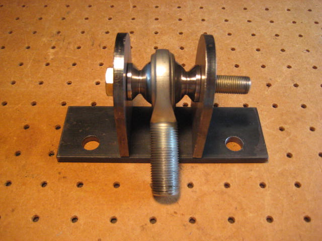
Often we here the term single shear.
Or double shear.
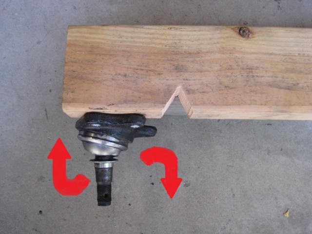
A moment is a movement with a tendency to produce movement about an axis. Take for example the bottle in this picture.
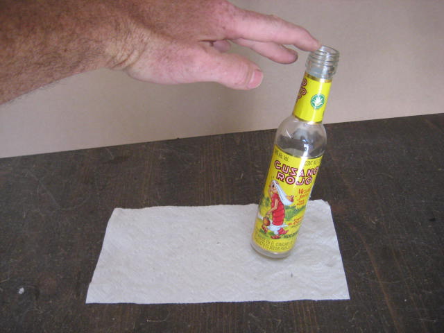
If I push on the bottle with my finger it will rotate on its base and tip over, this is a moment force.
A windmill is a superb example of a moment resistant structure. It was a windy day so this thing was churning like crazy. I would guess the mast was 400 feet tall and the blade diameter was 300 feet in diameter. I walked all around this structure and got close up, what an awh inspiring machine.
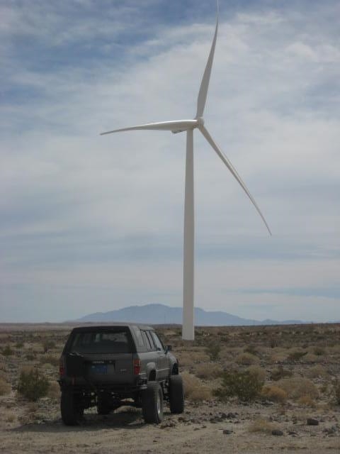
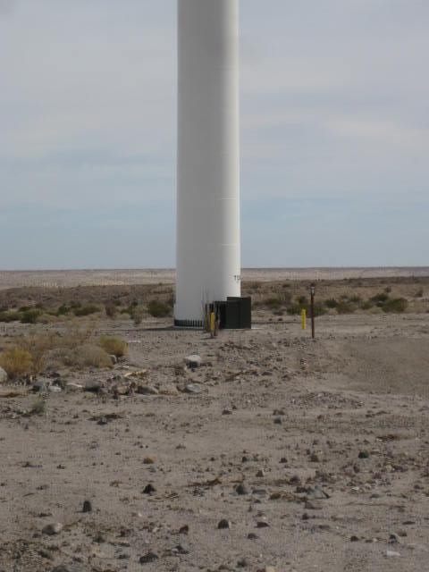
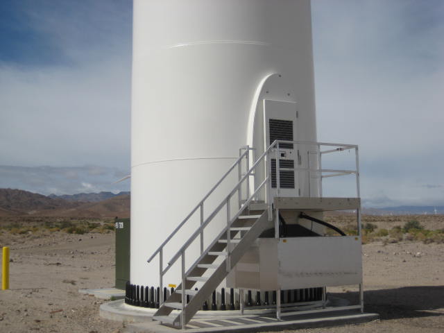
Look at the base of the mast. There are over 100 bolts embedded in a massive underground footing. The moment resistance forces keeping this thing from toppling over in windy conditions must be insane.
Here are some common examples of things we do to our rigs that effect the bending, shear, and especially moment forces.
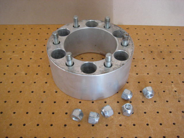
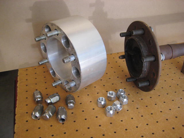
Wheel Adapters
Body Lifts
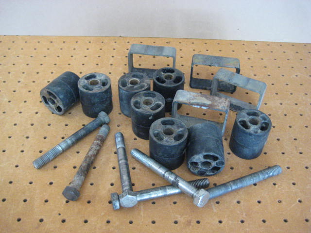
Lift Blocks
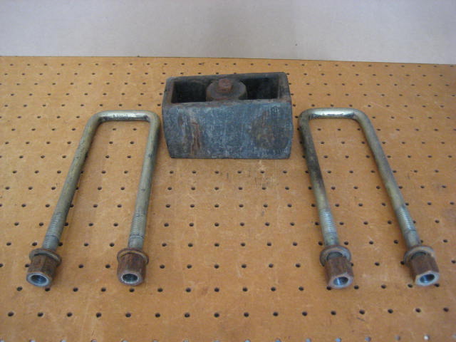
BJ Spacers
The spindle upright exerts all three forces onto the upper ball joint regardless of BJ Spacers, UCA Extension Brackets, or just in stock unmodified form. The UCA then reacts to these forces with the opposite counter force.
I attached a ball joint to a piece of lumber to explain each force. The lumber represents the UCA.
Bending
Shear
Moment
A vertical force that pushes up or pulls down on the BJ will cause a bending force.
A notch in the lumber will reduce the lumbers ability to resist bending. Cutting away material to make a BJ Spacer fit within the UCA will reduce the UCAs ability to resist bending.
If the UCA is connected to Torsion Bars, the torsional spring load is countering the up force from the spindle with a down force. Think of doing a push up. You can do one of three things, push hard and go up, relax and go down, or balance your exertion to match your body weight and remain stationary. The chest muscles are like the torsion bar springs, the humerus (upper arm bone) is the UCA and the elbow the upper ball joint. The fore arm is like the spindle upright and the wrist the lower ball joint.
For those of you with who have done away with the Torsion Bars and have performed a Coil Over Conversion, the UCA is no longer "reacting" to the vertical forces with a torsional spring load and a such the bending moment is minimal.
If the droop stops are in place when the suspension extends to the limits of down travel, the UCA is subjected to another bending force, but in the opposite direction. If the drop stops have been replaced with limit straps (acting on the LCA) the bending force has been removed from the UCA.
With a coil over conversion and limit strap, the UCA is just going along for a ride. All the UCA is doing is controlling the direction of movement along the arc path, so the bending force in the UCA is greatly reduced.
The BJ Spacer doesn't have an effect on increasing vertical loads, so the factory 22mm torsion bar doesn't need to be upgraded. On the other hand the UCA Extension Bracket lengthens the UCA meaning the 22mm T.B. doesn't have enough spring rate, so upgrading to 25mm aftermarket T.B.s is needed.
Shear is the tendency produced by loads to deform or fracture a member by sliding one section against another.
In our situation a force pushes the ball joint horizontally in one direction while the lumber pushes back in the opposite. The bolts attaching the BJ to the UCA are the members most likely to be deformed or fractured.
If the vehicle is stationary on level ground the horizontal force is static. The force is mostly acting as an inward push of the tires. If the vehicle is being driven through the whoops, there are all sorts of dynamic shear loads going on in the horizontal plane. Braking and accelerating are forces pushing / pulling in the horizontal plane front to rear. Making turns will push / pull from side to side.
Often we here the term single shear.
Or double shear.
A moment is a movement with a tendency to produce movement about an axis. Take for example the bottle in this picture.
If I push on the bottle with my finger it will rotate on its base and tip over, this is a moment force.
A windmill is a superb example of a moment resistant structure. It was a windy day so this thing was churning like crazy. I would guess the mast was 400 feet tall and the blade diameter was 300 feet in diameter. I walked all around this structure and got close up, what an awh inspiring machine.
Look at the base of the mast. There are over 100 bolts embedded in a massive underground footing. The moment resistance forces keeping this thing from toppling over in windy conditions must be insane.
Here are some common examples of things we do to our rigs that effect the bending, shear, and especially moment forces.
Wheel Adapters
Body Lifts
Lift Blocks
BJ Spacers
05-27-2014, 02:53 PM
#9
I have been scrapping more and more UCA cores because of BJ Spacer installations lately...
...
Compare my modified UCA to an unmodified stock UCA.

Take the time to do it right! Remove the UCA, do the metal work! If you take it to a shop, tell them what you want! Don't end up with a "Wham bam thank you Mam" install job!
...
Compare my modified UCA to an unmodified stock UCA.
Take the time to do it right! Remove the UCA, do the metal work! If you take it to a shop, tell them what you want! Don't end up with a "Wham bam thank you Mam" install job!

Last edited by RAD4Runner; 05-27-2014 at 09:48 PM.
05-27-2014, 08:47 PM
#10
Registered User
Thread Starter
RAD4Runner, and you can beat a dead horse! I'm on a roll and got a bit more information.
The last post I wrote I went over three engineering terms- bending, shear, and moment. With those principles in mind, lets look at the wheel adapters and evaluate.
First off, I get a lot of strange looks when I tell people I am running 3" wheel adapters on the rear of my 4 Runner and truck. I also run 1.5" wheel adapters on all four corners of my 1985 truck. The 3" adapters have been on the Fordota since 2006. I have never had problems. I beat the heck out of my rigs, lots of jumping, whoops, and pre-running. The Fordota is also putting down way more power than most because its running a Mustang 5.0 EFI V8 motor.
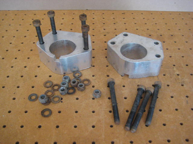
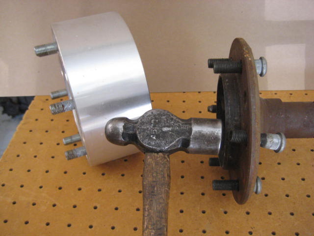
Anyway, the acceptance of wheel adapters is debatable, but a wheel "adapter" is not a wheel "Spacer" Take a look at the following pictures and see a wheel "Adapter" become a wheel "Spacer"
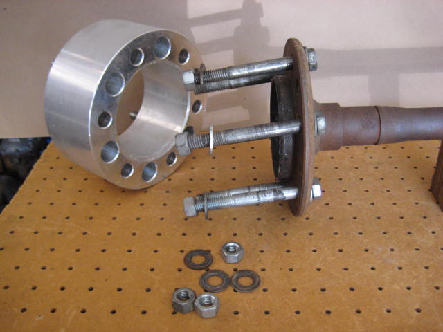
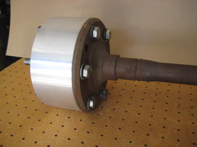
That would be a foolish thing to do. So why is it when a BJ Spacer is installed does this happen?
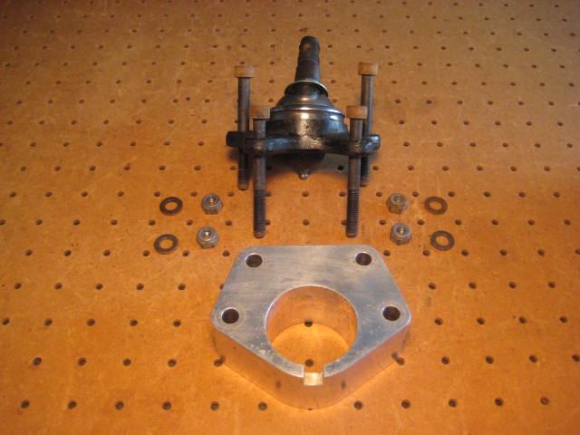
With that in mind, why not build a BJ "Adapter"
It is a good idea, but it you would still have to cut the UCA to make it fit.
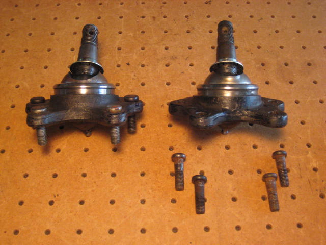
The shear forces would be better handled with BJ Adapters. The adapter uses a set of stubby press fit studs clamping together (2) parts with (1) friction surface between them. The moment is a 1/2" long in the hardware.
The spacer on the other hand, uses long loose fitting bolts, clamping (3) parts together with (2) friction surfaces. The moment is 1-1/2" long in the hardware.
The last post I wrote I went over three engineering terms- bending, shear, and moment. With those principles in mind, lets look at the wheel adapters and evaluate.
First off, I get a lot of strange looks when I tell people I am running 3" wheel adapters on the rear of my 4 Runner and truck. I also run 1.5" wheel adapters on all four corners of my 1985 truck. The 3" adapters have been on the Fordota since 2006. I have never had problems. I beat the heck out of my rigs, lots of jumping, whoops, and pre-running. The Fordota is also putting down way more power than most because its running a Mustang 5.0 EFI V8 motor.
Anyway, the acceptance of wheel adapters is debatable, but a wheel "adapter" is not a wheel "Spacer" Take a look at the following pictures and see a wheel "Adapter" become a wheel "Spacer"
That would be a foolish thing to do. So why is it when a BJ Spacer is installed does this happen?
With that in mind, why not build a BJ "Adapter"
It is a good idea, but it you would still have to cut the UCA to make it fit.
The shear forces would be better handled with BJ Adapters. The adapter uses a set of stubby press fit studs clamping together (2) parts with (1) friction surface between them. The moment is a 1/2" long in the hardware.
The spacer on the other hand, uses long loose fitting bolts, clamping (3) parts together with (2) friction surfaces. The moment is 1-1/2" long in the hardware.
05-30-2014, 06:51 PM
#11
Registered User
Thread Starter
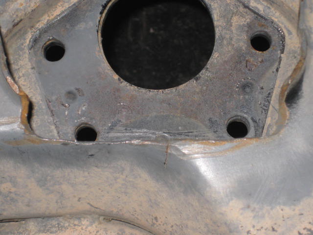
Another look at that UCA that was hacked up to fit the BJ Spacer.
I attempted to re-attached the BJ Spacer in the manner I received it. But, the bolts didn't fit through the (4) holes as they were deformed. I had to pass a drill bit through the holes to get them round again. I didn't enlarge the holes, just hogged them out to be round. Then I was able to get the parts to fit. So I tightened the hardware.
As I tightened I started to wonder if maybe I had put the bolts in from the wrong side? Bolt heads on top, nuts on bottom? Or Nuts on top bolt heads on bottom?
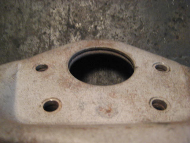
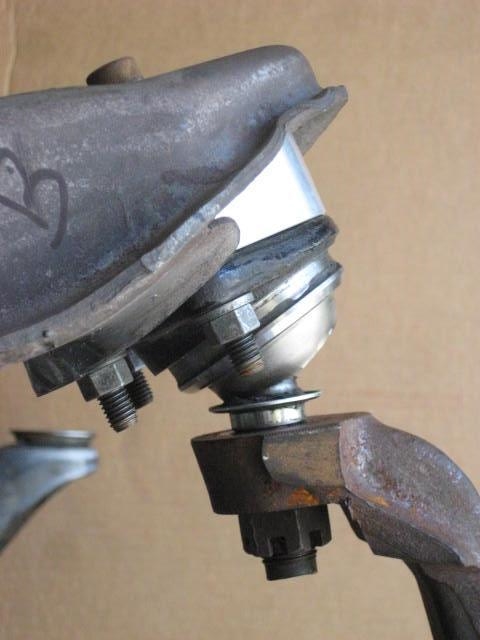
So I took it apart and looked at the top. The small allen bolt head fit perfectly in the deformations. I thought why no washers? As I looked closer I discovered the deformation was more extensive than I thought.
In fact, I observed that the spacer and the UCA base plate mating surfaces wouldn't sit flush.
My guess is there was a moment force acting on the BJ Spacer at the ball joint mating surface. This force rotated the nose of the UCA up (at the outermost (2) bolts) and the back half down (at the (2) bolts further in). This would also cause a bending force at the area along the crack (a tension force).
To get the dynamics of this action to work the UCA would need to be a full droop, the ball joint hyper extended and at bind. Then the spindle would be pushing in and pulling down on the LCA. The simple explanation would be the droop stops were either missing or not properly set.
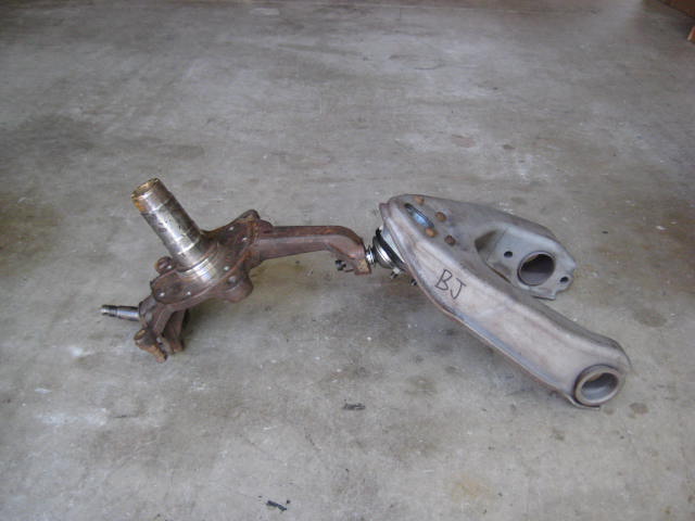
If I were to try and duplicate the damage to the UCA in some sort of testing scenario, here is how it might be mocked up.
Find a big tree and attach one end, the other end to a winch line. Stand clear and pull.
I'm not going to do this as it would be dangerous and when something let go it would be a large heavy projectile object flying through the air. Secondly there would be no way to quantify the force or failure point. If this scenario could be set up in a test lab and I would want to test the A) a standard UCA/BJ/spindle, B) the UCA/BJ Spacer/BJ/spindle, and C) the UCA Extension Bracket/BJ/spindle. Would be cool to see what and how it fails and the force it takes to do it.
Reminder, the ball joint in the above scenario is at full bind. Like hyper extending your knee or elbow. This condition would not happen if droop stops were set correctly. Or even better, limit straps. With stops in place the moment force is reduced, kind of like wearing a knee brace preventing hyper extension.
When you alter the travel range with BJ Spacers, UCA Extension Brackets, low profile bump/droop stops, or what ever it may be, you better make sure to check for binding in the upper and lower ball joints, the outer tie rod end, and the CV axles. If you don't check these items you will have failure points. I'll go over some of this testing next.
I attempted to re-attached the BJ Spacer in the manner I received it. But, the bolts didn't fit through the (4) holes as they were deformed. I had to pass a drill bit through the holes to get them round again. I didn't enlarge the holes, just hogged them out to be round. Then I was able to get the parts to fit. So I tightened the hardware.
As I tightened I started to wonder if maybe I had put the bolts in from the wrong side? Bolt heads on top, nuts on bottom? Or Nuts on top bolt heads on bottom?
So I took it apart and looked at the top. The small allen bolt head fit perfectly in the deformations. I thought why no washers? As I looked closer I discovered the deformation was more extensive than I thought.
In fact, I observed that the spacer and the UCA base plate mating surfaces wouldn't sit flush.
My guess is there was a moment force acting on the BJ Spacer at the ball joint mating surface. This force rotated the nose of the UCA up (at the outermost (2) bolts) and the back half down (at the (2) bolts further in). This would also cause a bending force at the area along the crack (a tension force).
To get the dynamics of this action to work the UCA would need to be a full droop, the ball joint hyper extended and at bind. Then the spindle would be pushing in and pulling down on the LCA. The simple explanation would be the droop stops were either missing or not properly set.
If I were to try and duplicate the damage to the UCA in some sort of testing scenario, here is how it might be mocked up.
Find a big tree and attach one end, the other end to a winch line. Stand clear and pull.
I'm not going to do this as it would be dangerous and when something let go it would be a large heavy projectile object flying through the air. Secondly there would be no way to quantify the force or failure point. If this scenario could be set up in a test lab and I would want to test the A) a standard UCA/BJ/spindle, B) the UCA/BJ Spacer/BJ/spindle, and C) the UCA Extension Bracket/BJ/spindle. Would be cool to see what and how it fails and the force it takes to do it.
Reminder, the ball joint in the above scenario is at full bind. Like hyper extending your knee or elbow. This condition would not happen if droop stops were set correctly. Or even better, limit straps. With stops in place the moment force is reduced, kind of like wearing a knee brace preventing hyper extension.
When you alter the travel range with BJ Spacers, UCA Extension Brackets, low profile bump/droop stops, or what ever it may be, you better make sure to check for binding in the upper and lower ball joints, the outer tie rod end, and the CV axles. If you don't check these items you will have failure points. I'll go over some of this testing next.
05-31-2014, 10:49 AM
#12
Registered User
Thread Starter
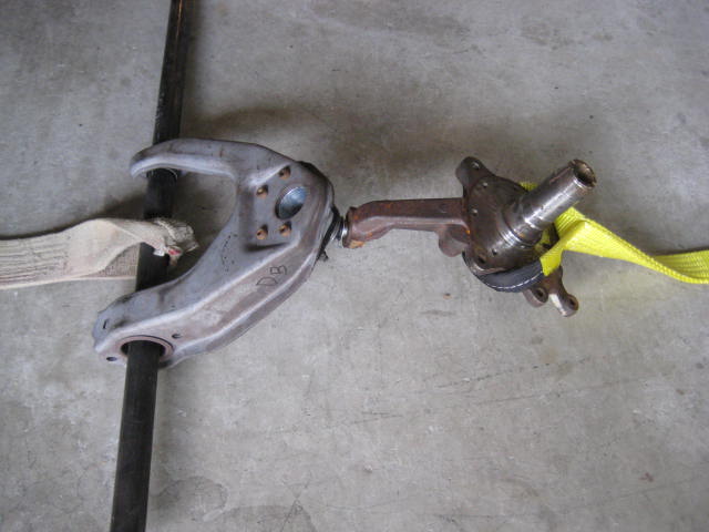
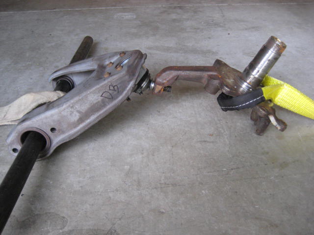
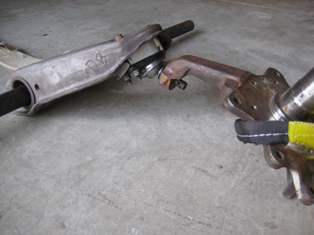
After sleeping on it last night I figured out a better way to test my theory.
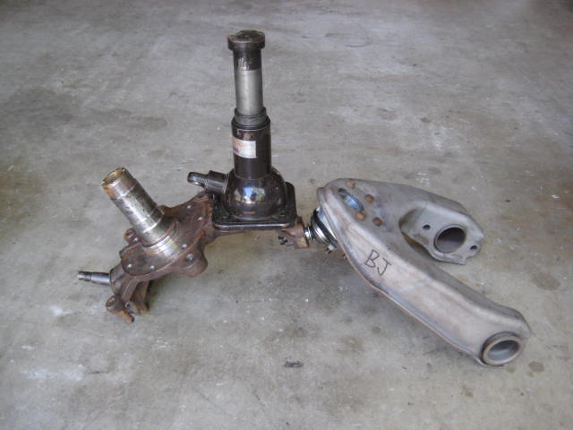
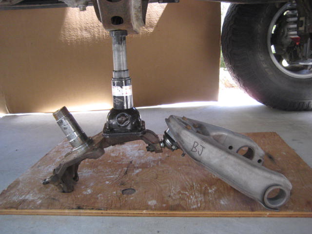
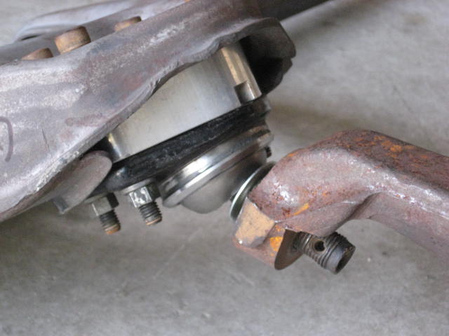
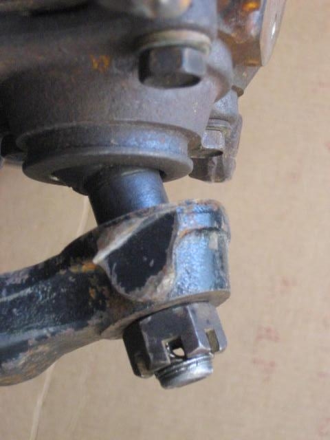
The results were exactly as suspected. The ball joint held up but the slot had some deformation.
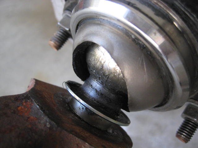
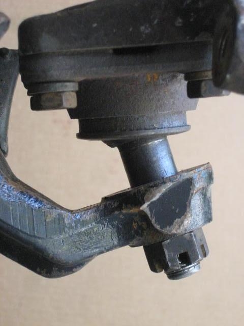
The UCA ball joint mating surface was damaged just like the earlier sample only to a lesser degree.
You can see the deformation to the bolt holes. You can see the bending and separation of the plates forming the UCA ball joint mating surface. The damage was not as severe but this was just a one time load application and not a repeated hammering from the suspension being cycled.
The results were exactly as suspected. The ball joint held up but the slot had some deformation.
The UCA ball joint mating surface was damaged just like the earlier sample only to a lesser degree.
You can see the deformation to the bolt holes. You can see the bending and separation of the plates forming the UCA ball joint mating surface. The damage was not as severe but this was just a one time load application and not a repeated hammering from the suspension being cycled.
06-02-2014, 11:45 PM
#13
Registered User
Thread Starter
I suspect most of you are not wanting to go through the procedure to test what effect altering your Bump and Droop stops will have, so I did it. Which makes sense since I have a front end frame clip for just such test.
I created a spread sheet of the results.
Please note: The data only accounts for upper and lower ball joint operation, it does not take into consideration the steering linkage or CV axle considerations.
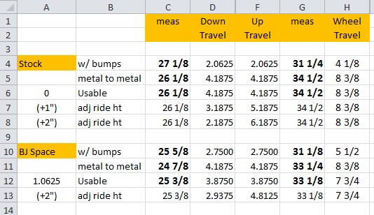
Column C and G (bold numbers) are the actual measurements I took for each of the conditions. I measured from the garage floor to the center line of the spindle snout. The remaining numbers (not in bold face) are calculations derived from the measurements.
Here are some photos I took along the way as I performed the to obtain the measurements.
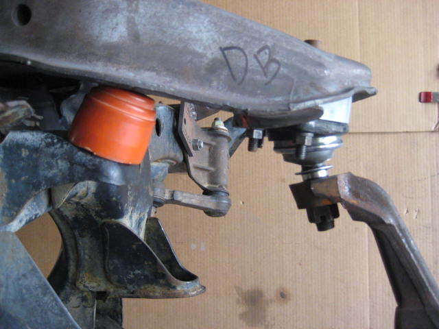
Here is the Stock set up with bump stops removed at full "Up Travel" or stuff.
The lower ball joint rotates operates freely without binding
As does the upper ball joint
The stock set up with droop stops removed at full "Down Travel" or droop.
The lower ball joint rotates operates freely without binding.
As does the upper ball joint.
Here is the set up with BJ Spacers installed, bumpstops removed, at full up travel.
Here is a close up of the LCA and the bump stop bracket. Notice the gap! I was not able to get a metal on metal contact due to ball joints binding.
The upper ball joint is completely locked up
But, the lower ball joint is not maxed out.
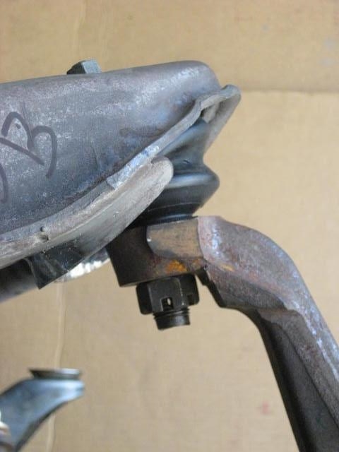
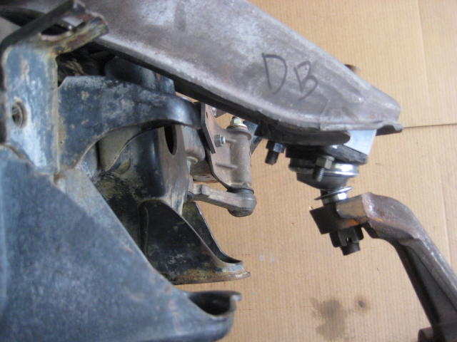
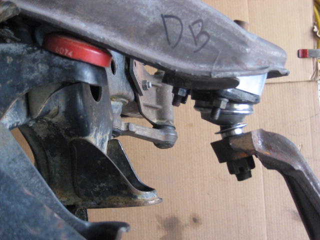
Here is the set up with BJ Spacers installed, droop stops removed, at full down travel.
Here is a close up of the UCA and the droop stop bracket. Notice the gap! I was not able to get a metal on metal contact due to ball joints binding.
The upper ball joint is completely locked up
This time the lower ball joint is also locked up.
And as you turn the spindle to the right or left the BJ flange contacts the LCA.
Back to the spread sheet. Lines 6 and 12 record the "Usable" measurements. To obtain this I dialed back on the up or down travel till the ball joints operated freely. In the case of a stock configuration the metal to metal and useable were the same as the ball joints operated correctly in the metal to metal configuration. In the case of the BJ Spacer the usable wheel travel showed a loss of 5/8" (I12). However if the factory bump and droop stops were intact, wheel travel increased 1-3/8" (I10)
The ride height at the usable measurements for both was averaged (column E6, E12) as zero for stock and +1.0625 for BJ Spacer. This is where the up travel and the down travel were equal (column D6,F6 and D12,F12)
I also included some calculations to show what happens as you adjust the ride height (lines 7,8, and 13) As you increase ride height you gain up travel but loose down travel.
I created a spread sheet of the results.
Please note: The data only accounts for upper and lower ball joint operation, it does not take into consideration the steering linkage or CV axle considerations.
Column C and G (bold numbers) are the actual measurements I took for each of the conditions. I measured from the garage floor to the center line of the spindle snout. The remaining numbers (not in bold face) are calculations derived from the measurements.
Here are some photos I took along the way as I performed the to obtain the measurements.
Here is the Stock set up with bump stops removed at full "Up Travel" or stuff.
The lower ball joint rotates operates freely without binding
As does the upper ball joint
The stock set up with droop stops removed at full "Down Travel" or droop.
The lower ball joint rotates operates freely without binding.
As does the upper ball joint.
Here is the set up with BJ Spacers installed, bumpstops removed, at full up travel.
Here is a close up of the LCA and the bump stop bracket. Notice the gap! I was not able to get a metal on metal contact due to ball joints binding.
The upper ball joint is completely locked up
But, the lower ball joint is not maxed out.
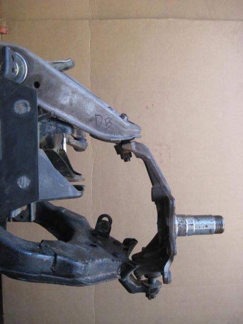
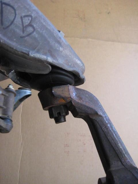
Here is the set up with BJ Spacers installed, droop stops removed, at full down travel.
Here is a close up of the UCA and the droop stop bracket. Notice the gap! I was not able to get a metal on metal contact due to ball joints binding.
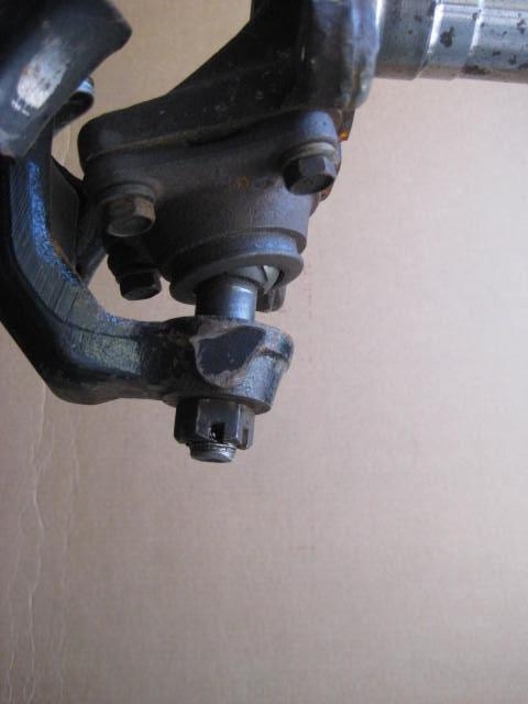
The upper ball joint is completely locked up
This time the lower ball joint is also locked up.
And as you turn the spindle to the right or left the BJ flange contacts the LCA.
Back to the spread sheet. Lines 6 and 12 record the "Usable" measurements. To obtain this I dialed back on the up or down travel till the ball joints operated freely. In the case of a stock configuration the metal to metal and useable were the same as the ball joints operated correctly in the metal to metal configuration. In the case of the BJ Spacer the usable wheel travel showed a loss of 5/8" (I12). However if the factory bump and droop stops were intact, wheel travel increased 1-3/8" (I10)
The ride height at the usable measurements for both was averaged (column E6, E12) as zero for stock and +1.0625 for BJ Spacer. This is where the up travel and the down travel were equal (column D6,F6 and D12,F12)
I also included some calculations to show what happens as you adjust the ride height (lines 7,8, and 13) As you increase ride height you gain up travel but loose down travel.
Last edited by BlazeN8; 06-14-2014 at 09:57 PM.
06-03-2014, 09:16 AM
#14
Registered User
Thread Starter
The conclusion ya'll should be making from reviewing the data is that installing BJ Spacers will alter the usable travel in a way that will compromise the integrity of the upper and lower ball joints. As long as you use the factory bump/droop stops you may not put the BJs into a bind, but that depends on how much the stops compress under actual loading. If you are subjecting the stops to severe use as in hammering through the whoops or jumping it is likely the stops will compress beyond the ball joint working limits.
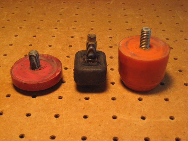
If your following me then you might be thinking about droop stop selection. Here are three examples showing a range of what might be used.
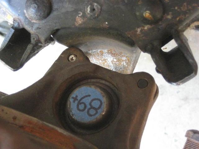
Take a look at the gap between metal to metal contact for a droop condition that results from installing BJ Spacers.
If you were to install low profile droop stops you will be at the bind point even without actual loading that will further compress the stops.
The factory rubber droop stop is constructed from a fairly soft compound, which means it will compress under load. This may or may not put the ball joints into bind, it depends on how severe the load. If you wanted to be on the safe side you should be thinking bigger, thicker droop stops not smaller. In that scenereo this would be the case.
A droop stop limiting the down travel to this degree negates the reason for installing BJ Spacers in the first place? What I am presenting with the spread sheet data is just in terms of the ball joint working limits being maxed out. That doesn't cover the problems with the outer tie rod end being put into bind or the CV Axles be subjected to angles they are not able to handle.
If your following me then you might be thinking about droop stop selection. Here are three examples showing a range of what might be used.
Take a look at the gap between metal to metal contact for a droop condition that results from installing BJ Spacers.
If you were to install low profile droop stops you will be at the bind point even without actual loading that will further compress the stops.
The factory rubber droop stop is constructed from a fairly soft compound, which means it will compress under load. This may or may not put the ball joints into bind, it depends on how severe the load. If you wanted to be on the safe side you should be thinking bigger, thicker droop stops not smaller. In that scenereo this would be the case.
A droop stop limiting the down travel to this degree negates the reason for installing BJ Spacers in the first place? What I am presenting with the spread sheet data is just in terms of the ball joint working limits being maxed out. That doesn't cover the problems with the outer tie rod end being put into bind or the CV Axles be subjected to angles they are not able to handle.
06-03-2014, 09:18 AM
#15
Registered User
iTrader: (1)
Join Date: Nov 2012
Location: Elko NV, at the foot of the Rubys
Posts: 358
Likes: 0
Received 0 Likes
on
0 Posts
Thank you Blazeland, for taking the time to do all this work. Obviously you have a product to sell, but it is great that you are showing the pros and cons of each product, then let the consumer make the final decision based on the numbers, and showing them what NOT to do to be safe.
Just to help my mind clear the fog, in your spread sheet you say the BJ spacers lose usable wheel travel at 1.0625" ride height... is that the ride height you gain with the spacer and not tweaking the torsion bars?
In the end, you only gain wheel travel with a BJ spacer by loosening the torsion bar back to stock ride height after the BJ spacer install? Or am I thinking the wrong way here?
Thank you!
06-03-2014, 09:34 AM
#16
Registered User
Thread Starter
In terms of the spread sheet data, a BJ spacer set to the usable travel limits and equal up travel / down travel it will sit 1.0625" (1-1/16") higher than stock in the same configuration. You would need to crank in the pre-load applied to the Torsion Bars and take measurements till you got the desired height. To get this you would need to do a significant amount of tweaking to the torsion bar adjusting bolt. This would be a trail and error procedure involving lots of floor jack work, measuring and time for settling the suspension.
If you were to make sure you set your droop/bump stop limits properly and dialed in the ride height, BJ Spacers should gain you (1-2") lift and (1") travel. However, to get to this point would require an advanced degree of tuning. Again its not a "Wham Bam Thank You Mam" installation but will require time and effort as well as knowledge. Something a shop will want to be compensated for. It something you can do, great, play around with it.
If you were to make sure you set your droop/bump stop limits properly and dialed in the ride height, BJ Spacers should gain you (1-2") lift and (1") travel. However, to get to this point would require an advanced degree of tuning. Again its not a "Wham Bam Thank You Mam" installation but will require time and effort as well as knowledge. Something a shop will want to be compensated for. It something you can do, great, play around with it.
Last edited by BlazeN8; 06-03-2014 at 09:46 AM.
06-03-2014, 09:48 AM
#17
Registered User
iTrader: (1)
Join Date: Nov 2012
Location: Elko NV, at the foot of the Rubys
Posts: 358
Likes: 0
Received 0 Likes
on
0 Posts
I see what you are saying now, thanks for clearing it up. It is cool to see that your LT kit can double the travel of the front end. Having taken dynamics in college, just a few inches can change your degree of motion quite considerably. I was always under the impression that the stock travel was around 7-8 inches, and that a BJ spacer could help you reach up to 9 inches in travel, just from reading posts around the site. I am glad you have put this data up, you have me leaning towards your weld up kit right now. I bought a BJ spacer kit to temporarily give me time to save up for a LT kit, but I don't want to go through all the work involved if I am not going to be happy with a BJ spacer. Besides the cutting and welding up of the control arms, the work required is identical to getting proper ride height and useable wheel travel. Time to go ponder my options. 
Last edited by chukarhunt; 06-03-2014 at 09:59 AM.
06-03-2014, 10:05 AM
#18
Registered User
Thread Starter
I know it seams like I have a biased opinion as I am motivated to sell my product but honestly its not. My motivation is for the consumer and public safety. I am in a position of knowledge and experience on the mater, and with that I feel morally obliged to share.
I am not saying don't buy this, buy that! I am saying when you modify the suspension be aware of what you are doing. You could be weakening components. You could be changing the geometry in a way to compromise safety, performance, etc.
I just see the consumer being lead in a direction on some products and modifications the they are not experienced with or informed on to understand the ramifications.
06-03-2014, 10:14 AM
#19
Registered User
iTrader: (1)
Join Date: Nov 2012
Location: Elko NV, at the foot of the Rubys
Posts: 358
Likes: 0
Received 0 Likes
on
0 Posts
I know it seams like I have a biased opinion as I am motivated to sell my product but honestly its not. My motivation is for the consumer and public safety. I am in a position of knowledge and experience on the mater, and with that I feel morally obliged to share.
I am not saying don't buy this, buy that! I am saying when you modify the suspension be aware of what you are doing. You could be weakening components. You could be changing the geometry in a way to compromise safety, performance, etc.
I just see the consumer being lead in a direction on some products and modifications the they are not experienced with or informed on to understand the ramifications.
I am not saying don't buy this, buy that! I am saying when you modify the suspension be aware of what you are doing. You could be weakening components. You could be changing the geometry in a way to compromise safety, performance, etc.
I just see the consumer being lead in a direction on some products and modifications the they are not experienced with or informed on to understand the ramifications.
 ). I appreciate you posting this tech, it answers a lot of my questions!
06-03-2014, 12:39 PM
). I appreciate you posting this tech, it answers a lot of my questions!
06-03-2014, 12:39 PM
#20
Registered User
I know it seams like I have a biased opinion as I am motivated to sell my product but honestly its not. My motivation is for the consumer and public safety. I am in a position of knowledge and experience on the mater, and with that I feel morally obliged to share.
I am not saying don't buy this, buy that! I am saying when you modify the suspension be aware of what you are doing. You could be weakening components. You could be changing the geometry in a way to compromise safety, performance, etc.
I just see the consumer being lead in a direction on some products and modifications the they are not experienced with or informed on to understand the ramifications.
I am not saying don't buy this, buy that! I am saying when you modify the suspension be aware of what you are doing. You could be weakening components. You could be changing the geometry in a way to compromise safety, performance, etc.
I just see the consumer being lead in a direction on some products and modifications the they are not experienced with or informed on to understand the ramifications.


