BlazeN8s RanchoHybrid
 05-29-2015, 08:45 PM
#1
Registered User
Thread Starter
BlazeN8s RanchoHybrid
It was 2005 and I had the bright idea of building my own Long Travel kit by combining the 3" Rancho lift kit I had on my 1986 truck with Long Arms. When it came to suspension for the 1986-1995 Toyota 4x4, Downey and Total Chaos were the major players at the time. Downey was using the Rancho UCA mid travel, minus the diff drop bracket. Total Chaos was, and still is using all new UCAs and LCAs that are +3.25" longer. Downey / Rancho kit cycled 11" of travel and TC cycled 12" with 4WD / 13" w/o. With the Downey design, the Rancho diff drop brackets were omitted, and the diff stayed in the stock location. Because there was no diff drop the standard CV axles would bind, so they were replaced with slip yoke CVs. With TC the longer control arms created the increased travel. With TC, longer CVs from a T-100 were used to make up the needed length difference.
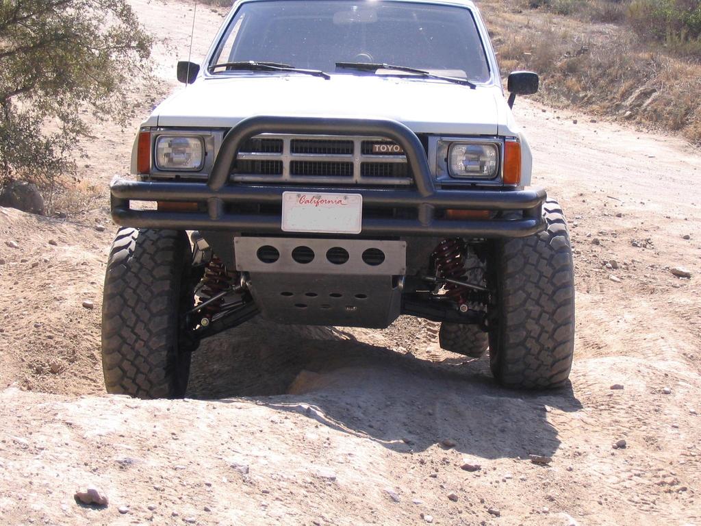
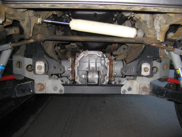
Downey is gone and the Rancho mid travel is discontinued, but once in a while you will see a rig sporting the kit. Here is what it looked like.
I had the bright idea of lengthening control arms to plug into the Rancho kit. I first just bolted a plate onto the UCA and then cut and lengthened a stock LCA. It was really crude but enough to bolt onto my truck to explore the geometry. I cycled the suspension and found a decent increase in travel, I think it was around 13" Next I doubled up the lengthening plate and added a spacer to drop down the ball joint.
This got me into the 15" range. At the time I didn't realize it but I had just stumbled on the UCA Extension Bracket concept. I had broken a set of Rancho UCAs years before pre-running the Baja 250 in San Felipe so I didn't think it was a good idea to use the UCA Extension Bracket for anything more than mock up to build a new UCA. The other reason I was wanting a new UCA is to do a coil over conversion that could not be done within the pocket of a Rancho UCA for clearance issues. And lastly, Torsion Bars and the way the Rancho UCA rotates inboard on the frame doesn't Jive. I took my mock up arms to Franks Fab Shop in Costa Mesa CA and had him build me a new set of UCAs.

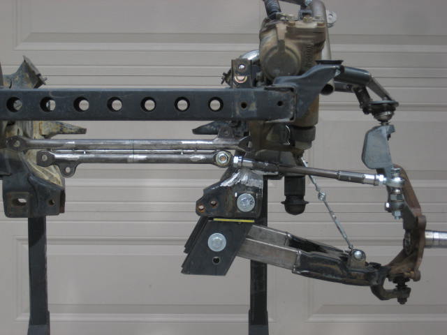
To complete the kit I cut the inner tie rod ends and lengthened them. Here is the hybrid kit.
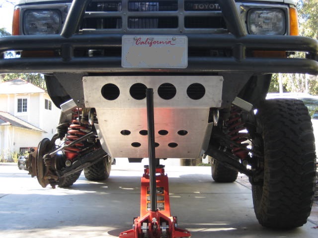
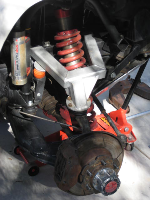
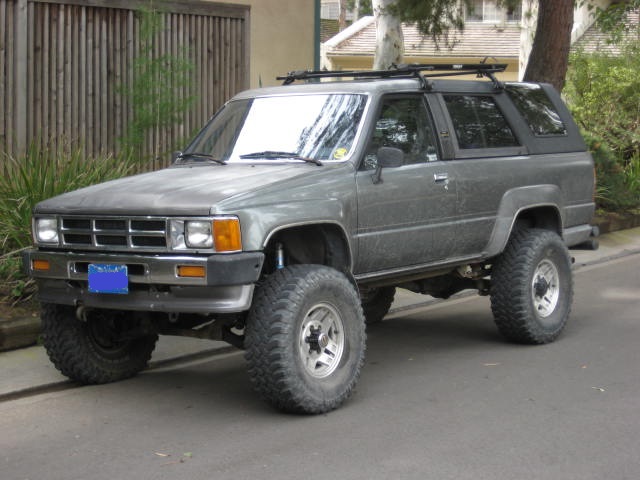
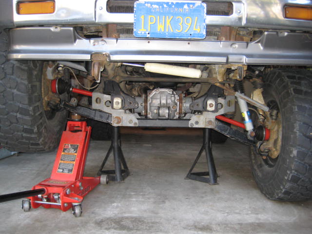
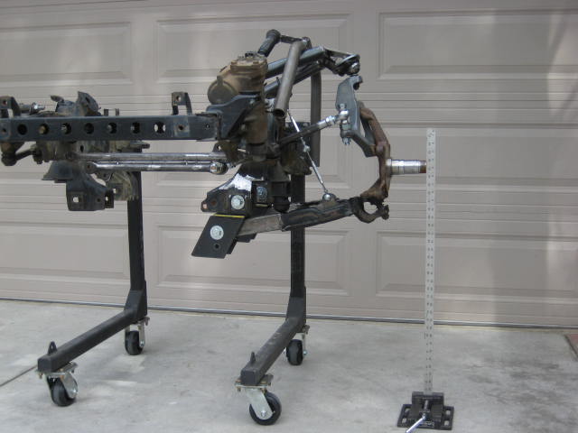
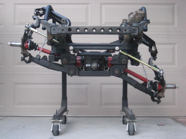
I installed the new components on my 1986 truck and aligned as best as I could in the garage. I then drove down to my local Firestone dealer and had the alignment done professionally. First times a charm because it came out within specifications. Here is the truck with the suspension at full droop.
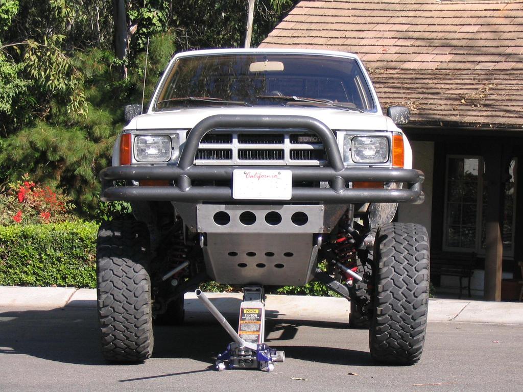
I didn't have CVs so I blocked off the spindle and ran it in 2WD mode for a while. The upper and lower ball joints and outer tie rod ends were binding at 15" so a added some thick poly droop stops and limited the down travel to around 14" When I finally got some T-100 CVs and installed them it was obvious they wouldn't work at 14" without the Rancho diff drop brackets so I kept the brackets in place.
Even with the diff dropped 1-1/2" the CVs would bind. It was the plunge in the inner tripod that bottomed out. Because the diff was lower, the geometry was changed, the CVs now pivoted differently than the pivots of the lower control arms. So I had to limit the travel to 13" to prevent CV binding. The aluminum skid up front sort of hid and protected the diff assembly but it still hung down too low. On the trail it practically graded the crown of the road as the suspension cycled in the whoops.
13" with 4WD is still a decent package. I ran this setup till 2007 when I stuffed the front end into a ditch and bent one of the UCAs. Here is one of the few picture of the original set up I could find.
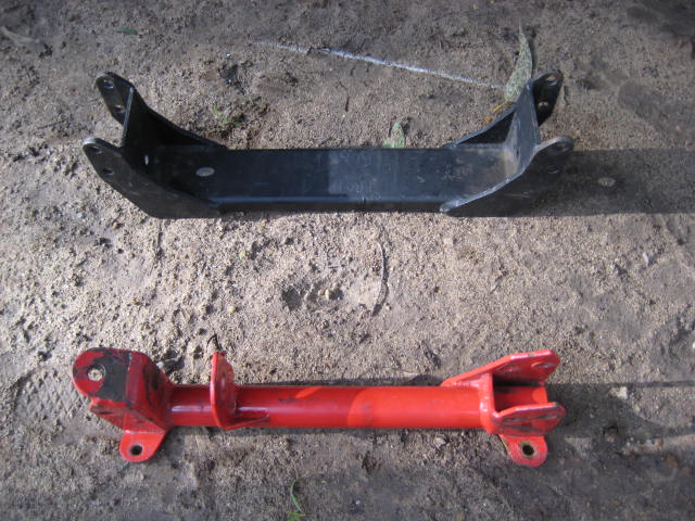
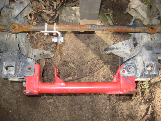
I decided to rebuild but beef it up this time. I used 2x2 1/4" wall square tube. I also increased the LCA / UCA lengths to +4" over to correct the CV plunge bind issue.
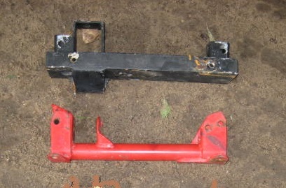
I also built a new front and rear cross member that didn't hang down 3" like the Rancho design. The new ones I built still lowered the diff assembly 1-1/2" but the new configuration gained about 1-1/2" of running ground clearance at the front cross member and at the rear it was nearly flush. I also trimmed the front aluminum skid plate accordingly.
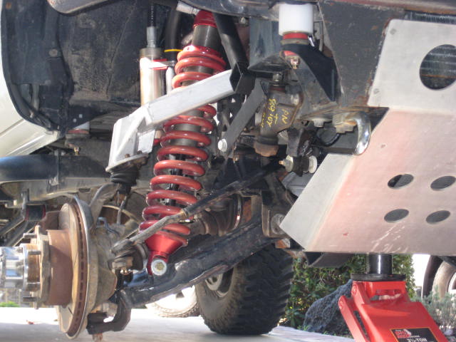
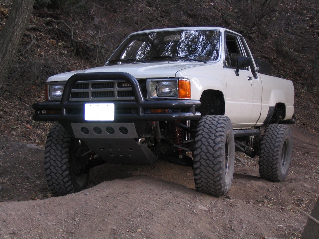
Soon after I stepped up to 35" tires.
The truck had a 2" body lift but the tires rubbed the firewall seam and bottom edge of the fenders. I hammered the seam flat and trimmed the fender to remedy.
In 2009 I took off the Rancho Hybrid kit. I had a 1986 4 Runner and it had the Blazeland Long Arm kit that worked equally well. It had an inch less travel but I didn't really notice the difference.
The other thing about the Rancho Hybrid is that low riding front diff would just drag too much. I'd been selling the Blazeland Long Arms for a couple of years at this point so I decided to install that kit on the truck as well. I figured it was a better to promote things if I had the LA kit on the both rigs. The 4 Runner was the Torsion Bar platform and the truck was the coil over conversion kit w/ shock hoops.
There are some carry over features from the Rancho Hybrid kit on my Mega Travel prototype. You can do some searches here on YT to find out more. Anyhow here is a photo of the Mega Travel.
Downey is gone and the Rancho mid travel is discontinued, but once in a while you will see a rig sporting the kit. Here is what it looked like.
I had the bright idea of lengthening control arms to plug into the Rancho kit. I first just bolted a plate onto the UCA and then cut and lengthened a stock LCA. It was really crude but enough to bolt onto my truck to explore the geometry. I cycled the suspension and found a decent increase in travel, I think it was around 13" Next I doubled up the lengthening plate and added a spacer to drop down the ball joint.
This got me into the 15" range. At the time I didn't realize it but I had just stumbled on the UCA Extension Bracket concept. I had broken a set of Rancho UCAs years before pre-running the Baja 250 in San Felipe so I didn't think it was a good idea to use the UCA Extension Bracket for anything more than mock up to build a new UCA. The other reason I was wanting a new UCA is to do a coil over conversion that could not be done within the pocket of a Rancho UCA for clearance issues. And lastly, Torsion Bars and the way the Rancho UCA rotates inboard on the frame doesn't Jive. I took my mock up arms to Franks Fab Shop in Costa Mesa CA and had him build me a new set of UCAs.
To complete the kit I cut the inner tie rod ends and lengthened them. Here is the hybrid kit.
I installed the new components on my 1986 truck and aligned as best as I could in the garage. I then drove down to my local Firestone dealer and had the alignment done professionally. First times a charm because it came out within specifications. Here is the truck with the suspension at full droop.
I didn't have CVs so I blocked off the spindle and ran it in 2WD mode for a while. The upper and lower ball joints and outer tie rod ends were binding at 15" so a added some thick poly droop stops and limited the down travel to around 14" When I finally got some T-100 CVs and installed them it was obvious they wouldn't work at 14" without the Rancho diff drop brackets so I kept the brackets in place.
Even with the diff dropped 1-1/2" the CVs would bind. It was the plunge in the inner tripod that bottomed out. Because the diff was lower, the geometry was changed, the CVs now pivoted differently than the pivots of the lower control arms. So I had to limit the travel to 13" to prevent CV binding. The aluminum skid up front sort of hid and protected the diff assembly but it still hung down too low. On the trail it practically graded the crown of the road as the suspension cycled in the whoops.
13" with 4WD is still a decent package. I ran this setup till 2007 when I stuffed the front end into a ditch and bent one of the UCAs. Here is one of the few picture of the original set up I could find.
I decided to rebuild but beef it up this time. I used 2x2 1/4" wall square tube. I also increased the LCA / UCA lengths to +4" over to correct the CV plunge bind issue.
I also built a new front and rear cross member that didn't hang down 3" like the Rancho design. The new ones I built still lowered the diff assembly 1-1/2" but the new configuration gained about 1-1/2" of running ground clearance at the front cross member and at the rear it was nearly flush. I also trimmed the front aluminum skid plate accordingly.
Soon after I stepped up to 35" tires.
The truck had a 2" body lift but the tires rubbed the firewall seam and bottom edge of the fenders. I hammered the seam flat and trimmed the fender to remedy.
In 2009 I took off the Rancho Hybrid kit. I had a 1986 4 Runner and it had the Blazeland Long Arm kit that worked equally well. It had an inch less travel but I didn't really notice the difference.
The other thing about the Rancho Hybrid is that low riding front diff would just drag too much. I'd been selling the Blazeland Long Arms for a couple of years at this point so I decided to install that kit on the truck as well. I figured it was a better to promote things if I had the LA kit on the both rigs. The 4 Runner was the Torsion Bar platform and the truck was the coil over conversion kit w/ shock hoops.
There are some carry over features from the Rancho Hybrid kit on my Mega Travel prototype. You can do some searches here on YT to find out more. Anyhow here is a photo of the Mega Travel.
 06-04-2015, 06:57 PM
#2
Registered User
Thread Starter
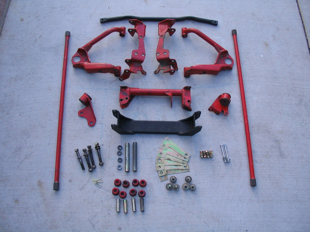
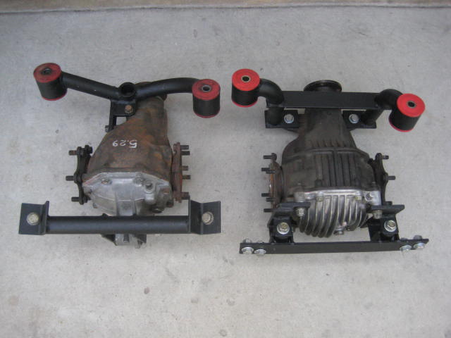
A recent customer pulled a Rancho kit off his rig and installed a Blazeland Long Arm kit. I ended up with the old Rancho kit. Here are a few photos.
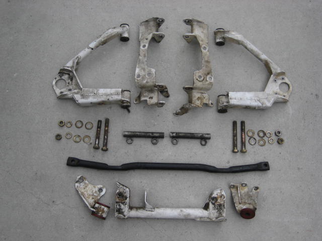
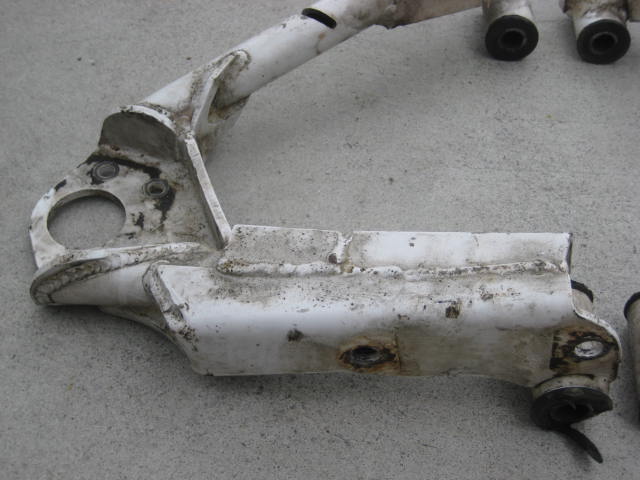
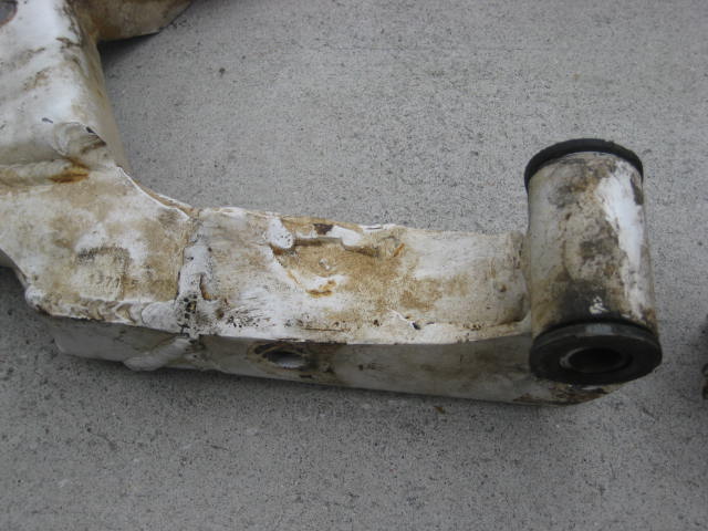
Overall the kit was intact but worn out and beat up. Some where along the way it was powder coated white. The bushings were dry and chewed up. Some hardware, shims, sleeves etc. were missing or not used. The guy said he gave me everything except the factory bits he needed to install with the long arm kit. If that were the case the other guy had installed it incorrectly as some important parts were missing.
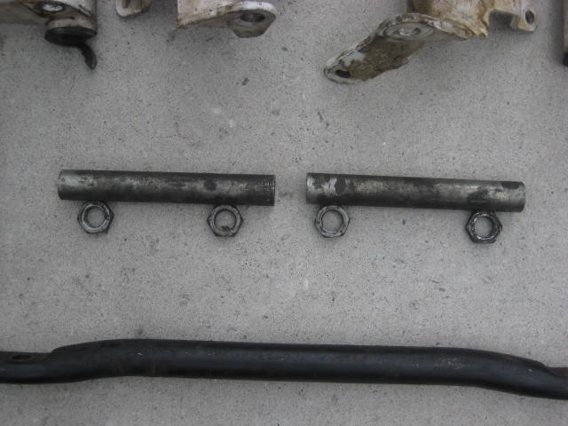
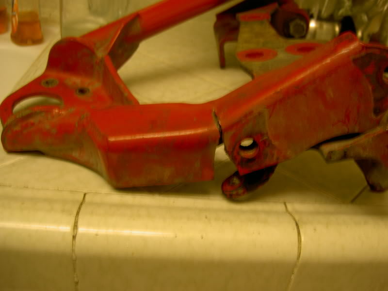
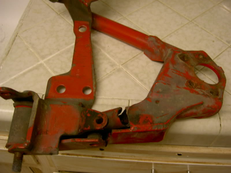
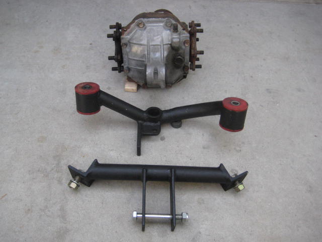
The centerlink and differential drop brackets were in great shape, just a bit dirty.
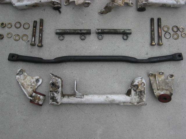
The Tie Rod Adjusting Sleeves were also in good shape and could be refurbished easily.
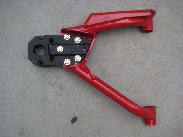
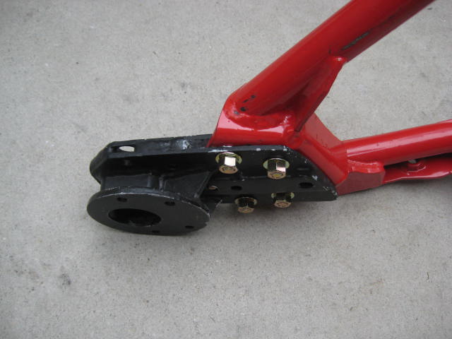
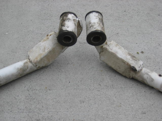
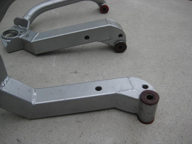
The UCA pivot relocation Brackets were in good shape but the UCAs were thrashed.
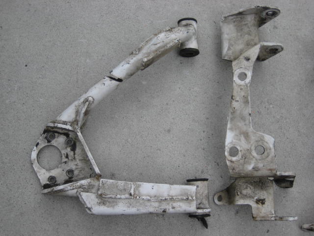
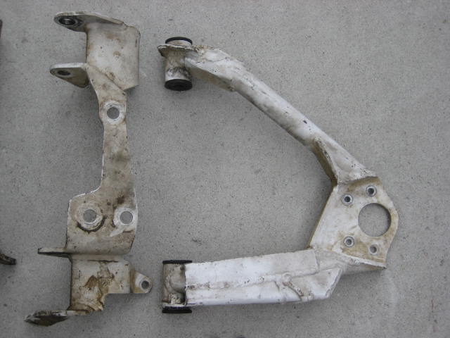
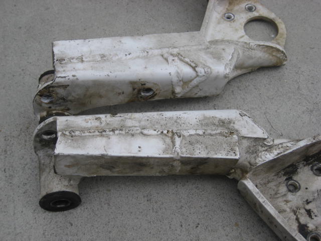
The Rancho UCAs were prone to failure. The RH UCA looks to be the one that had failed in the typical fashion. The UCA was repaired crudely with plate, angle, and channel scrap but structurally the repair was solid. The LH side may not have failed but it was repaired to match the RH side repairs.
Here is the LH top.
LH Bottom
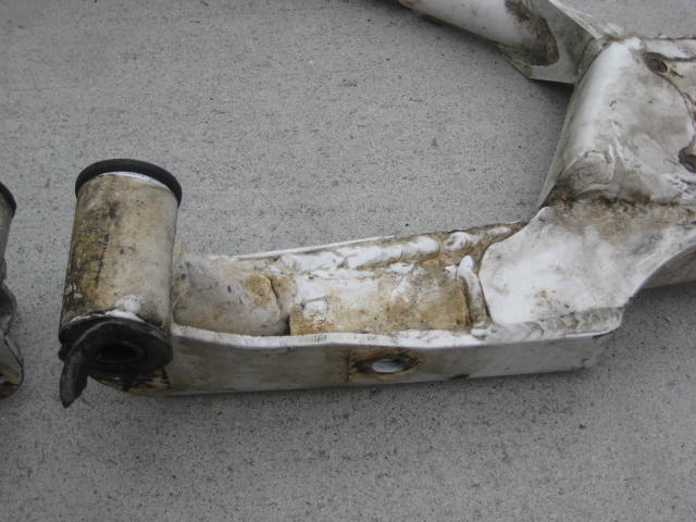
RH top
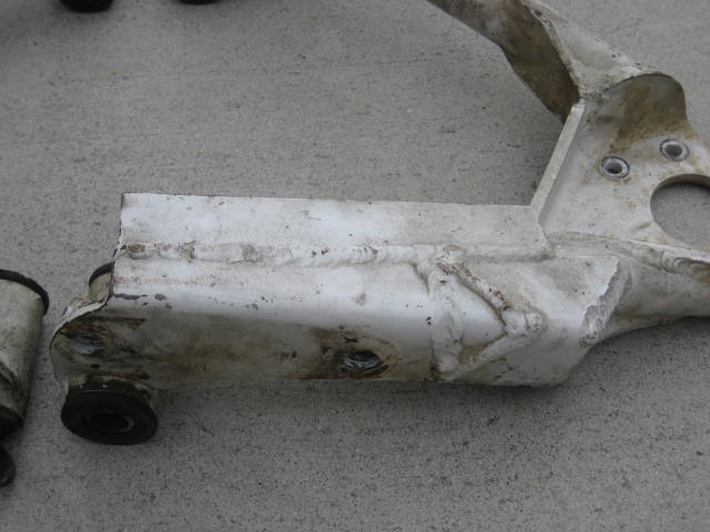
RH bottom

The front leg part of the UCA was also beefed up with a channel.
Overall the kit was intact but worn out and beat up. Some where along the way it was powder coated white. The bushings were dry and chewed up. Some hardware, shims, sleeves etc. were missing or not used. The guy said he gave me everything except the factory bits he needed to install with the long arm kit. If that were the case the other guy had installed it incorrectly as some important parts were missing.
The centerlink and differential drop brackets were in great shape, just a bit dirty.
The Tie Rod Adjusting Sleeves were also in good shape and could be refurbished easily.
The UCA pivot relocation Brackets were in good shape but the UCAs were thrashed.
The Rancho UCAs were prone to failure. The RH UCA looks to be the one that had failed in the typical fashion. The UCA was repaired crudely with plate, angle, and channel scrap but structurally the repair was solid. The LH side may not have failed but it was repaired to match the RH side repairs.
Here is the LH top.
LH Bottom
RH top
RH bottom
The front leg part of the UCA was also beefed up with a channel.
Last edited by BlazeN8; 06-07-2015 at 07:32 PM.
06-05-2015, 11:25 AM
#3
Registered User
Thread Starter
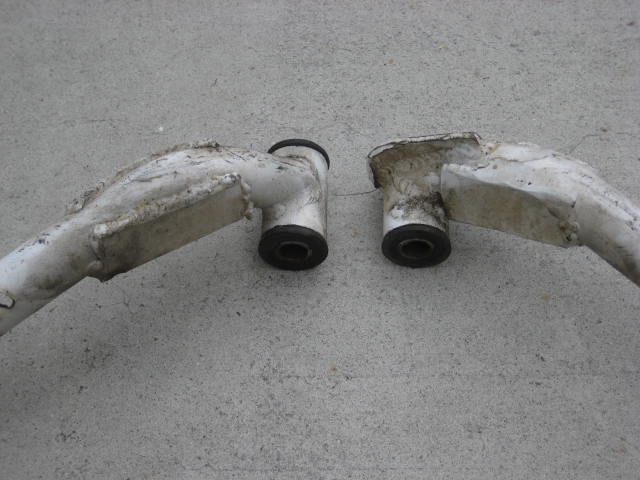
The typical failure point to the Rancho UCA is on the rear leg part of the UCA. I found a couple of threads here on YotaTech where guys had Rancho UCA failure. If you want to read about them do a key word search and type in "Ranchoda" to find the threads. If readers out there know of other good threads concerning Rancho kit post a comment and mention "Ranchoda" so we all can find it too.
Anyway, here are a couple of photos I borrowed from one of the threads where the control arm fails. This is exactly what mine looked like when it happened to me in San Felipe.
The tube work on the Rancho UCAs are 1-1/4" O.D. with a .120 wall. At the failure point the top and side has a 1-1/4 x 1-3/4 angle with a 3/16" wall. But the bottom and inside is not boxed. The cross sectional area at this location is not sufficient. This is where the Torsion Bar Torque Arm connects to the UCA so there is a tremendous bending moment force as the UCA pushes up and the torque arm resist by pushing down. The force is compounded by the Torsion Bar spring load pushing the UCA down onto the Droop Stop. I suspect there is metal fatigue as each time the suspension cycles and contacts the droop stop the moment force switches from bending up to bending down.
If you look at the repair job on the white UCAs you can see he added a second angle wrapping over the inner side. And he added material to the bottom boxing in the tube on all four sides. Like I mentioned earlier crude repair but structurally it was sufficient.
When I built the first hybrid plug in UCA
I used 1.5" .120 wall tube, but it wasn't DOM as some how materials got mixed. I found out later, after it failed.
Here is an explanation I found helpful.
"DOM is actually not a type of tubing, but a process that is applied to tubing after it is initially constructed. It is Drawn Over a Mandrel...which "cold works" it, giving it more exact dimensions relative to the inside and outside diameters, a smoother finish, and better alignment of the crystal lattice structure. Although it is almost always referred to as a SEAMLESS tube, technically it is NOT seamless tubing, and it started life as some sort of EW (electric welded) tubing. During the manufacturing process, the weld line becomes nearly undetectable, thus it is referred to as SEAMLESS. It is considered a high strength, high quality tube, and is normally constructed from SAE 1020 or 1026 steel. DOM is commonly used in the manufacturing of race cars and motorcycle frames"
In my case what got mixed in as the arms were constructed was tube, but the material was a lower grade.
The cross sectional area of my 1-1/2" UCAs was actually less than the Rancho design 1-1/4" because Rancho added the angle. I figured I was okay because the moment force created by the torsion bar was removed due to the coil spring conversion. This design held of for a few desert trips but stuffing the front end of the truck into a ditch ended up bending the UCA. I still have the tube ends in a box of tube remnants.
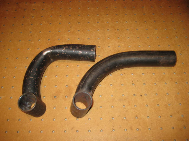
The tube had also been weekend because it had been shaped in a tube bender with a fairly tight radius and bend angle. As the tube is pulled through the bender the outside of the radius stretches and becomes thinner. Once a tube is bent it is much easier to continue the bend.
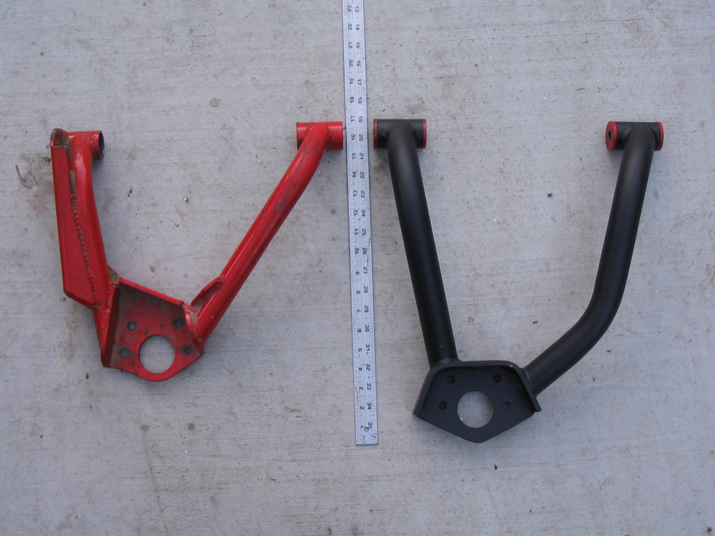
I repaired these UCAs and made a design change to the rear leg of the arm. This time I used 2" square tube with 1/8" wall. I also incorporated the ability to attach the Torque Arms for a Torsion Bar option.
The Torsion Bar option ended up being a dud as the spring rate options of available Torsion Bars is limited and the UCA pivot relocation means the Torsion Bar no longer rotate on the center line of the cross shaft. The result is as the UCA pivots the Torsion bar not only rotated but also moved up and down.
Next up was the UCA constructed of of 2x2 square tube with 1/4" wall. Deleted the Torsion Bar option and back to Coil Over Conversion. These arms were also +4" over to correct the CV axle bind issues. These UCAs were probably overkill with 2" square tube and weighed about 30 lbs. These arms served me well for years but were retired for the above mentioned reasons.
Current UCA in Mega Travel uses schedule 40 structural pipe with a 1-5/8" OD and a .140 wall. This UCA is not bent in a pipe bender but is straight pipe with miter cut sections and tube elbows with internal slugs.
I envisioned selling an upgrade option to work with my Long Arm LCAs. This is still something I am playing around with but a major problem is this option does not work with the limitations of the T-100 CV Axle, so 12" of wheel travel is you get with 4WD. If you wanted to build a 2WD Pre-Runner you can get this set up to cycle 14" of travel M2M (metal to metal, bump and droop stops removed) Upper BJ needs to be clearance modified, lower BJ is maxed out. Steering linkage is complicated. I'll go over the solutions and the Mega Travel in the next series of post, so subscribe to this thread and stay tuned.
Anyway, here are a couple of photos I borrowed from one of the threads where the control arm fails. This is exactly what mine looked like when it happened to me in San Felipe.
The tube work on the Rancho UCAs are 1-1/4" O.D. with a .120 wall. At the failure point the top and side has a 1-1/4 x 1-3/4 angle with a 3/16" wall. But the bottom and inside is not boxed. The cross sectional area at this location is not sufficient. This is where the Torsion Bar Torque Arm connects to the UCA so there is a tremendous bending moment force as the UCA pushes up and the torque arm resist by pushing down. The force is compounded by the Torsion Bar spring load pushing the UCA down onto the Droop Stop. I suspect there is metal fatigue as each time the suspension cycles and contacts the droop stop the moment force switches from bending up to bending down.
If you look at the repair job on the white UCAs you can see he added a second angle wrapping over the inner side. And he added material to the bottom boxing in the tube on all four sides. Like I mentioned earlier crude repair but structurally it was sufficient.
When I built the first hybrid plug in UCA
I used 1.5" .120 wall tube, but it wasn't DOM as some how materials got mixed. I found out later, after it failed.
Here is an explanation I found helpful.
"DOM is actually not a type of tubing, but a process that is applied to tubing after it is initially constructed. It is Drawn Over a Mandrel...which "cold works" it, giving it more exact dimensions relative to the inside and outside diameters, a smoother finish, and better alignment of the crystal lattice structure. Although it is almost always referred to as a SEAMLESS tube, technically it is NOT seamless tubing, and it started life as some sort of EW (electric welded) tubing. During the manufacturing process, the weld line becomes nearly undetectable, thus it is referred to as SEAMLESS. It is considered a high strength, high quality tube, and is normally constructed from SAE 1020 or 1026 steel. DOM is commonly used in the manufacturing of race cars and motorcycle frames"
In my case what got mixed in as the arms were constructed was tube, but the material was a lower grade.
The cross sectional area of my 1-1/2" UCAs was actually less than the Rancho design 1-1/4" because Rancho added the angle. I figured I was okay because the moment force created by the torsion bar was removed due to the coil spring conversion. This design held of for a few desert trips but stuffing the front end of the truck into a ditch ended up bending the UCA. I still have the tube ends in a box of tube remnants.
The tube had also been weekend because it had been shaped in a tube bender with a fairly tight radius and bend angle. As the tube is pulled through the bender the outside of the radius stretches and becomes thinner. Once a tube is bent it is much easier to continue the bend.
I repaired these UCAs and made a design change to the rear leg of the arm. This time I used 2" square tube with 1/8" wall. I also incorporated the ability to attach the Torque Arms for a Torsion Bar option.
The Torsion Bar option ended up being a dud as the spring rate options of available Torsion Bars is limited and the UCA pivot relocation means the Torsion Bar no longer rotate on the center line of the cross shaft. The result is as the UCA pivots the Torsion bar not only rotated but also moved up and down.
Next up was the UCA constructed of of 2x2 square tube with 1/4" wall. Deleted the Torsion Bar option and back to Coil Over Conversion. These arms were also +4" over to correct the CV axle bind issues. These UCAs were probably overkill with 2" square tube and weighed about 30 lbs. These arms served me well for years but were retired for the above mentioned reasons.
Current UCA in Mega Travel uses schedule 40 structural pipe with a 1-5/8" OD and a .140 wall. This UCA is not bent in a pipe bender but is straight pipe with miter cut sections and tube elbows with internal slugs.
I envisioned selling an upgrade option to work with my Long Arm LCAs. This is still something I am playing around with but a major problem is this option does not work with the limitations of the T-100 CV Axle, so 12" of wheel travel is you get with 4WD. If you wanted to build a 2WD Pre-Runner you can get this set up to cycle 14" of travel M2M (metal to metal, bump and droop stops removed) Upper BJ needs to be clearance modified, lower BJ is maxed out. Steering linkage is complicated. I'll go over the solutions and the Mega Travel in the next series of post, so subscribe to this thread and stay tuned.
Last edited by BlazeN8; 06-07-2015 at 07:28 PM.
06-08-2015, 05:00 PM
#4
Registered User
Thread Starter
Running the Rancho Hybrid using standard Long Arms and T-100 CV axles just won't work for the above mentioned. I also mentioned the lower ball joint is maxed out, it binds at droop. The (4) bolt flange rubs the brake rotor and LCA drop. Another problem is fitting a tire greater than 32s causes rubbing on the fenders and firewall.
I know, everyone bags on the drop bracket style of lift but there are some advantages. True, it does not provide any more travel, but it provides Lift for larger tires and more ground clearance. It also provides room under the oil pan to reconfigure the front differential. I'd been running the ProComp Stage II Drop Bracket Lift with my Long arms for a while and it fits 35s perfectly.
I had also been running the CMdiff set up that one of my customers turned me on to. The guys name is Craviotto and you can read his build thread here on YotaTech.
Anyway, the ProComp stage II kit was great for lift and the CMdiff took care of the CV angles and plunge. But, the travel numbers were just standard long arm / drop bracket combo kit at 12" metal to metal.
The Rancho UCA pivot relocation brackets worked up top, so LCA pivot relocation should do something for the bottom as well. It did, it decreased the LCA angle and corrected the lower Ball Joint issues. I don't remember the exact numbers but I believe it was in the 15" range.
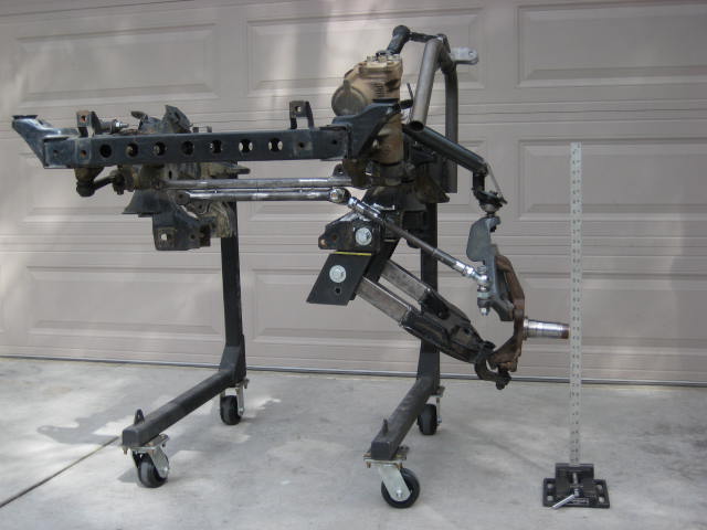
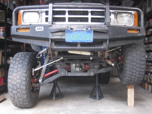
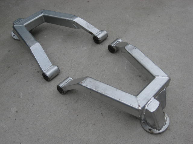
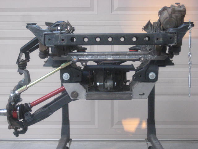
From the mock up I did some CADD work and designed the Drop Bracket Subframe. I then had the pieces laser cut from 1/4" plate. There was also some square tube and angle also 1/4" that I cut on my chop saw. I tacked everything and made sure the CMdiff sat as low as possible while still being protected by the sub frame.
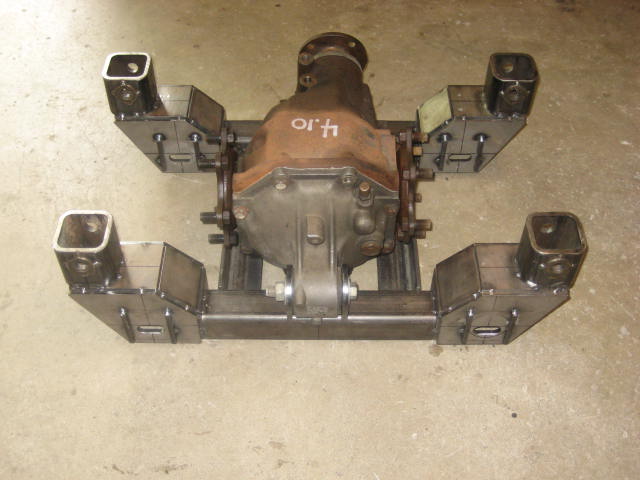
Next I built the diff drop hanger brackets.
I wanted the hanger brackets to be independant from the sub frame to make it easy for removal and service. I also wanted to be able to swap it out and hang a Supra diff.
I installed the parts onto the test frame and plugged in the CV axle from the previous build but it was about 1/2" long and the plunge bottomed out.
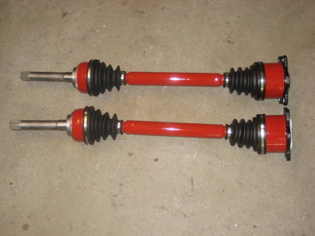
I built a new set of CVs a 1/2" shorter. I built them the "cut and sleeve" method this time to save on cost.
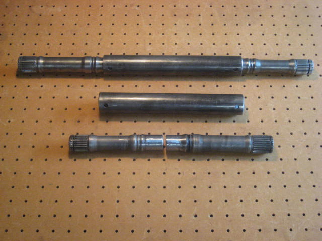
The 1/2" reduction worked and I found the desired results.
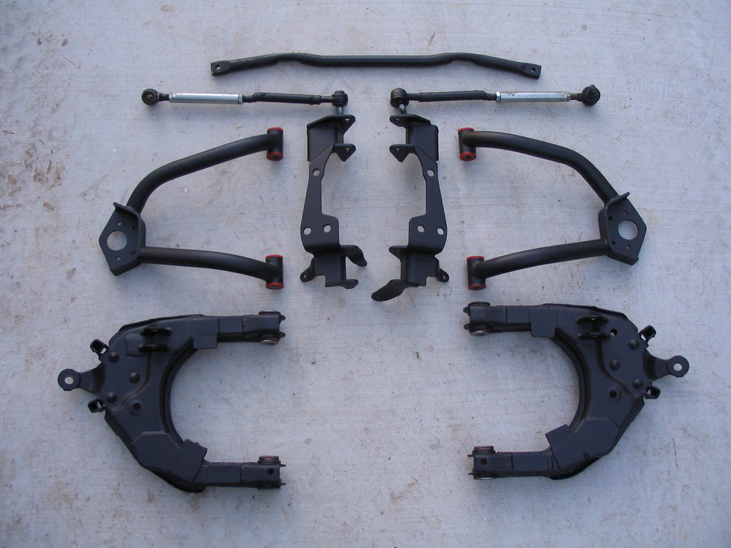
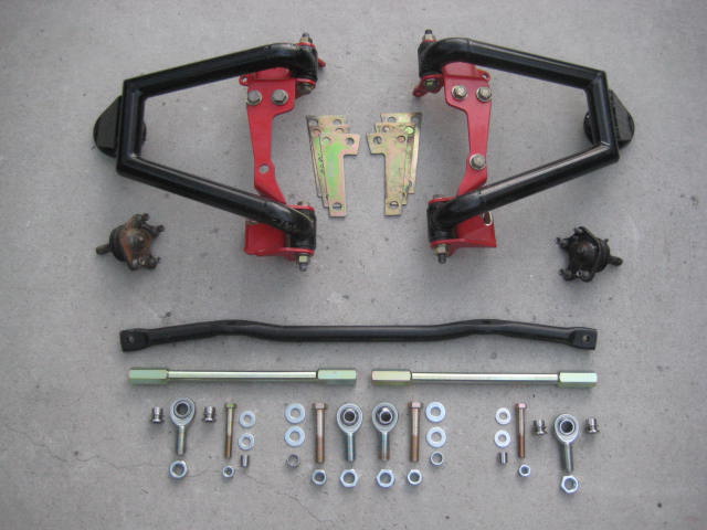
From there I built bump stop brackets to set the "up travel" and limit straps attachments to limit "down travel". With limits set the result was between 14-15" of usable travel.
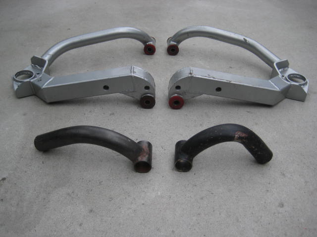
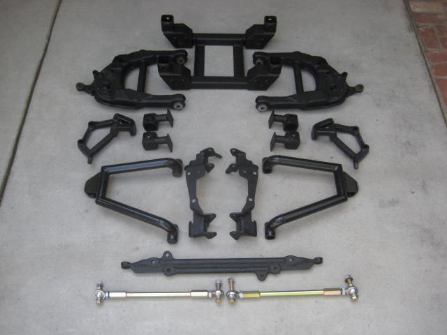
Here is a photo of some of the componants used to make up the system.
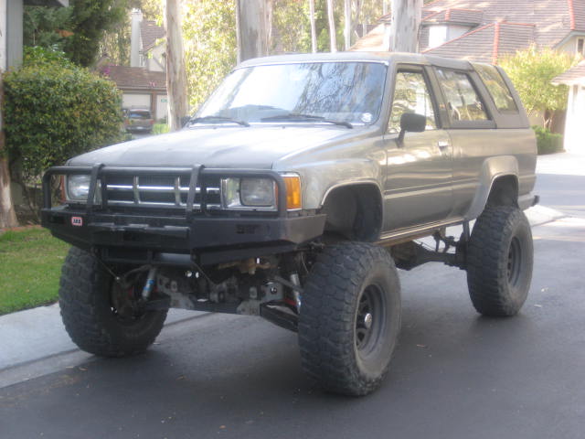
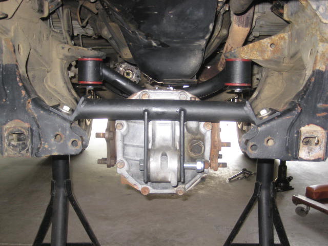
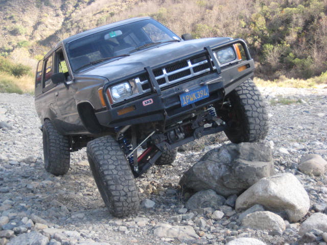
I had the rig on the road in November 2013. Here is a photo one of my first trips up a local dry river wash.
The set up has held up well the past year and a half. I've made a few camping desert trips, a couple of trail runs with light crawling, a pre-run or two, served as chase rig for a couple of races, took a bunch of road trips, and its been my daily driver. Its been a fun rig.
I know, everyone bags on the drop bracket style of lift but there are some advantages. True, it does not provide any more travel, but it provides Lift for larger tires and more ground clearance. It also provides room under the oil pan to reconfigure the front differential. I'd been running the ProComp Stage II Drop Bracket Lift with my Long arms for a while and it fits 35s perfectly.
I had also been running the CMdiff set up that one of my customers turned me on to. The guys name is Craviotto and you can read his build thread here on YotaTech.
Anyway, the ProComp stage II kit was great for lift and the CMdiff took care of the CV angles and plunge. But, the travel numbers were just standard long arm / drop bracket combo kit at 12" metal to metal.
The Rancho UCA pivot relocation brackets worked up top, so LCA pivot relocation should do something for the bottom as well. It did, it decreased the LCA angle and corrected the lower Ball Joint issues. I don't remember the exact numbers but I believe it was in the 15" range.
From the mock up I did some CADD work and designed the Drop Bracket Subframe. I then had the pieces laser cut from 1/4" plate. There was also some square tube and angle also 1/4" that I cut on my chop saw. I tacked everything and made sure the CMdiff sat as low as possible while still being protected by the sub frame.
Next I built the diff drop hanger brackets.
I wanted the hanger brackets to be independant from the sub frame to make it easy for removal and service. I also wanted to be able to swap it out and hang a Supra diff.
I installed the parts onto the test frame and plugged in the CV axle from the previous build but it was about 1/2" long and the plunge bottomed out.
I built a new set of CVs a 1/2" shorter. I built them the "cut and sleeve" method this time to save on cost.
The 1/2" reduction worked and I found the desired results.
From there I built bump stop brackets to set the "up travel" and limit straps attachments to limit "down travel". With limits set the result was between 14-15" of usable travel.
Here is a photo of some of the componants used to make up the system.
I had the rig on the road in November 2013. Here is a photo one of my first trips up a local dry river wash.
The set up has held up well the past year and a half. I've made a few camping desert trips, a couple of trail runs with light crawling, a pre-run or two, served as chase rig for a couple of races, took a bunch of road trips, and its been my daily driver. Its been a fun rig.

 07-22-2015, 08:58 AM
#6
Registered User
Thread Starter
Coffey50,
Thanks, I spent some time writing this post. Finding old photos and trying to remember details got me re-motivated to the possibility of production. As we speak parts of the kit are being scanned and measured at a local company involved in manufacturing this type of product.
As for this kit being on my 4Runner and on My Truck the answer is sort of. Sounds like you have found and read the threads I wrote on both rigs so you can see how things are evolving.
In brief summary, the only parts that are Rancho on either ride is the UCA pivot location bracket. But these brackets have been modified because the unmodified pivot bracket will not allow the droop I am showing. I also modified the bracket to allow the use of different bushings as the Rancho bushing have long been discontinued and impossible to find. The production pivot relocation bracket will be improved and even further removed from the Rancho design making my design completely unique and a stand alone system.
As for selling this new system on my website, that is the plan. It will likely replace my current Long Arm kit that uses modified stock UCAs and LCAs. I am sick of the labor of processing of cores and performing the fabricating and welding the LCAs. I am probably limiting the production of the Long Arm Kit to 100 units. I am currently finishing up 94/100. I will still sell the DIY version of the Long Arm Kit.
Trending Topics
07-22-2015, 05:40 PM
#8
Registered User
Thread Starter
I had a T-100 front drive shaft from a guy doing a solid axle swap and it was a hi-angle unit. I don't know which trucks or 4 Runners and what years have high angle units but the original drive shaft from my 1986 4 Runner didn't. The Drive shaft on my 1985 SA truck does. Beyond that the high angle unit was lengthened a bit and it reached down and over to connect to the yoke. If you look through the pictures on my 4Runner build thread you can see what is going on.
07-22-2015, 05:46 PM
#9
Registered User
Thread Starter
I have not written about it or posted any photos but another option is to narrow the tube of the diff assembly. This way the yoke is still on the passenger side and the drive shaft angle is not as extreme. The down side is shortening then splicing back together the long side axle. I'll have to do a write up.


