FMU Field Monitor Unit Install in Gen 3
 07-15-2007, 02:51 PM
#1
 Well as promised, I finally got a handle on Photo Bucket (Thanks Rodk Slide) This will be a multiple part install. It si socmpleted but I was never able to resolve the issue with the low temp reading even with a new sensor which by the way the part number discussed here did not fit my sensor plug end. Bottom line is I am still 10 degrees low with the new sensor. so here it is with pictures and commentary by yours truly. Please feel free to comment. I hope this will help the next Yota fan to make their installation simple and fun.
 As promised I have the pics and the write up for the Field Monitor Unit that I installed on my 1998 SR5 4Runner.
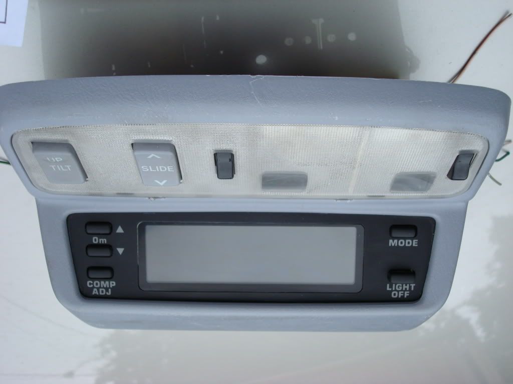
The project began on eBay where I acquired the unit from a seller in New Zealand. For those not familiar with this accessory, this is a replacement for the overhead console that controls the operation of the sun roof as well as the map lights. In addition, this unit will display compass headings, barometric pressure, altitude, and temperature albeit in degrees celcius. This accessory was never offered in the US and was only available to what is referred to the Japanese domestic market (JDM) on select Hilux Surf models 1996-2001. For more information you can do a search on FMU or Field Monitor Unit and find the write ups for Rock Slide as well as Midiwall. Both of these gents write ups were excellent help for me. I did have a few issues but I will say that Rock Slide was a HUGE in helping me to understand some to the ins and outs. I hope that I have done him proud on this write up and pictures. There are some subtle differences but in general our instructions/write ups are the same.
My unit came complete with a double switch setup for the sunroof, open/close and a separate switch for tilt. This was the identical set up as was installed on my 4Runner. Some tools you will need are as follows. Remeber this is just a list of some of the tools I needed. You may need others or just improvise from your own tool box
#1 phillips
#2 phillips
small flat tip screwdriver
med flat tip screw driver
Diagonal cutters
Utility knife
10 mm socket
ratchet handle
drill w/bits
wire strippers
nylon wire ties (small)
metal coat hanger
While not necessary I would recommend crimps instead of soldering as it is quicker then cutting into wires and trying to soldering them in then insulating them adequately:
Crimper
18 gauge wire crimps
Impact screw driver
Ball Peen hammer
Electrical tape
several 25 ft rolls of wire in various colors as it just helps to keep things straight when hooking up the wires
One other thing I did shortly after starting this mod was go to the local wrecking yard and salvaged an old wiring harness from a 90's Honda. Any Japanse vehicle would work I'm sure but getting several long runs are definitely useful. The other upside is that they are the same wires that are already installed in our vehicles. This also provided me with a few other nice to haves, several section of various size split ribbed tubing (harness protection) as well as some pre-made ground wires with attaching lugs.
Lets get started. If you have a sunroof then this should be what you will see when you first start, the OEM split consoles mounted in the roof.
The FMU and sensor should look similar to this.
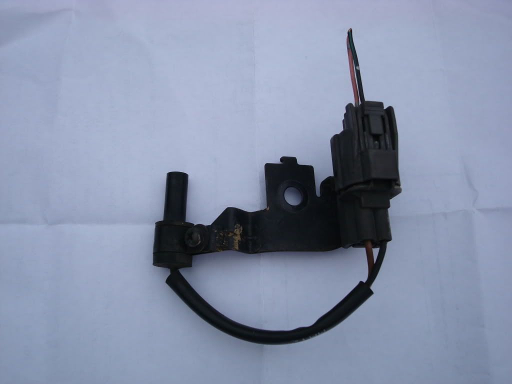
Remember that there were different sensors manufactured for this accessory. Yours may look different. If you get one included with your FMU, ensure that you have the plug along with the socket with two wire leads. This sensor was mounted to special mounting plate that had the mounting hole as well as an alignment tab. This will be very helpful when we mark and mount the the sensor in the fender well. This sensor was also located on the Hilux Surf below and to the right of the LEFT head light. I mounted mine in this same location. You will see why and where when we mount the the sensor.
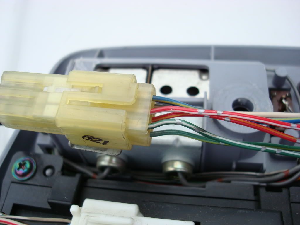
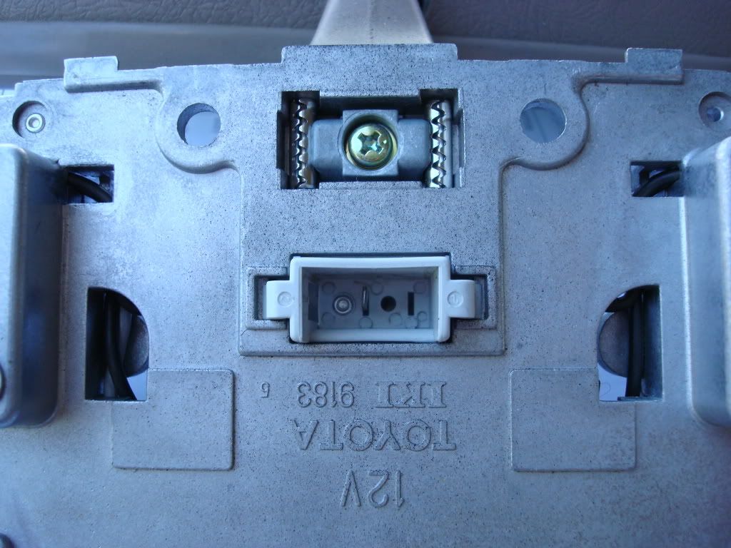
When you flip the FMU over you will see two connectors.
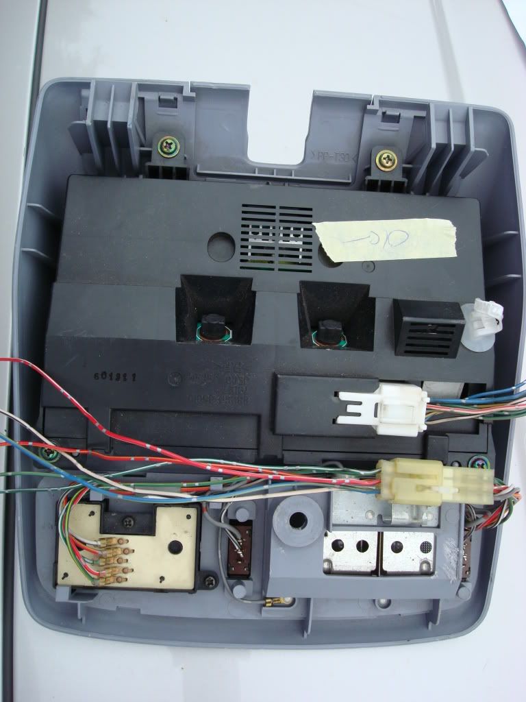
One connector is for the sunroof control the other is for operation and inputs for the FMU.
Begin removal of the OEM controls as follows: The sunroof control console can be removed with a single screw that is located under the flip down cover on the sunroof console. Save this screw as you will need it to secure the FMU later. What makes this an easy install is that both the plugs and the FMU mounting hole line up with the corresponding components on our 4runners.
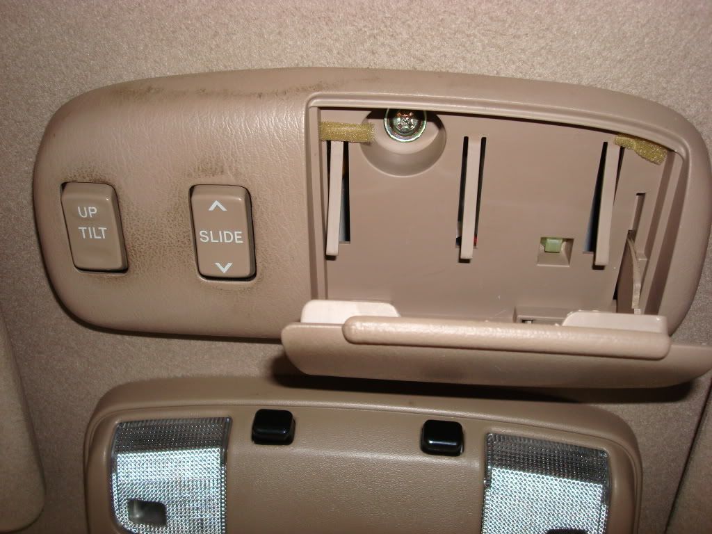
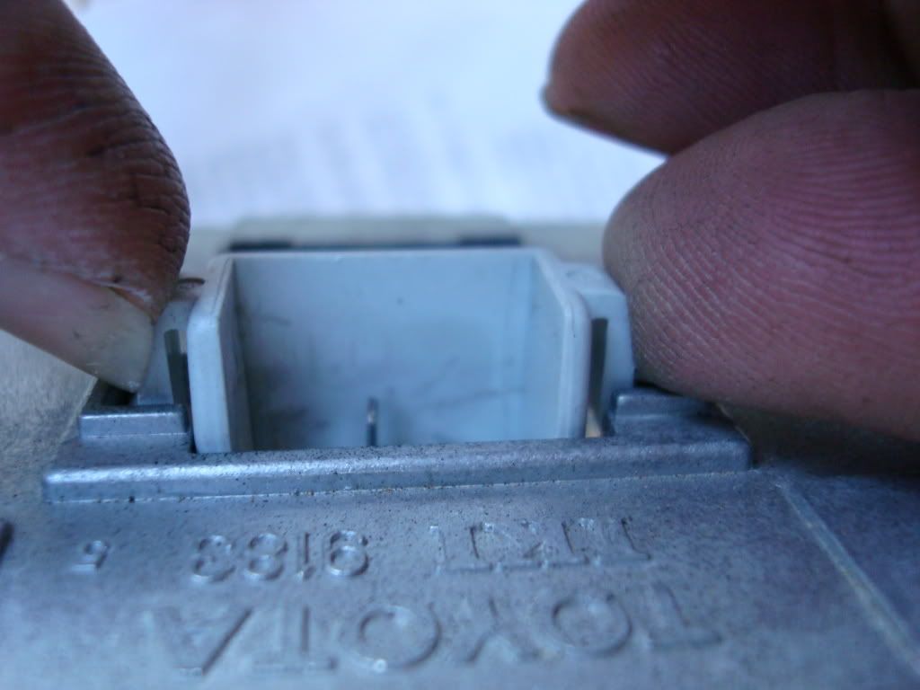
Once you remove the screw you will see the connector holding the sunroof console. This connector has a tab that just requires you to squeeze and pull.
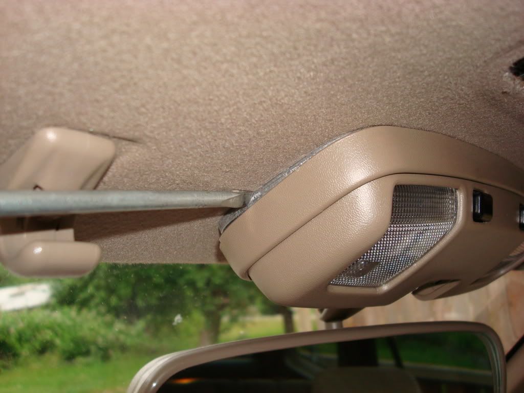
Using a small flat tip screw driver, you will need to remove the small piece of trim that surrounds the mirror post.
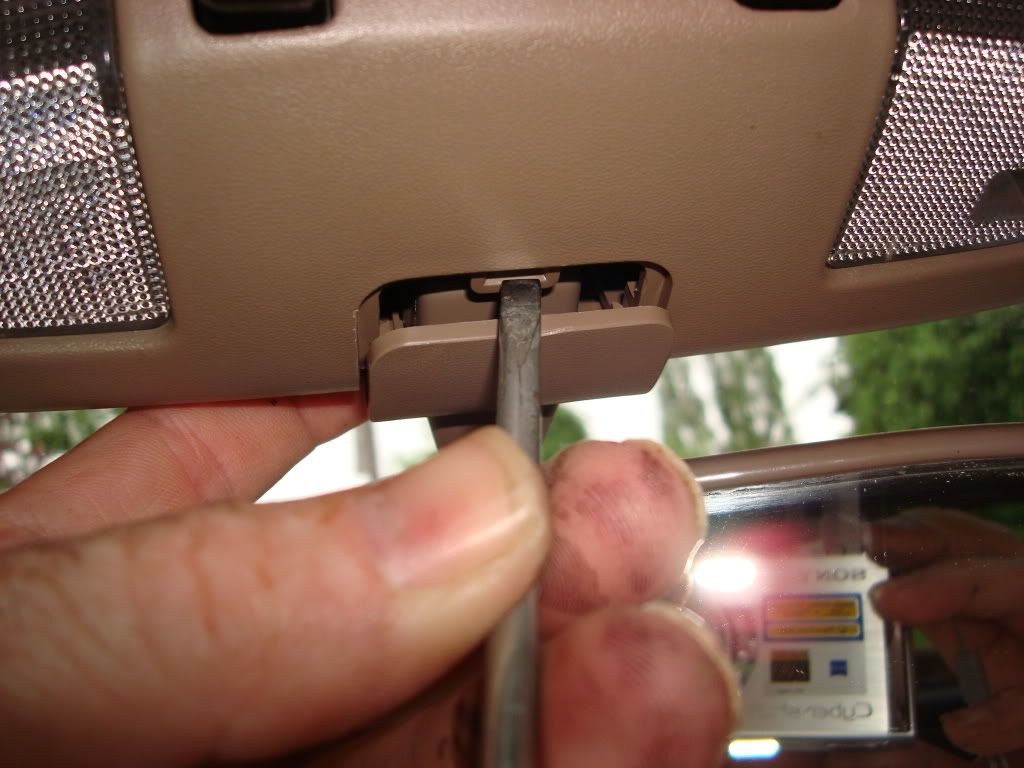
Using the same screw driver, gently pry under the edge of the mirror mount from the side. The cover is just that, a snap on cover. There are several small over clips that hold the cover in place over the metal mirror mount. Once you get the end loose, you can just grasp the edge and it should just come right off.
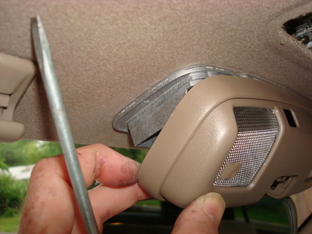
You now have the mirror assembly exposed. You will note the location of four (4) screws that secure the mirror to the roof. Retain the screws when removed. You will use two of these to replace the modified mirror mount.
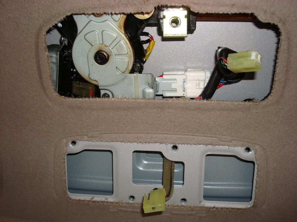
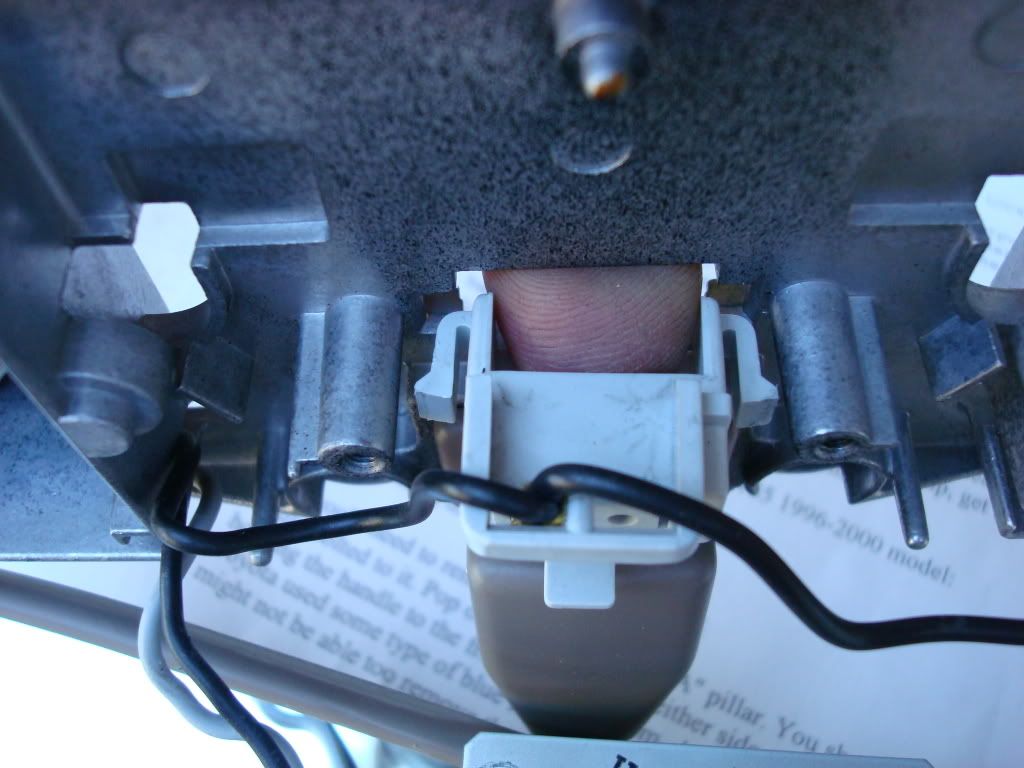
Gently pull the assembly from the overhead. You will note a plug that connects into the assembly. This is the power connection for the map lights.
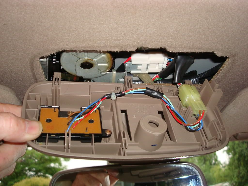
 Just squeeze the tab on the white plug and pull it from the mirror assembly. Set the assembly aside for now.
Now we have both OEM consoles removed with two connectors visible.
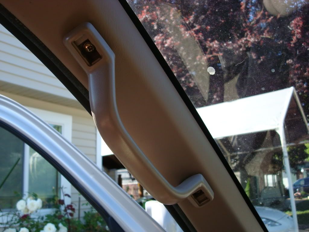
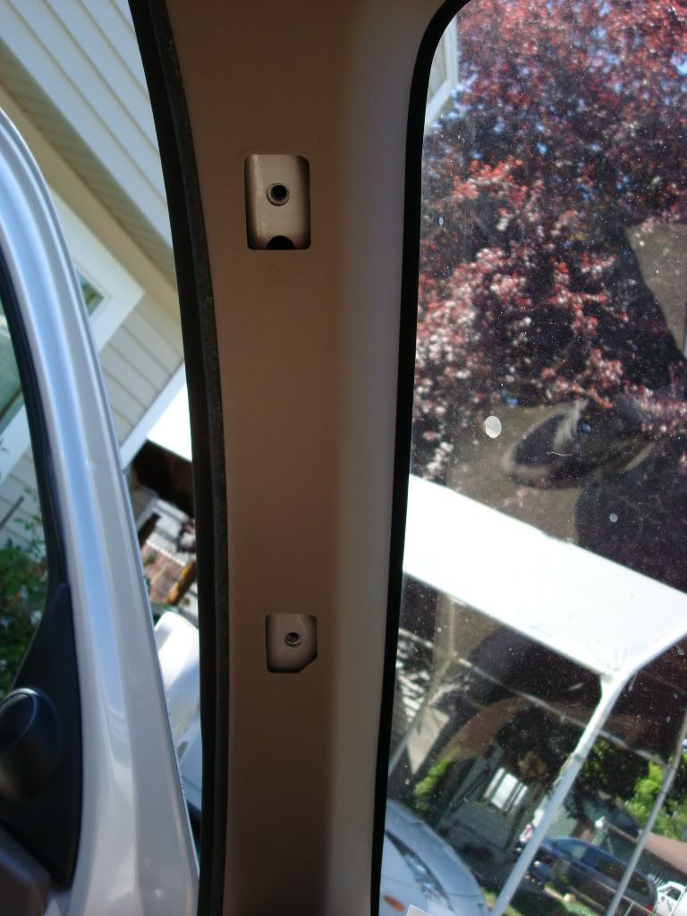
Next step will require the removal of what some refer to as the ?Oh Crap? handles. I would recommend removal of both handles from the Driver and Passenger side A-pillars. Routing behind the covers on the A-pillars matches the factory wiring routes and provides for a more protected and professional install.
Removal of both A-pillars was not done on the other installs that I read and used but you can save yourself some routing of extra long wires all down the Drivers side A-pillar. You will be routing a minimum of 4 wires down the Drives side, 2 are for the temperature sensor and at least one each for connections to the Clock plug for illumination and ignition switching. If you chose to route a 12vdc constant power lead, then you will also need to route that down the drivers side a-pillar or use the ower lead from the OEM map light lead. I will show you the lead you can use as I utilize the plug that is installed in the mirror mount.
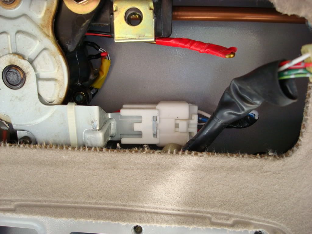
You will need to route a wire to the ABS unit for motion sensing for the compass to operate. 1996-1998 ABS units are located behind the passenger side floor kick plate. I am not exactly sure if this is the location of 1999-2002 Gen 3's or not but most likely is the same. It is a shorter run down the Passenger side A-pillar and will be less congested. There is more then enough room and once you get the pillar covers off the routing is a breeze.
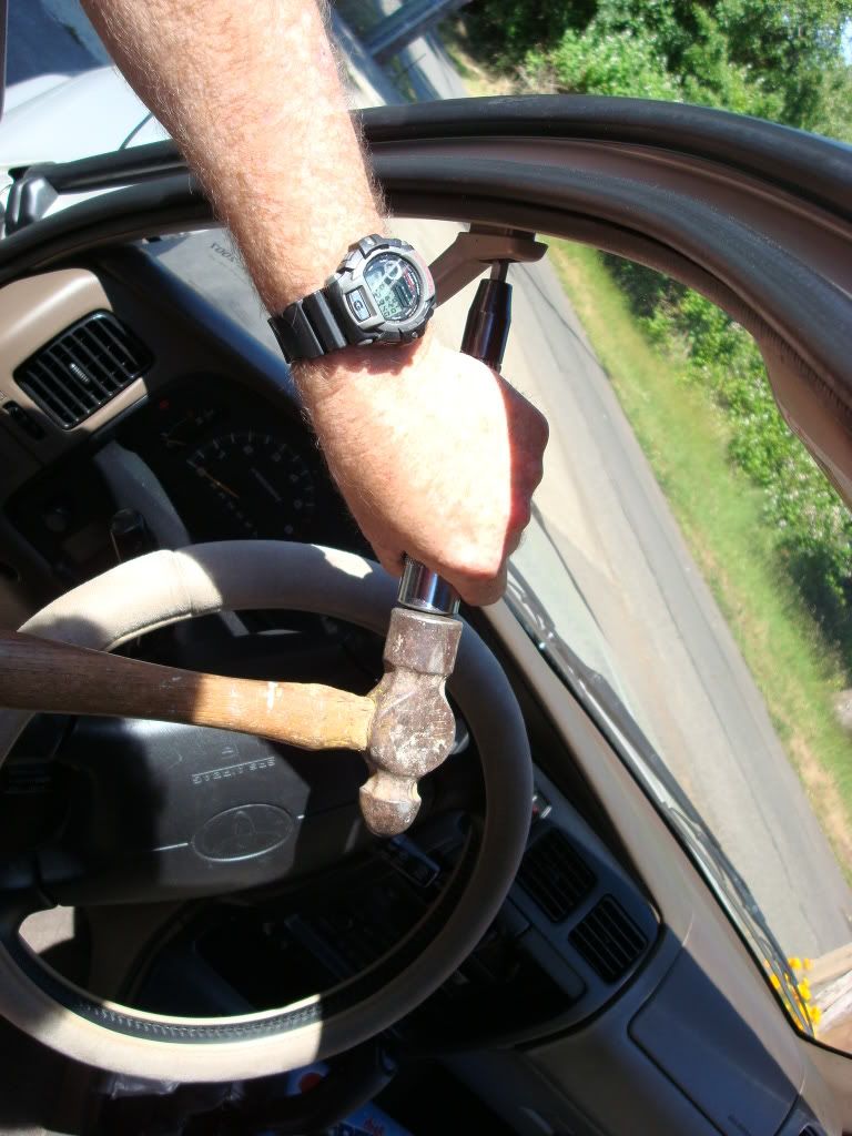
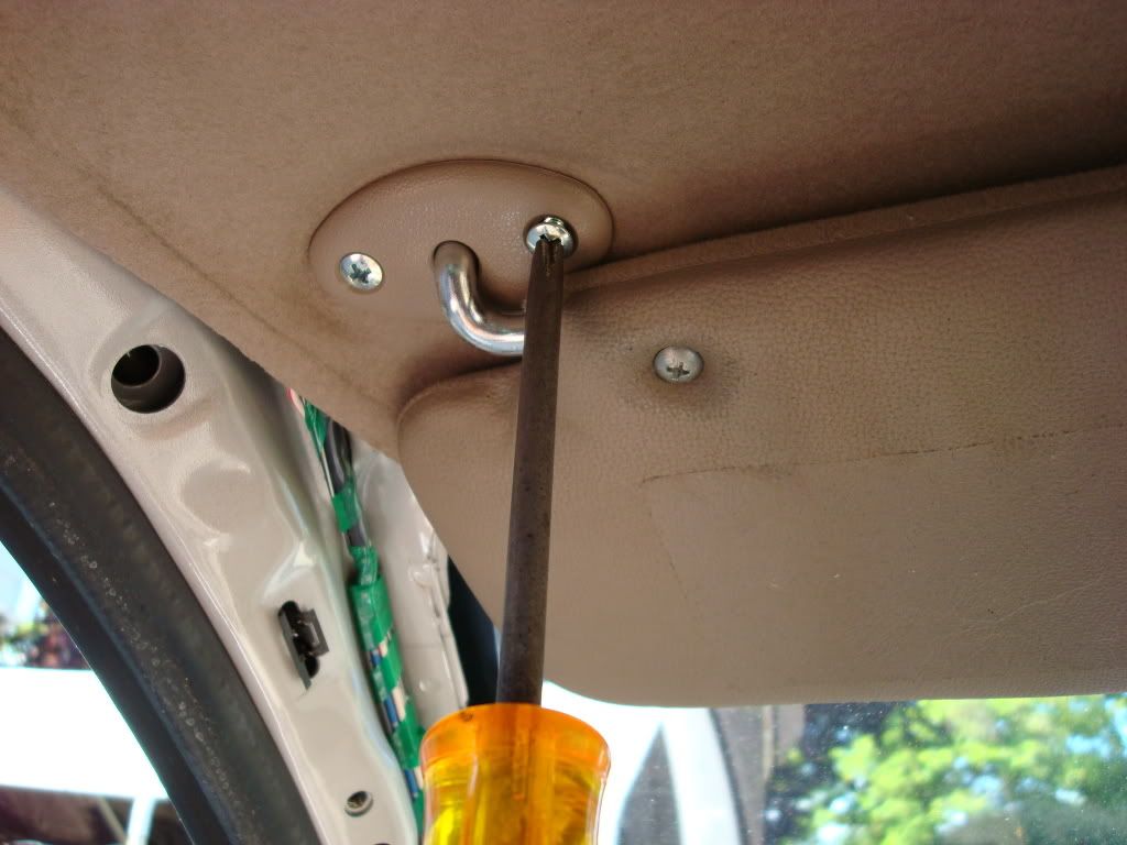
Continuing with the removal: Using the small flat tip screwdriver, gently pry the screw covers from either end of the grab handle, save these for re-installation. If you do not have an impact screwdriver the next step will be difficult as Toyota uses a blue liquid locktite compound on each of the hold down screws. As both Rock Slide and myself found out you may be able to get them out but chances are you will just strip the heads which is what I did until I remembered I had an impact. The drivers side is a bit tricky as there is not a lot of room to get a good clean swing at the impact with a ball peen hammer. I would recommend a second set of hands to assist. I used my son! The upper one is pretty easy. I had tried to remove the screws with a normal phillips screw driver and proceeded to strip the head. With the first couple of strikes with the hammer on the Impact, i was able to really seat the bit and a few more strikes and I felt the head move. I was relieved that I would not have to drill/cut the screw head.
 .
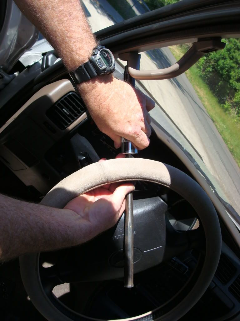
. The lower screw proved to be the challenge. I ended up using a long metal punch with the impact. This necessitated the use of a second person (my son) to hold the impact while I held the punch and and hammer. Several sharp hits broke the screw free, I then just used a Phillips screw driver to remove the second screw.
Handle removed.
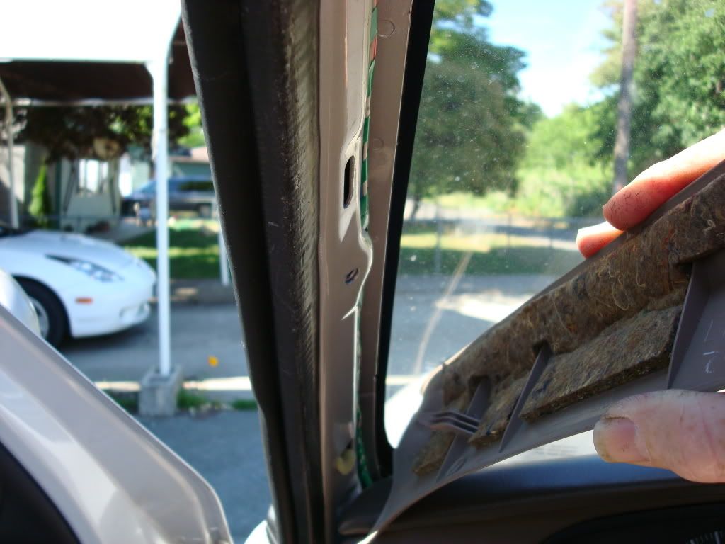
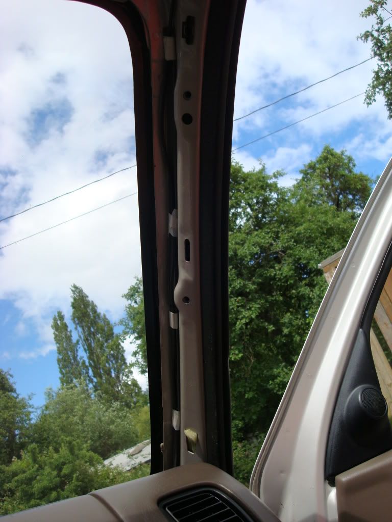
The pillar trim covers entire trim area from the dash to the rear edge of the front door. You can just grasp it with your fingers and lift the edge up or use the small flat tip screw driver to lift the edge enough to get your fingers under it to pull it towards yourself. There are several plastic molded clips that will just release with enough upward pressure. You won't break anything when you start to lift the edges. You need to know that there is a hook near the base at the dash edge of the pillar trim which requires that you pull the trim upwards toward the roof and it just slips right out. Mine had a small piece of foam rubber to help keep it snug. The back edge slips under the rear door trim so after you get the edges clips free and the front hook off, you should be able to just pull the remaining end out.
Next you will need to pull the visors. This allows you to pull the headliner down without bending or putting creases it, and provides more room to route the wires. I would recommend doing both sides at the same time, both pillars, grab handles and visors, just saves time.
Using a wire coat hanger that has been straightened, make a small loop end. Using electrical tape, take the two wire ends you have selected for your temp sensor lines and tape them to loop.
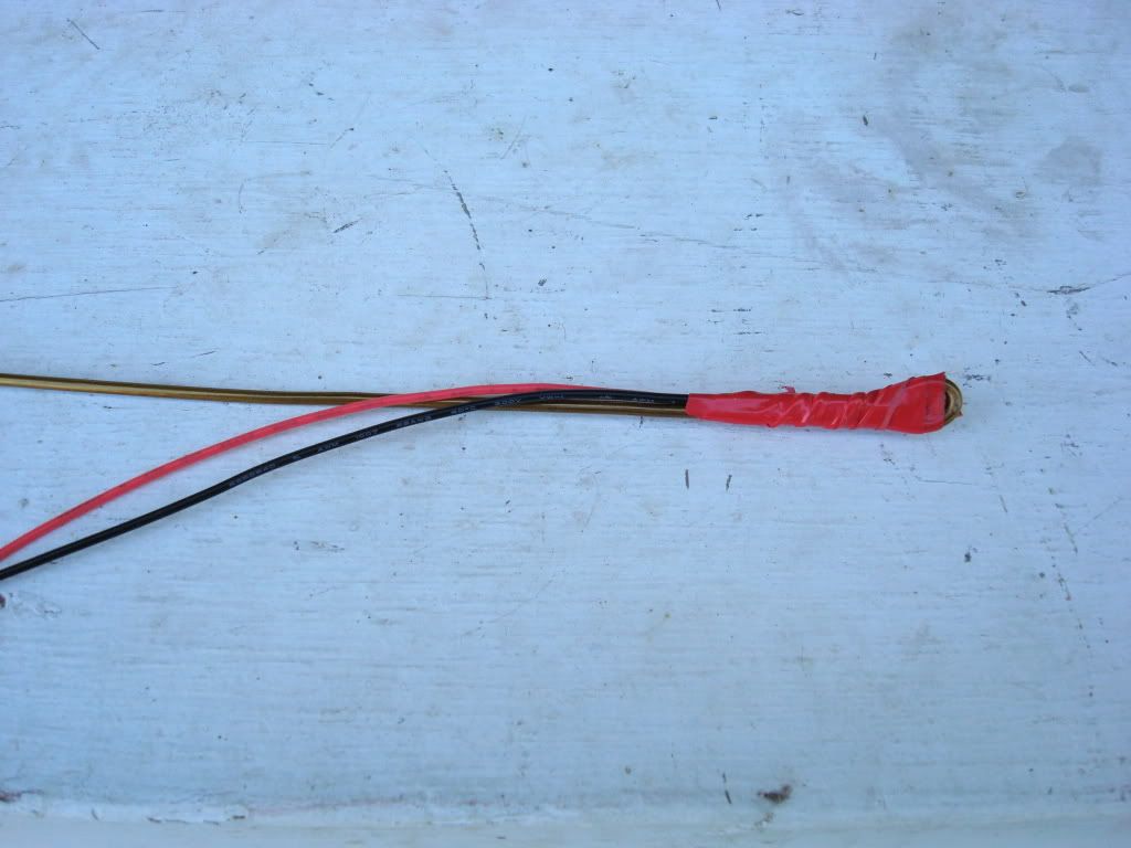
Gently pull down the headliner about 2 inches at the door side and push your wire towards the sun roof control opening in the head liner.
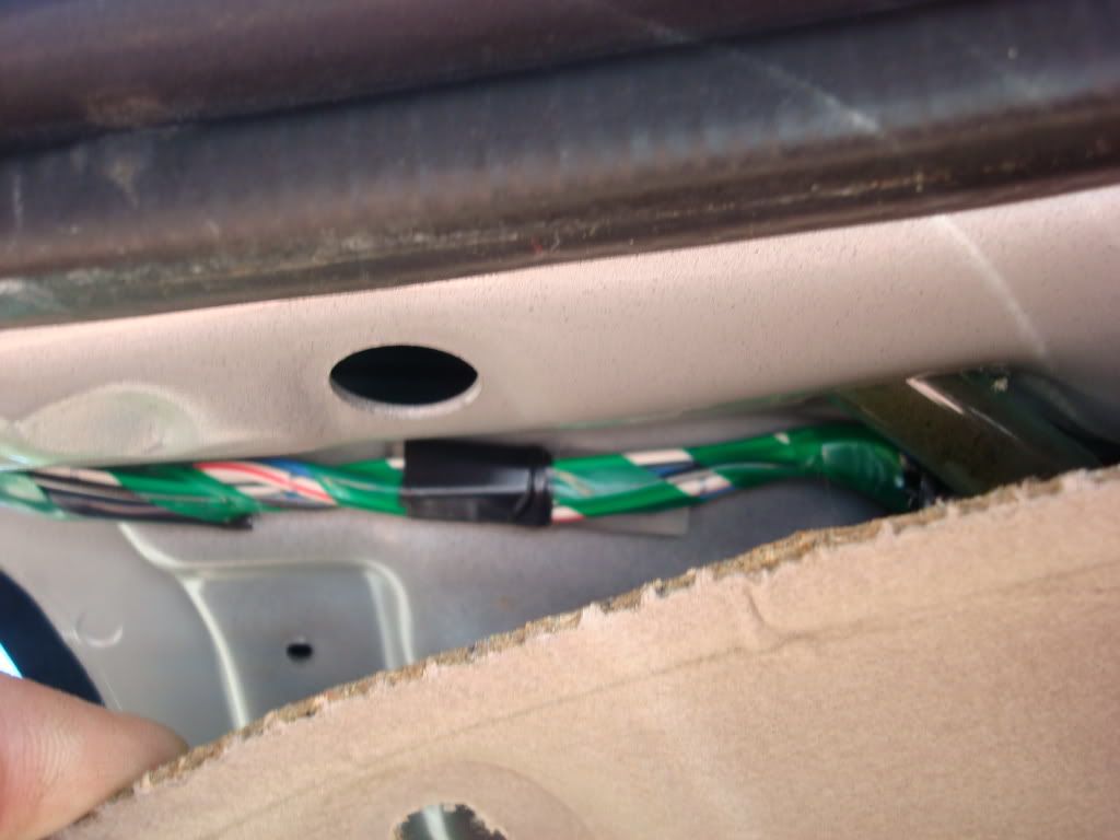
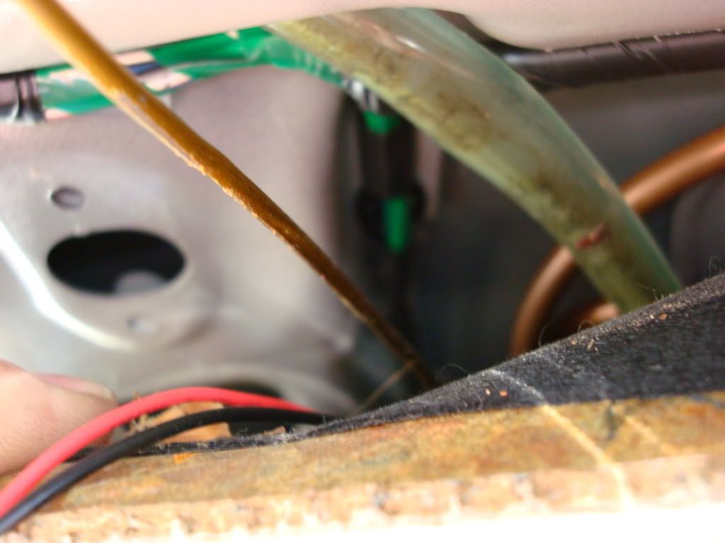
You may have to wriggle the wire around a bit to find the optimum routing path for the wire. Don?t force the wire into the opening as you can snag some interior components of the window operating mechanism or mounting hardware. Take your time it really is quite simple. Once you see the wire end at the opening of the headliner where you want it, just pull the end downward through the opening and remove the tape. Pull about 12 inches of slack through making sure that the wire pulls through smoothly and without binding. Be sure to use tape to mark the ends as to what they are going to be used for.
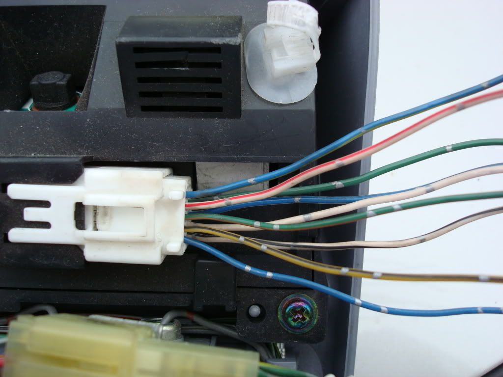
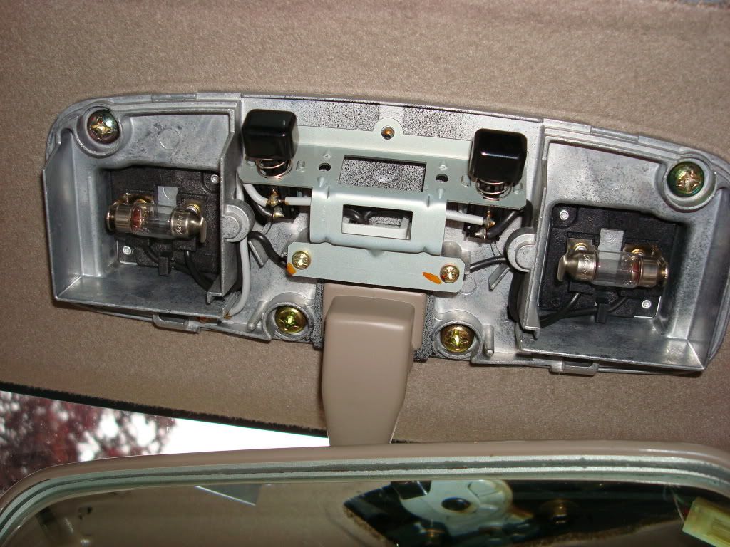
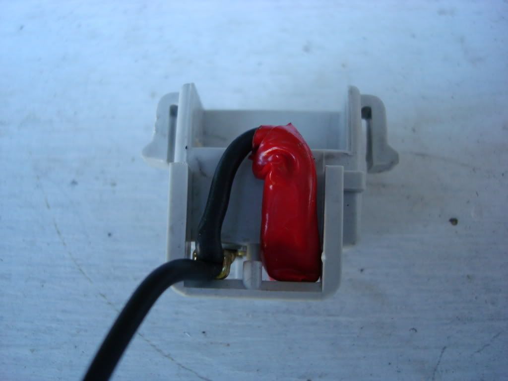
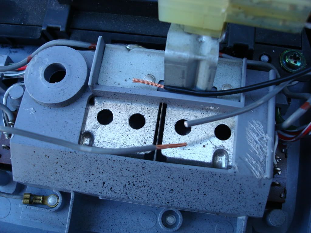
Our next target is the map lights. The US version lights are very different then the lights used in the FMU. The US version uses the fuse style bulbs while the FMU uses the plug and socket style lamps. First we need to remove the white socket plug from the mirror mount.
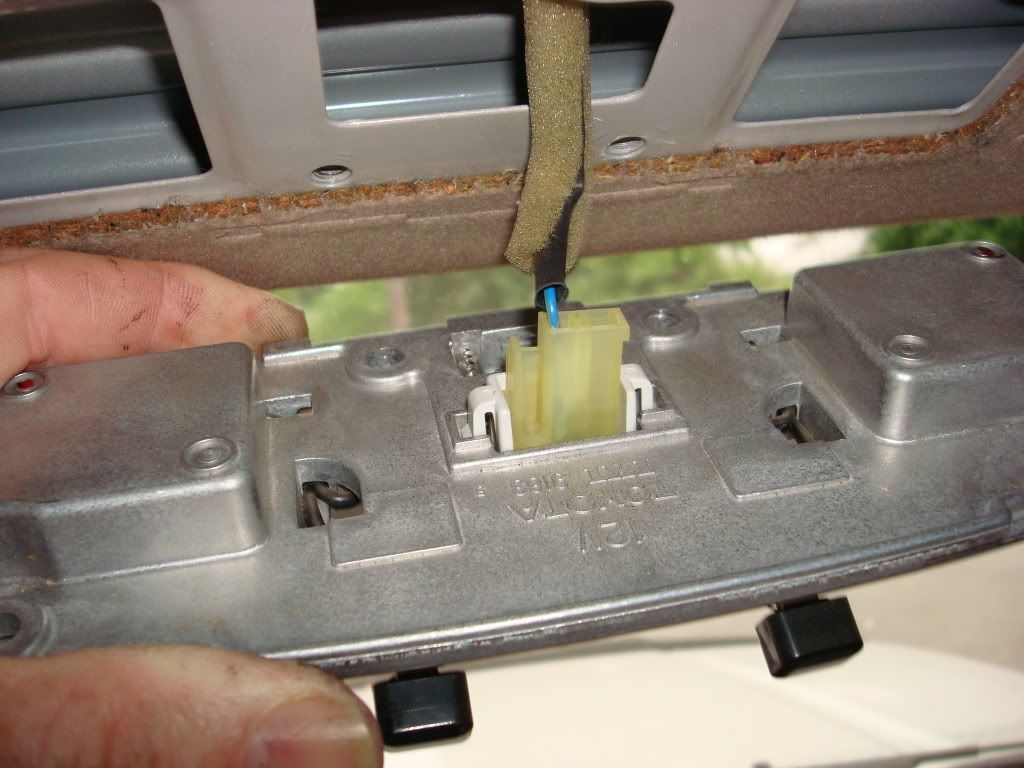
Grasp the open end of the socket and squeeze the edges Pinch the open end of the plug which releases the tabs on the opposite side then just push the socket out of the mount.
Remove the two screws holding the switch plate to the mirror mount which will allow us to get at the wires going from the switch to the plug. You will note that there are two wires going from the switches to the plug. Only one will be needed for the map lights on the FMU. You can use this second wire for your constant 12vdc for the FMU if you desire. That can save you routing a wire to the Clock for constant 12vdc.
If you remember when we removed the console, we disconnected the single wire from the map light console connector. I chose to use this connector intact vise cutting up the connector and mashing the pin to force fit it into another connector. I ended up with 3 connectors in my overhead, but it just makes it easier to attach when I plug in everything. I also chose to only use one end of the double wire and just folded it back on itself and used electrical tape to insulate the end as I had already run the 12vdc constant wire down the Drivers side A-pillar.
The FMU map lights use a gray wire for power so I just cut this wire in the center above the map light wells as you can see from the picture, stripped it and crimped the map light wire to one of the two black supply wires on the white socket we removed from the mirror assembly.
This is the finished crimp of the power supply to the FMU map lights.
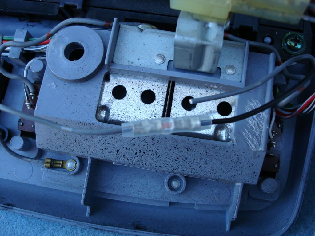 No need to worry about the loose end as it goes to no power and is not needed.
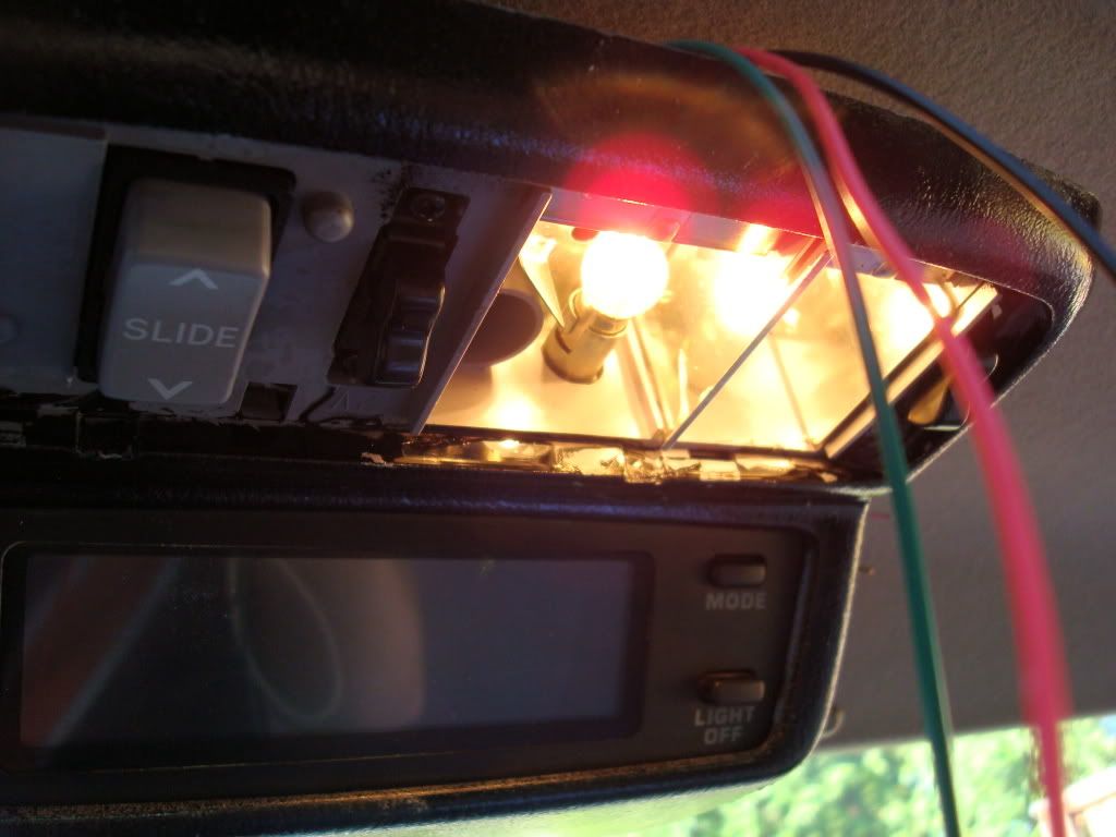
With the splice completed and plug and socket all connected to where they need to be, I did a test of the map lights. Holding the FMU in one hand I just slipped the single plug into its socket and then just pressed the two map light switches and we have light! And to quote God ?It was good? (Genesis 1:3)
More to follow

Last edited by Ritzy4Runner; 07-16-2007 at 07:56 AM.
 07-15-2007, 02:59 PM
#3
Well I don't know how to do that just yet, LOL I just figured out how to post pics to the forums, but as soon as someone shows me or tells those who control such things, I will be glad to post it where ever here. I will eventually have a single document once I finish the installment version as I am doing this on the fly. Hope to get it done before I leave for California this week. Stay tuned for the next install Also I just finished up a reverse gauge install. I could not believe how simple this mod was on a Gen 3, and yes I will post it with complete instructions.
07-16-2007, 05:30 AM
#6
I got mine on eBay for around $120 plus shipping and it had to come from overseas. The last one I saw about a 2 weeks ago went for over $100 and it didn't come with a sensor. Trying to make the images a bit smaller if I can figure out how to do that on photobucket, but don't want them to be too small
07-16-2007, 06:01 AM
#7
Looks great Ritzy! Definitely gets my approval 
I have linked this write up (and your previous thread on this subject), along with Iceman's write up to my original FM write up thread. In case someone searching for info on these FMs stumbles across my thread, they will be able to find yours and any one else that has added a FM relatively quickly.
Again, nice work.
Trending Topics
01-09-2008, 06:37 AM
#8
Registered User
Join Date: May 2007
Location: Denver metro area-CO
Posts: 2,175
Likes: 0
Received 2 Likes
on
2 Posts
bump-I missed all this stuff back last summer-very nice writeup excellent use of photos and I am glad you add the small details such as how to loosen those handle bar screws
this looks to be beyond my mechanical ability- now that you have done it and the photos are here for others to follow-could you guesstimate the total time involved for an install with all pieces present?
this looks to be a nice alternative to a cheesy aftermarket display-I really applaud all of you guys initiative to not only do these mods but them share them with noodniks like me, dangerous with screwdriver in hand.


Thread
Thread Starter
Forum
Replies
Last Post
jasonty
Pre 84 Trucks (Build-Up Section)
41
12-23-2018 01:00 PM


