BlazeN8s 85 L.A./ 86 L.T. Build-Up Thread
 01-03-2013, 09:07 PM
#21
Registered User
Thread Starter
My friend Albert (aka Mantruck) turned me onto a Craigslist find. I guy just a few miles from me was selling a brand new Skyjacker suspension setup he had gotten for his 85' 4 Runner. The deal was for 4" rear lift springs, 3" front springs, and All-Pro Shackles all for $300. He sold the 4 Runner and never installed. It was one of those buys you know was a good deal but it really wasn't a long term investment.
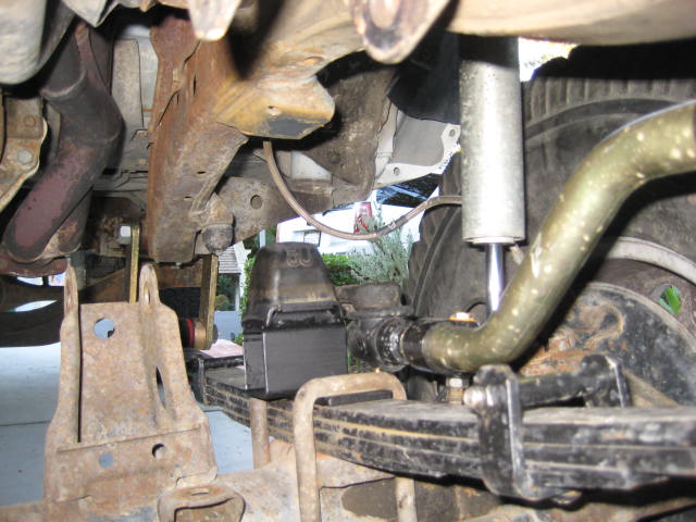
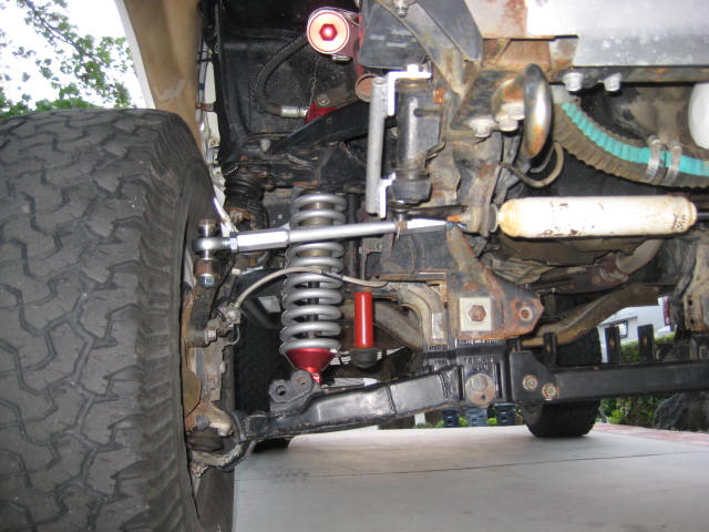
The new front springs had one less leaf than the old. The new springs added about 1" of lift. Then I added the All-Pro 6" greasable shackle. The stock shackle is 3-5/8" so it added another inch. I testimate the before lift was 2" over stock and the after lift about 4". The pinion angle at the trunion measurement is 5 degrees. The pinion and driveshaft don't look right but the caster steers ok. I probably need to get some shims or a shorter shackle. If I end up staying with 33s I would like to lower the front an inch so maybe a 5" shackle and with spring settle it will work out.

The new front springs had one less leaf than the old. The new springs added about 1" of lift. Then I added the All-Pro 6" greasable shackle. The stock shackle is 3-5/8" so it added another inch. I testimate the before lift was 2" over stock and the after lift about 4". The pinion angle at the trunion measurement is 5 degrees. The pinion and driveshaft don't look right but the caster steers ok. I probably need to get some shims or a shorter shackle. If I end up staying with 33s I would like to lower the front an inch so maybe a 5" shackle and with spring settle it will work out.
 01-03-2013, 09:08 PM
#22
Registered User
Thread Starter
Another complication I found with a 4" lifted front was the Sway Bar, the Torque Arm and the Drag Link not working properly. And now the limit strapped 7" travel shocks had zero down travel. I talked with Tech Tim about some of these issues and here is what I ended up doing.
For the Torque Arm I just omitted it. It was adjustable and could have been nice for street use but for off roud everbody just removes them. Its main function is to controll axle wrap when braking. I really noticed the difference in before and after. When I removed it, the end up at the frame had a siezed bolt and steel sleeve. I had to use a cut off wheel to get it off, thus destroying it. The bushings were bad anyway so oh well. I may look for a new bolt and sleeve as well as bushings but it may be hard to find.

For the Torque Arm I just omitted it. It was adjustable and could have been nice for street use but for off roud everbody just removes them. Its main function is to controll axle wrap when braking. I really noticed the difference in before and after. When I removed it, the end up at the frame had a siezed bolt and steel sleeve. I had to use a cut off wheel to get it off, thus destroying it. The bushings were bad anyway so oh well. I may look for a new bolt and sleeve as well as bushings but it may be hard to find.
01-03-2013, 09:11 PM
#23
Registered User
Thread Starter
The Sway Bars would also be nice for the street but for now I am omitting these as well. The SkyJacker kit came with longer bolts and tubes to compensate for the added lift but no bushings. The old bushings were toast. I think I can find some new bushings and maybe some quick disconnects.
The factory Drag Link no longer works properly at 4" of lift. It is not adjustable so it is now too short and the angle exceeds what the joint can handle. It doesn't allow the suspension to droop out. The link at the J-arm hits the top of the U-bolt at droop. I did some research on how to fix these problems. One solution is a "J-Arm Ball Flip" the other is an adjustable Drag Link
The J-Arm Ball Flip is an interesting modification that involves grinding the back side of the ball stud and using a 50 ton press to remove the ball. Then you flip the ball around press it back in and weld. If you go this route and keep with the factory drag link you now have to cut the drag link and rotate the end 180 degrees to sit on top of the J-arm. I had read Skyjacker was selling J-Arms that had been flipped so I gave them a call. The gentlemen I talked to was very knowledgeable and helpful. He explained the procedure in great length and said he does have J-arms with the ball flip for sale. He was not sure on the price but checked on it and called me back, It was in the $500 range. He also said its not recommended to modify the factory drag link. He said the ball joint flip was designed to be used with a 4" adjustable drag link and this assembly was designed for 7" or more of lift. Kind of an 1980's high rider show truck with 40" tires thing I guess. He thought I should be fine with out doing a Ball Flip and just using an adjustable Drag Link.
The 4" Adjustable Drag Link from Pro-Comp is what I went with. Skyjacker, Superlift and Pro-Comp all offer them, but I wanted it fast and Summit Racing had a Pro Comp unit (that was also the cheapest) in stock and it shipped UPS Ground in 2 days. The instructions were good and it went in without much difficulty. Being adjustable was nice and I was able to dial it in and center the steering wheel fairly well. Now the suspension can droop as far as the springs let it and it no longer hits the u-bolt.
01-03-2013, 09:13 PM
#24
Registered User
Thread Starter
For replacement shocks I happened to have two pairs of Bilstein 5100s from my old traction bar set up from the Fordota. These shocks are a 9" travel and have eye to eye mounting. The old shocks had bayonet style ends as do the home made shock towers. Time to do some modifications, yeah! Well I want with the minimal solution for now. I welded a section of DOM tube to a bolt and made a cantilever double shock mount. The bottom mount wasn't too much work with the right bolt length and a bunch a washers for shims.
The 9" travel shocks allowed full spring droop but at compression they bottomed out on themselves. The factory bump stops needed shimming anyway regardless of shock travel as the tire was rubbing the fender and I didn't want to cut up sheet metel at this point. I also am wanting to have the option of running the 35s off my 4 Runner. I had some cut up rear bump stops from the Fordota. I figured I could weld up some bump stop towers and get it all dialed in.


The 9" travel shocks allowed full spring droop but at compression they bottomed out on themselves. The factory bump stops needed shimming anyway regardless of shock travel as the tire was rubbing the fender and I didn't want to cut up sheet metel at this point. I also am wanting to have the option of running the 35s off my 4 Runner. I had some cut up rear bump stops from the Fordota. I figured I could weld up some bump stop towers and get it all dialed in.
01-03-2013, 09:15 PM
#25
Registered User
Thread Starter
As for the rear, I am really happy with the Downey spring with Deaver mini Pack. The problem was with 4" up front the rear sat too low. I had some 1" billet aluminum blocks from another build so for a quick leveling gave it a shot. I remember Downey used to talk about 1" rear blocks being acceptable and I had run them before with success. So far it seems to be working and it sits level.
For rear shocks I had some Pro-Comp ES 3000s for a 4" lifted truck. They were a tad bit long before but now with the blocks just about right. I took some measurements and found that even with the blocks one side would bottom out by 1.5" And I know the 35s would definitely rub the rear fender. Time for some bump stop shimming. I ended up using a 1.5x2 rectangular tube and a 4" base plate bolted onto the factory frame bracket. Now I am getting full spring droop and bump stop limited up travel within the range of my shock stroke.

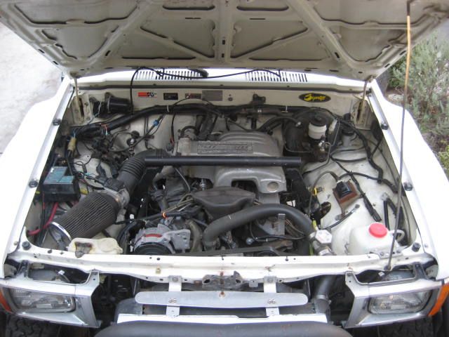
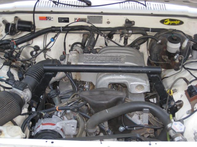
Well that's about it for the current suspension set up on the 85'. Stay tuned and I'll post some pictures of the 86' Fordota Engine compartment and the LT suspension.
For rear shocks I had some Pro-Comp ES 3000s for a 4" lifted truck. They were a tad bit long before but now with the blocks just about right. I took some measurements and found that even with the blocks one side would bottom out by 1.5" And I know the 35s would definitely rub the rear fender. Time for some bump stop shimming. I ended up using a 1.5x2 rectangular tube and a 4" base plate bolted onto the factory frame bracket. Now I am getting full spring droop and bump stop limited up travel within the range of my shock stroke.
Well that's about it for the current suspension set up on the 85'. Stay tuned and I'll post some pictures of the 86' Fordota Engine compartment and the LT suspension.
 01-06-2013, 02:14 PM
#28
Registered User
Thread Starter
Yeah, its out of a 1987 Mustang. Rated at 225 hp from the factory. Torque is around 300 lb-ft. Its like having two 22RE motors under the hood.
07-09-2013, 08:14 AM
#30
Registered User
are you happy with the skyjacker leafs up front? do they look to be settling yet? im looking to get a set on the front of mine, thats why im asking thanks. SWEET RIG'S BTW DEF JEALOUS!!
07-09-2013, 08:28 PM
#31
Registered User
Thread Starter
Yeah, the SkyJackers leaf springs in the front are decent. Much better than the rusted out ones I had. What I had was too harsh; it had add-a-leafs so it was over sprung. The spring rate on the SkyJackers are much softer and they flex better.
The latest thing I did was replaced the front 2" longer spring shackles with 1" longer. The new ones are only an inch shorter but its made the steering geometry less quirky. I still think the pinion angel of the front axle is off and so is the caster. I could go back to the stock shackles (another 1" less) and that would probably do the trick. But then I loose lift and the spring cannot expand and contact as well and won't show as much travel.
As far as settle, I have not noticed much of that happening. After I replaced the front shackle it did lower a tiny bit. The rear is really affected by loads so when the tank is empty and I don't have anything in the bed the rear sits high. But a full tank and a few items in the bed and the rear is too low. I guess overall I have it set just about right.
Last edited by BlazeN8; 07-09-2013 at 08:39 PM.
02-05-2014, 09:37 AM
#33
Registered User
Thread Starter
Its been a while since I visited this thread but I had a few updates over the past six months. The first thing is the head gasket blew out on the 1985 22RE. Not too bad of a repair. I did replace the head with a rebuild. So far so good, its running nicely but I also swapped out tires to 315/75/R16 so now when I am driving the performance with the new head is moot as stock gearing is even more off.
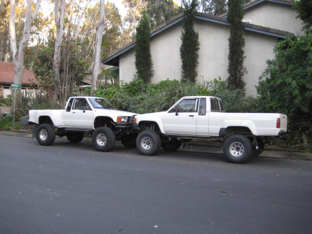
I did take a trip up the canyon and snapped a couple of photos on the RTI rock. Anyway here they are.
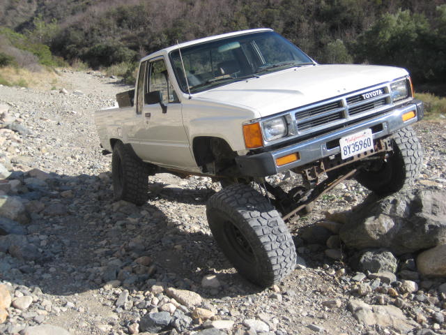
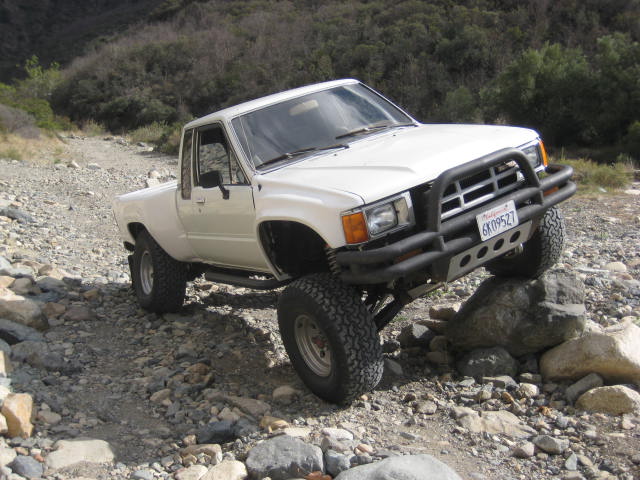
The 1985 looks more extreme and crossed up than the IFS to me. I think its a visual trick due to the Camber of the wheels? Could also be the difference in the rear suspension travel is greater on the IFS rig. Or maybe it has something to do with tire size as IFS is 33" and SA is 35" Possibly a slight difference in the camera angle. What ever the case its the same rock!
I did take a trip up the canyon and snapped a couple of photos on the RTI rock. Anyway here they are.
The 1985 looks more extreme and crossed up than the IFS to me. I think its a visual trick due to the Camber of the wheels? Could also be the difference in the rear suspension travel is greater on the IFS rig. Or maybe it has something to do with tire size as IFS is 33" and SA is 35" Possibly a slight difference in the camera angle. What ever the case its the same rock!
02-05-2014, 11:32 AM
#35
Nice pair of trucks, it's cool to see a side by side comparison of nearly identical trucks SA vs LT ifs on the same terrain!
Just curious what radiator your using in Fordota? Also is your grill moved forward to make room for the radiator? It's hard to tell in the one pic because of the Smittybuilt bumper. It looks good, just wondering because when I did my 302 swap on my 86' 4runner I had a lot of clearance issues with the core support trying to fit the radiator and electric fans in, I'm wondering if the serpentine water pump on your newer 302 is shorter than the older style v-pulley waterpump on my carbureted 302? I'm currently just running a Toyota V6 radiator and need to upgrade to something better, just trying to figure out a solution without having to cut out the rest of my core support, lol, thanks in advance- Ed.
Just curious what radiator your using in Fordota? Also is your grill moved forward to make room for the radiator? It's hard to tell in the one pic because of the Smittybuilt bumper. It looks good, just wondering because when I did my 302 swap on my 86' 4runner I had a lot of clearance issues with the core support trying to fit the radiator and electric fans in, I'm wondering if the serpentine water pump on your newer 302 is shorter than the older style v-pulley waterpump on my carbureted 302? I'm currently just running a Toyota V6 radiator and need to upgrade to something better, just trying to figure out a solution without having to cut out the rest of my core support, lol, thanks in advance- Ed.
Last edited by rustED; 02-05-2014 at 11:52 AM.
02-05-2014, 03:07 PM
#36
Registered User
Thread Starter
Look at the top picture and follow the upper radiator hose. You should be able to make out the radiator. It is located in front of the core support and behind the Smittybuilt bumper. This was a temporary location from 1998. I was going to figure out what your working on, but I got frustrated as nothing would fit unless I hacked up the core support. It worked so well I just got a new radiator with side tanks without bungs. Then had a radiator shop locate the bungs on the tanks that fit through core support with the least amount of cutting.
There are two 10" electric fans within the core support. The fans only come on at idle under slow speeds or stopped. There is plenty of room between the core support and the accessory pulley to add a super charger!
The down side is all the weight hanging off the front. Some day I would like to move the radiator to the bed. This would let me build a lighter pre-runner style bumper. Or make it look more stock with a pre-runner light bar with the original bumper and grill. I'd also like to restore the AC condenser to the factory location and stay cool in the So. Cal. desert.
02-05-2014, 03:30 PM
#37
Registered User
Thread Starter
Basically but to be more precise I should provide some more detail and updated measurements. The front has a SkyJacker lift spring that I thought was a 3" lift but it is more likely a 4" lift. And I added longer shackles. It is more accurately measuring out to be about 5" of suspension up front. In the rear I have a Downey 3" lift spring with a Deaver Mini-pack and 1" blocks. It also has longer shackles. The total lift in the rear is more accurately 5" So total lift front and rear is 5" suspension and 2" body lift. I have also done some bump stop shimming so that the 35s are not rubbing.
05-12-2014, 09:51 PM
#38
Registered User
Thread Starter
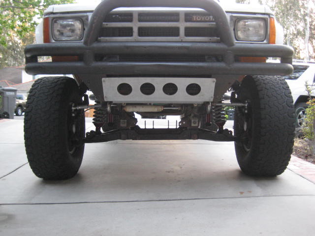
Not much new going on with the 1985 except I took off the 315/75/R16 tires and rims and put them back on my 4Runner. I replaced them with the 33s off the Fordota as I made some changes to the IFS. I put it on stilts! Yep, IFS Long Travel with a 4" Drop Bracket kit. The "Combo Kit" as I call it. The DB kit is cobbled together from a couple of brands as well as some of my own components. The drop bracket is Trail Master with a CMdiff subframe I built. The spindle spacer is Superlift. I'll get into the details a bit later but here is the photo montage.
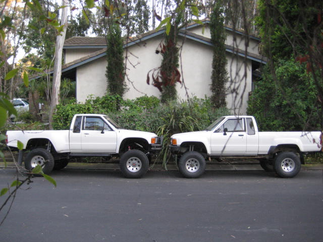
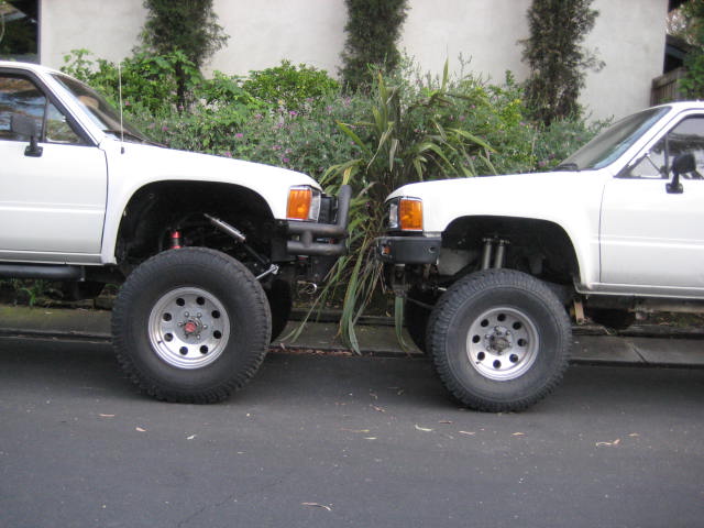
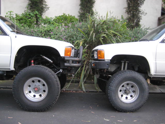
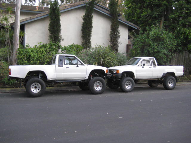
As you can see the lift in the front is a now couple of inches higher and appears to be slightly higher than the Solid Axle rig. However the visual appearance is slightly misleading as the IFS rig is now on 35s. Specifically 315/75/R16. The larger tire makes the IFS sit 1" higher purely because of tire size. Also the larger opening fiberglass fenders tricks the eye.
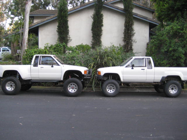
Despite the tires and visual tricks these trucks are nearly identical now in lift height. Interestingly from different camera angles lift height appearance varies.
From this angle the 1985 looks higher.
From this angle the 1986 looks higher.
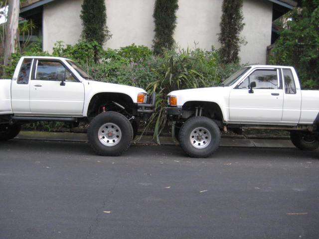
Here are some close ups of the suspension. Zooming in a bit closer.
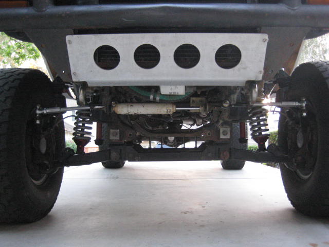
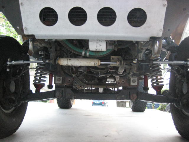
And the LH side.
The RH side.
A bit later I will go over the details. Items such as the heim joint steering, the CMdiff subframe, the shock hoop changes, and the lack of functional bump stops. As of now I have only aligned the front end in terms of tape measurement for Tow and visual check of the Camber. I drove around the block a few times and its tracking straight and feels really stable. In summary, the front of the IFS went from 3" lift to 5" lift. You would think more because or the 4" DB but the angle of the control arms are now almost flat. It doesn't feel all that much higher. Anyway, that it for tonight.
As you can see the lift in the front is a now couple of inches higher and appears to be slightly higher than the Solid Axle rig. However the visual appearance is slightly misleading as the IFS rig is now on 35s. Specifically 315/75/R16. The larger tire makes the IFS sit 1" higher purely because of tire size. Also the larger opening fiberglass fenders tricks the eye.
Despite the tires and visual tricks these trucks are nearly identical now in lift height. Interestingly from different camera angles lift height appearance varies.
From this angle the 1985 looks higher.
From this angle the 1986 looks higher.
Here are some close ups of the suspension. Zooming in a bit closer.
And the LH side.
The RH side.
A bit later I will go over the details. Items such as the heim joint steering, the CMdiff subframe, the shock hoop changes, and the lack of functional bump stops. As of now I have only aligned the front end in terms of tape measurement for Tow and visual check of the Camber. I drove around the block a few times and its tracking straight and feels really stable. In summary, the front of the IFS went from 3" lift to 5" lift. You would think more because or the 4" DB but the angle of the control arms are now almost flat. It doesn't feel all that much higher. Anyway, that it for tonight.
Last edited by BlazeN8; 05-15-2014 at 05:15 PM.
05-14-2014, 07:31 PM
#39
Registered User
Thread Starter
The Drop Bracket subframe replaces the the 11 ga. factory front cross member and 1/8" wall aftermarket rear crossmember (not shown). The new subframe improves the old crossmember configuration with better geometry and stepping up the thickness of the steel. By connecting the front to rear and side to side pieces together with a rigid frame of heavy wall construction, strength is improved and movement reduced.
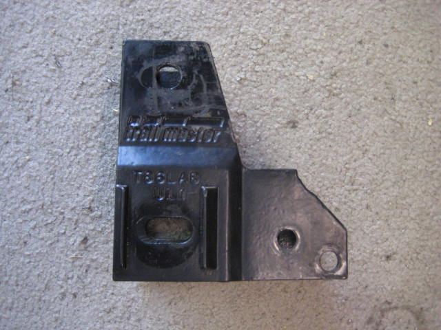
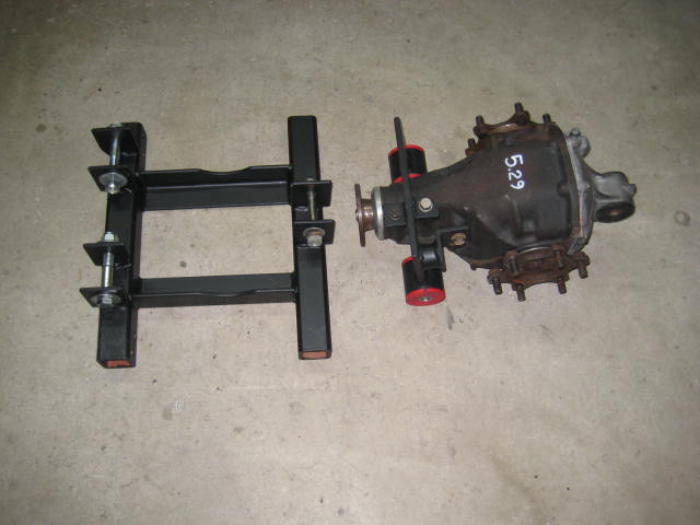
Here is the subframe with the four Trail Master drop bracket stilts attached. And below that is one of the T.M. corner pieces (typical of 4)
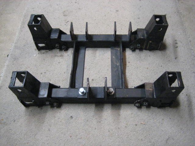
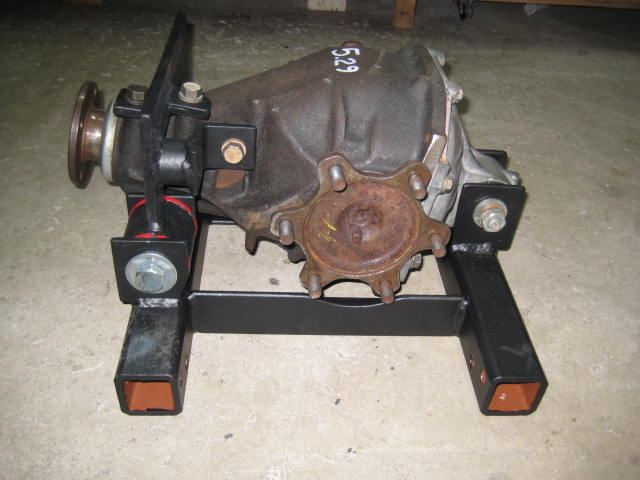
The drop bracket subframe is designed to hold the stock 7.5 Differential in a center mount configuration. To modify the 7.5 Diff for this configuration one would remove the side axle tube, grinding away 1/4" of material and then plug in a second stub axle flange. Then the modified 3rd member unit is bolted to some brackets and connected to the subframe.
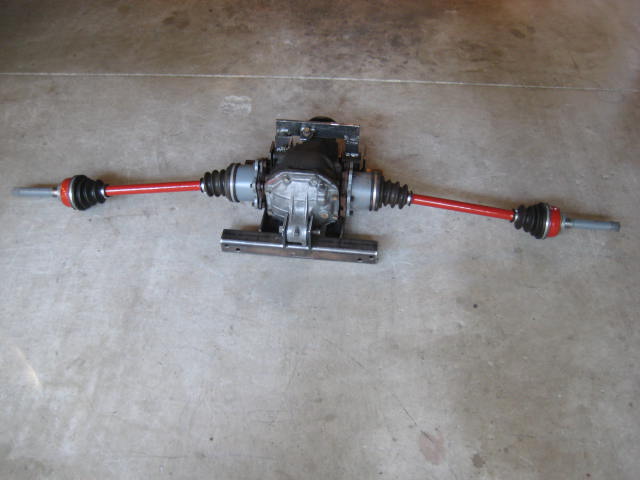
The CV axle assembly is the stock Truck and 4Runner with longer center bars. This can be accomplished with either a custom machined axle or buy cutting and sleeving what you got. The CMdiff configuration is able to handle up to 16" of wheel travel. However designing the other components to cycle 16" is another story. As for now, this is truck is undergoing a budget build as a sample to showcase the Blazeland Long Arms in combination with a 4" Drop Bracket Kit. It is designed for 13" of wheel travel.
Here is the subframe with the four Trail Master drop bracket stilts attached. And below that is one of the T.M. corner pieces (typical of 4)
The drop bracket subframe is designed to hold the stock 7.5 Differential in a center mount configuration. To modify the 7.5 Diff for this configuration one would remove the side axle tube, grinding away 1/4" of material and then plug in a second stub axle flange. Then the modified 3rd member unit is bolted to some brackets and connected to the subframe.
The CV axle assembly is the stock Truck and 4Runner with longer center bars. This can be accomplished with either a custom machined axle or buy cutting and sleeving what you got. The CMdiff configuration is able to handle up to 16" of wheel travel. However designing the other components to cycle 16" is another story. As for now, this is truck is undergoing a budget build as a sample to showcase the Blazeland Long Arms in combination with a 4" Drop Bracket Kit. It is designed for 13" of wheel travel.
Last edited by BlazeN8; 05-14-2014 at 07:35 PM.
05-15-2014, 05:03 PM
#40
Registered User
Thread Starter
The CMdiff set up seems like overkill since I am targeting for 13" of wheel travel, but I am also looking at future growth as well. Eventually I will be installing the Mega Travel like I have on my 4Runner. Besides that I already have the spare modified diff and a set of CVs.
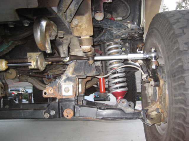
The next issue that needs to be addressed is the steering. Using the factory Tie Rod Ends and longer Tie Rod Adjusting Sleeves is fine for 12� but much more and the outer TRE binds. Time to step up to Heim Joint steering!
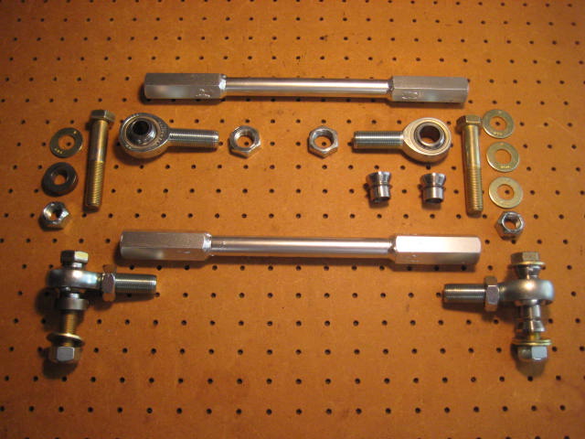
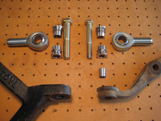
Converting to Heim Joint steering is quite expensive. Quality heims, misalignment spacers, jam nuts, high grade hardware, and custom machined adjusting sleeves add up. Machining adjusting sleeves with all the needed clearances and specific length is the biggest cost and requires the most effort. I developed some fittings to reduce machining and to allow DIY lengths.
The fittings consist of RH or LH threaded ends on one side and the other side a bore to fit a round bar you cut to length.
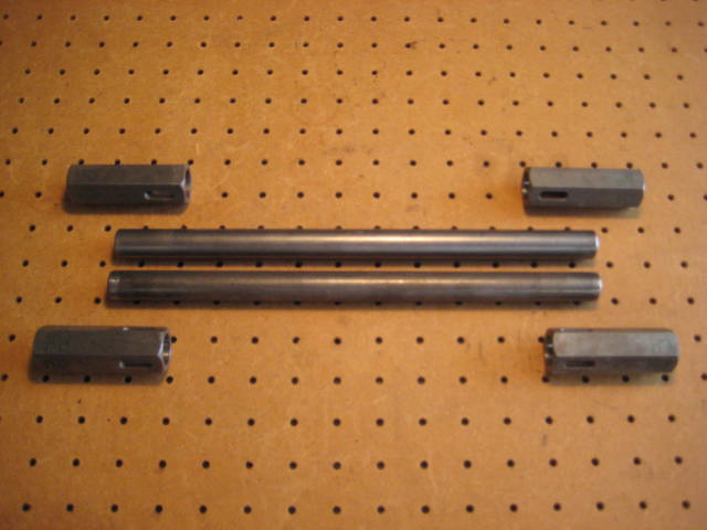
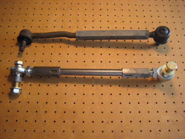
In my application I had a known Tie Rod assembly to use as a guide to set the length. From there it was just a matter of cutting the bar to length.
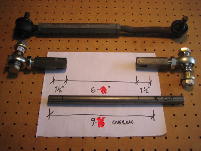
Here is the assembly slip fit to length.
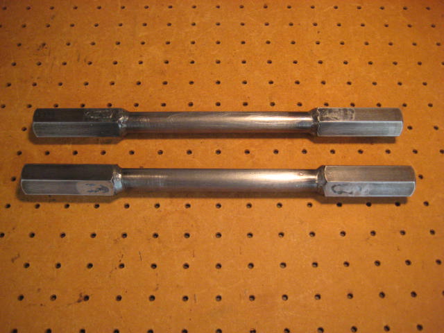
And then it�s a matter of some perimeter and plug welds. Here are the sleeves all welded and ready for paint.
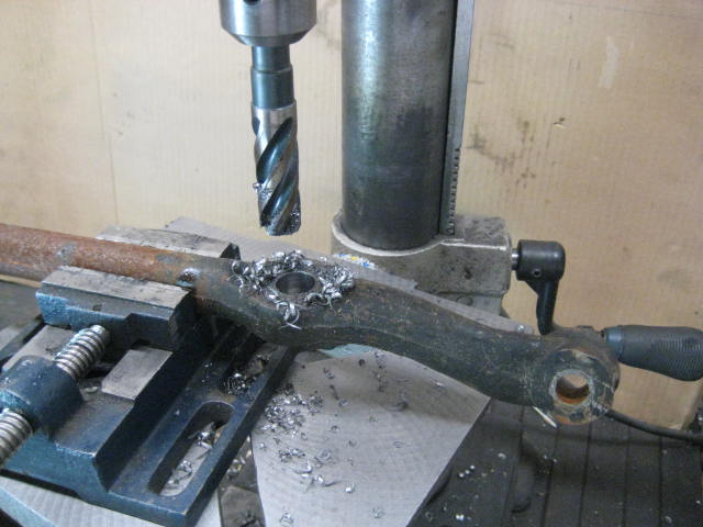
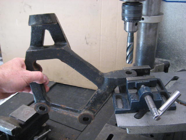
The next step is to drill out the tapered hole in the Center Link. It needs to be drilled out to 5/8" I suggest using a four flute Hogger bit. Make sure you only drill out the holes that accept the inner tie rod ends.
Then you need to repeat the drilling process at the steering arm on the spindle spacer.
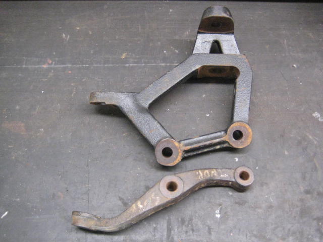
Here is a reference photo of the spindle spacer w/ steering arm (top) and the factory steering arm (bottom)
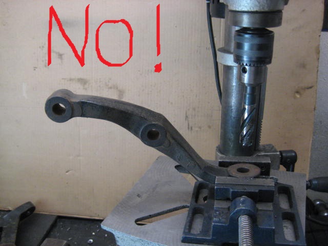
As a related side note, if you were using the factory Steering Arms you wouldn't want to drill out the taper.
The aftermarket spindle spacer / steering arms alter the steering link geometry. The spindle distance increases by 4" while the steering arm increases by 5". This raises the outer link by an inch meaning the angle of the heim is reduced.
With the factory steering arm the heim joint needs 35 degrees at full droop while the spindle spacer steering arm only needs 30 degrees.
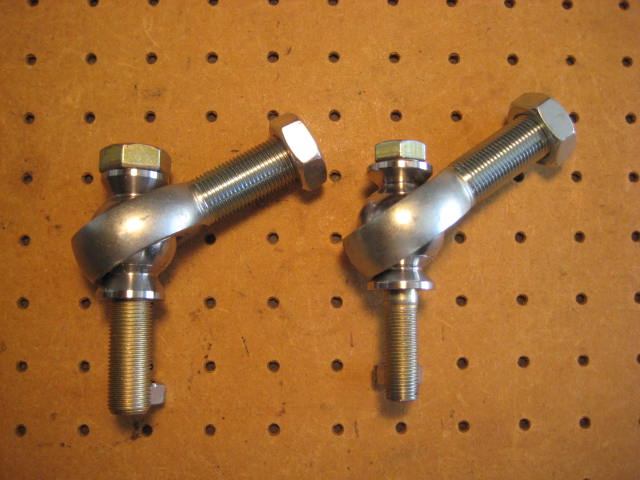
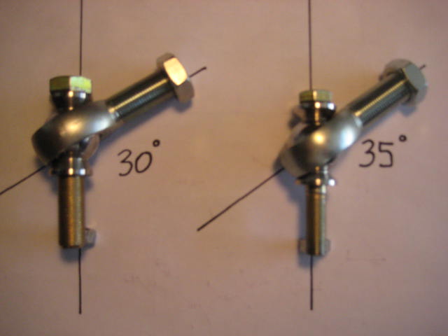
To get 35 degrees means the bolt in the misalignment spacer has to be 1/2" The smaller bolt allows a misalignment spacer reduction which allows a greater angle and it fits into the tapered hole with a tapered adapter. This is nice as it means no need to drill out the hole in the steering arm.
But the 1/2" bolt is not strong enough. Look how much smaller the bolt is.
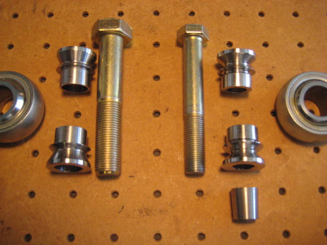
If you are going to use the 1/2" bolt you should weld some gussets to the steering arm and make it a double shear connection.
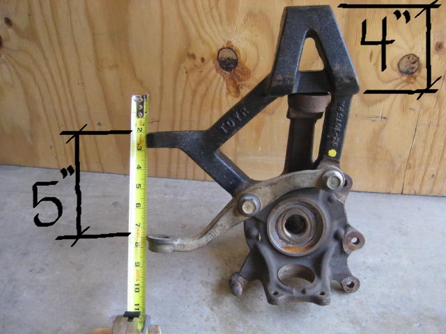
With the factory steering arm the distance from the spindle bolt to the tapered hole is a cantilever of approximately 4" With the spindle spacer the distance from the "Y� intersection is less than an inch and there is more material. The spindle spacer configuration is a much stronger geometry as is a 5/8" bolt so a double shear connection isn't as critical.
If you study the geometry of the spindle spacer you can see it adds strength in other areas as well. It bolts to (3) areas of the spindle spreading the loads. The factory spindle upright is a single member. The addition of the spindle spacer creates three spindle uprights on the lower portion and two on the upper.
The next issue that needs to be addressed is the steering. Using the factory Tie Rod Ends and longer Tie Rod Adjusting Sleeves is fine for 12� but much more and the outer TRE binds. Time to step up to Heim Joint steering!
Converting to Heim Joint steering is quite expensive. Quality heims, misalignment spacers, jam nuts, high grade hardware, and custom machined adjusting sleeves add up. Machining adjusting sleeves with all the needed clearances and specific length is the biggest cost and requires the most effort. I developed some fittings to reduce machining and to allow DIY lengths.
The fittings consist of RH or LH threaded ends on one side and the other side a bore to fit a round bar you cut to length.
In my application I had a known Tie Rod assembly to use as a guide to set the length. From there it was just a matter of cutting the bar to length.
Here is the assembly slip fit to length.
And then it�s a matter of some perimeter and plug welds. Here are the sleeves all welded and ready for paint.
The next step is to drill out the tapered hole in the Center Link. It needs to be drilled out to 5/8" I suggest using a four flute Hogger bit. Make sure you only drill out the holes that accept the inner tie rod ends.
Then you need to repeat the drilling process at the steering arm on the spindle spacer.
Here is a reference photo of the spindle spacer w/ steering arm (top) and the factory steering arm (bottom)
As a related side note, if you were using the factory Steering Arms you wouldn't want to drill out the taper.
The aftermarket spindle spacer / steering arms alter the steering link geometry. The spindle distance increases by 4" while the steering arm increases by 5". This raises the outer link by an inch meaning the angle of the heim is reduced.
With the factory steering arm the heim joint needs 35 degrees at full droop while the spindle spacer steering arm only needs 30 degrees.
To get 35 degrees means the bolt in the misalignment spacer has to be 1/2" The smaller bolt allows a misalignment spacer reduction which allows a greater angle and it fits into the tapered hole with a tapered adapter. This is nice as it means no need to drill out the hole in the steering arm.
But the 1/2" bolt is not strong enough. Look how much smaller the bolt is.
If you are going to use the 1/2" bolt you should weld some gussets to the steering arm and make it a double shear connection.
With the factory steering arm the distance from the spindle bolt to the tapered hole is a cantilever of approximately 4" With the spindle spacer the distance from the "Y� intersection is less than an inch and there is more material. The spindle spacer configuration is a much stronger geometry as is a 5/8" bolt so a double shear connection isn't as critical.
If you study the geometry of the spindle spacer you can see it adds strength in other areas as well. It bolts to (3) areas of the spindle spreading the loads. The factory spindle upright is a single member. The addition of the spindle spacer creates three spindle uprights on the lower portion and two on the upper.


