OM617 Tachometer using SR5 Tach
 03-24-2013, 01:27 PM
#1
Registered User
Thread Starter
OM617 Tachometer using SR5 Tach
I have finally gotten my SR5 gauge cluster's tachometer to work with my OM617. I bought the DSL-1 flywheel tachometer signal sender unit. If anyone is interested, I have an extra 4 cyl bellhousing that I machined for the flywheel tooth sensor that I will sell if you don't want to go through that hassle. I will be posting a full tutorial with pictures once this snow melts... If you were debating ordering the Dakota Digital unit, though, go ahead and order it. It works great!
 03-27-2013, 05:39 AM
#2
Registered User

Join Date: Apr 2010
Posts: 35
Likes: 0
Received 0 Likes
on
0 Posts
I used the Dakota with an alternator input and that worked fine too. I probably could calibrate a little better, but it is pretty close right now. The flywheel or crank sensor is definitely the most accurate way to go, but more work.
03-29-2013, 10:21 PM
#3
Registered User
Thread Starter
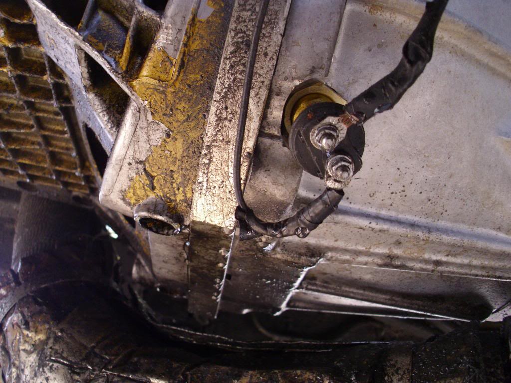
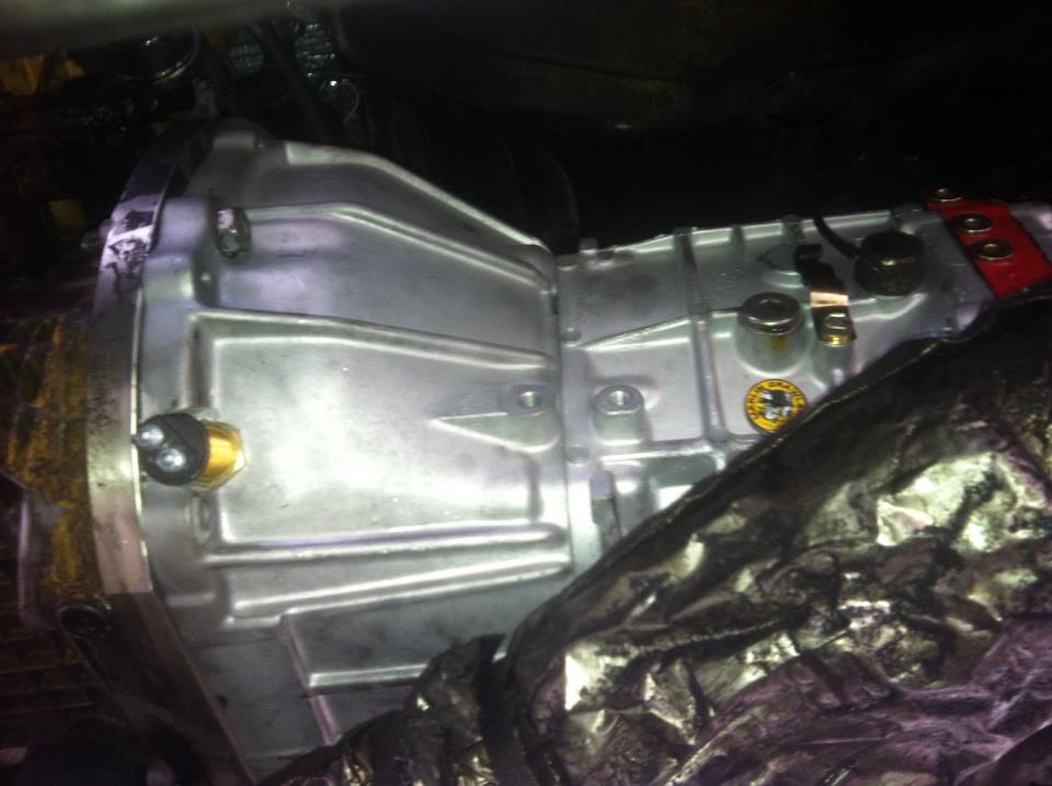
To make an SR5 gauge cluster's tachometer from a 22R 4x4 manual Toyota Pickup 1986, you can use the Dakota Digital flywheel tooth sensor. The first step is to mount the tooth sensor in the bellhousing, centering the sensor on the flywheel teeth, keeping it perpendicular to the flywheel, and spacing it 1/8 inch away. You will run two wires to the circuit board.
Next you will tap a wire into an ignition-on > hot wire. Find a good ground and use it for both the sensor and the circuit board. The last wire will go back into the tachometer. Take the dash out (5 screws).
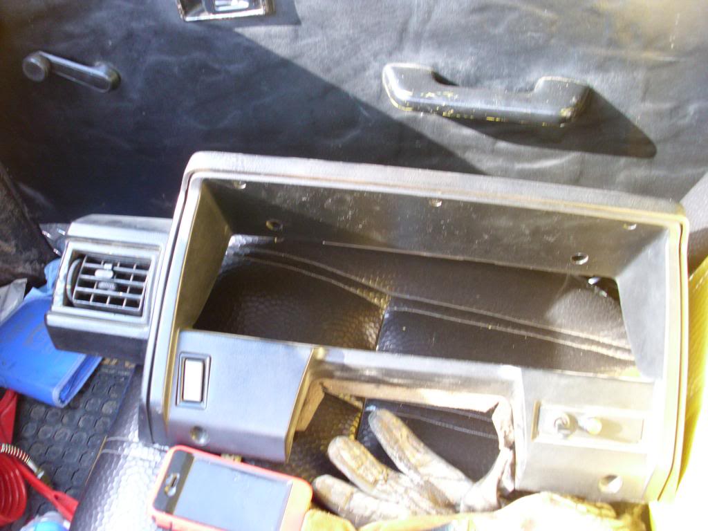
Then pull the gauge cluster out (4 more screws).
Then strip a good amount of wire from your circuit board and fold it over to make a hook and shove it into the quick connector in the location shown so that it feeds the "Tach" input.
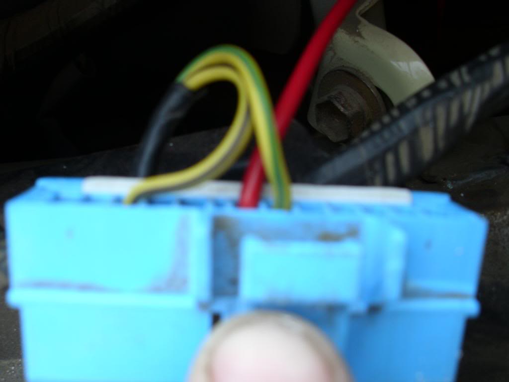
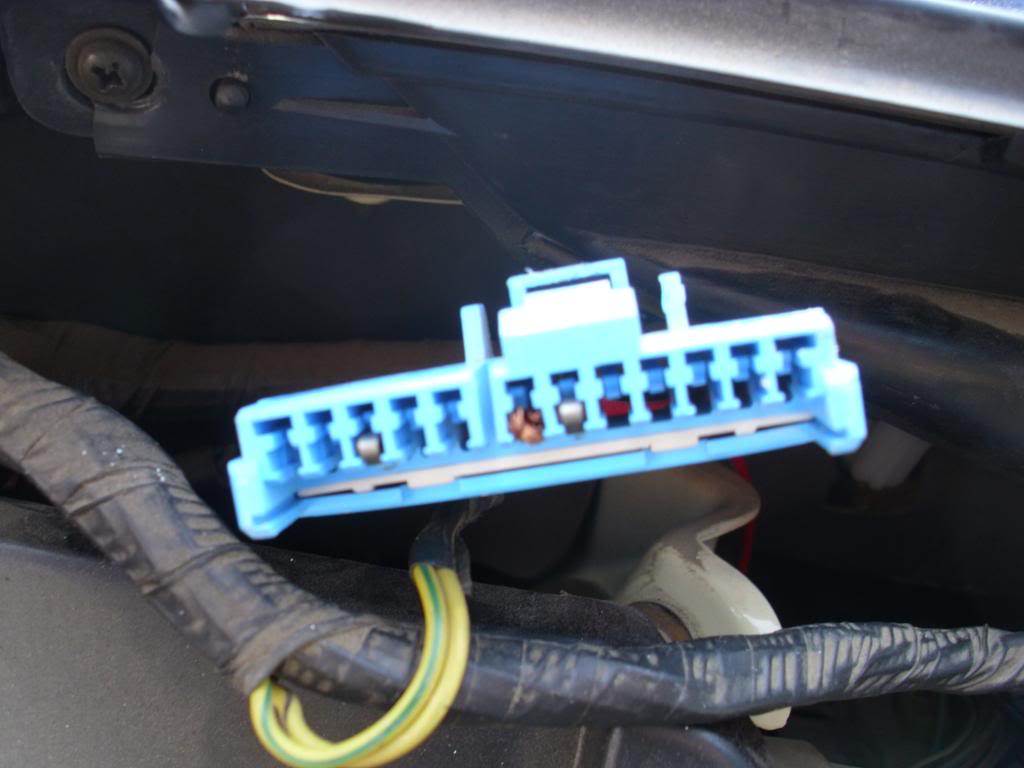
Try to strip off the least amount of wire possible to insert into the circuit board. I stripped too much. I used 14 gauge which seemed to be a perfect fit. Solid 1 strand wire would probably work best.
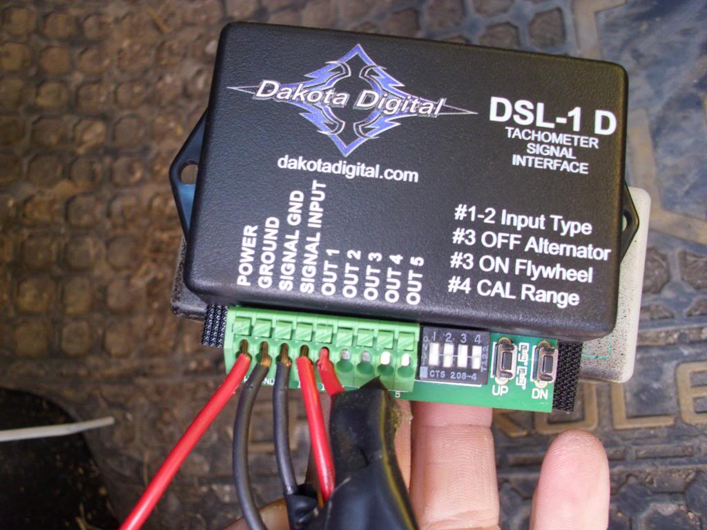
Now for the calibrating and the reason I created this thread. I soldered in a 22.5 Kilo-ohm resistor between the tach signal and tach ground wires to allow the tach to read the negative signal. Use the V-8 high voltage output for the tach signal. Set the switches as follows:
Switch 1 OFF
Switch 2 OFF
Switch 3 ON
Switch 4 ON
Hold the DN button while turning the ignition on, then let go. The red light will flash. Press up until the light flashes 10 times. Shut the key off.
Hold the UP button while turning the ignition on, then let go. The greed light will flash. Press up until the light flashes 14 times. Shut the key off.
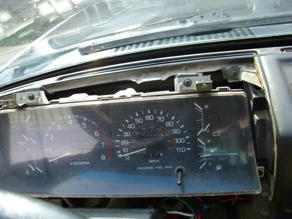
This will give you a low ratio of .7 something-ish. My tach is spot on now. It took me a about 12 tries to get it perfect. With SWITCH 4 ON, you will get the low ratio of your UP DN combination.
And as a result, you get this:

Next you will tap a wire into an ignition-on > hot wire. Find a good ground and use it for both the sensor and the circuit board. The last wire will go back into the tachometer. Take the dash out (5 screws).
Then pull the gauge cluster out (4 more screws).
Then strip a good amount of wire from your circuit board and fold it over to make a hook and shove it into the quick connector in the location shown so that it feeds the "Tach" input.
Try to strip off the least amount of wire possible to insert into the circuit board. I stripped too much. I used 14 gauge which seemed to be a perfect fit. Solid 1 strand wire would probably work best.
Now for the calibrating and the reason I created this thread. I soldered in a 22.5 Kilo-ohm resistor between the tach signal and tach ground wires to allow the tach to read the negative signal. Use the V-8 high voltage output for the tach signal. Set the switches as follows:
Switch 1 OFF
Switch 2 OFF
Switch 3 ON
Switch 4 ON
Hold the DN button while turning the ignition on, then let go. The red light will flash. Press up until the light flashes 10 times. Shut the key off.
Hold the UP button while turning the ignition on, then let go. The greed light will flash. Press up until the light flashes 14 times. Shut the key off.
This will give you a low ratio of .7 something-ish. My tach is spot on now. It took me a about 12 tries to get it perfect. With SWITCH 4 ON, you will get the low ratio of your UP DN combination.
And as a result, you get this:
Last edited by pyrojoe22; 09-18-2013 at 05:59 AM.
09-18-2013, 06:04 AM
#6
Registered User
Thread Starter
It doesn't matter. It's a common ground. If I zoomed my picture out, you'd see that the ground wire feeding into the "Ground" terminal and the wire feeding into the "Signal Ground" terminal are the same wire split into a "Y" about 2 inches back.

Thread
Thread Starter
Forum
Replies
Last Post
Tcsdef
General Electrical & Lighting Related Topics
1
09-07-2015 11:17 PM


