OM617 into 1987 4Runner SR5

 12-08-2015, 02:31 AM
#62
Registered User
Thread Starter
Thanks toastyjosh!! 
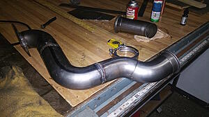
Got the downpipe done & installed, here is a pic of it before the welding was finished and it went in.
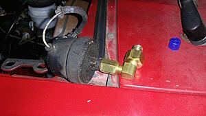
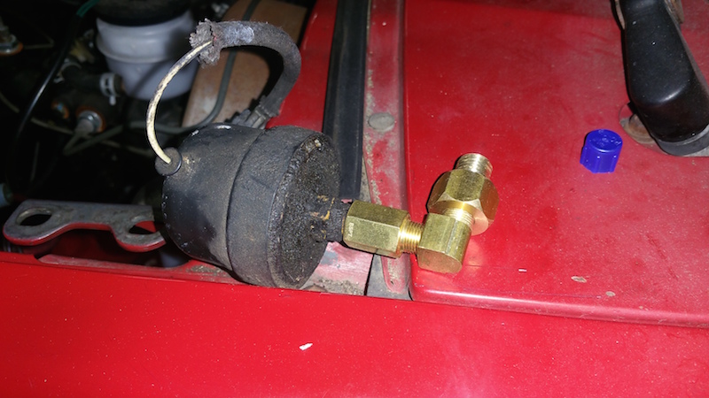
Here is a photo of the Toyota oil pressure sender with the two adapters applied to it, ready to be tightened into the 617 (I have a placeholder bolt in there now). This is a 1/8 BSPT (Toy pressure sender) to 1/8 NPT adapter from mcmaster, followed by a 1/8 NPT to 12mm 1.5 elbow adapter from mercedesdiesel4x4. i wasn't able to source a 1/8 BSPT to 12mm elbow, so two adapters were required.
I am getting really far along with the wiring, still have to wire the fans using the circuit opening relay. I was also thinking because the COR has a logic level coil, I can use the already onboard arduino to monitor the water temp and enable the fan at a given temperature, in addition to the kill switch in the cab. This saves me the trouble of finding a separate water temp sensor switch. I'll be getting to that sometime later, after the car is drivable.
My friggin hood latch line's cable housing stop broke at the plastic part, which renders it pretty much useless in its current state. Gonna have to research an easy way to fix it, or maybe have to pick one up at the scrap yard!
Either way I am hoping to go on the first test drive tomorrow!
Got the downpipe done & installed, here is a pic of it before the welding was finished and it went in.

Here is a photo of the Toyota oil pressure sender with the two adapters applied to it, ready to be tightened into the 617 (I have a placeholder bolt in there now). This is a 1/8 BSPT (Toy pressure sender) to 1/8 NPT adapter from mcmaster, followed by a 1/8 NPT to 12mm 1.5 elbow adapter from mercedesdiesel4x4. i wasn't able to source a 1/8 BSPT to 12mm elbow, so two adapters were required.
I am getting really far along with the wiring, still have to wire the fans using the circuit opening relay. I was also thinking because the COR has a logic level coil, I can use the already onboard arduino to monitor the water temp and enable the fan at a given temperature, in addition to the kill switch in the cab. This saves me the trouble of finding a separate water temp sensor switch. I'll be getting to that sometime later, after the car is drivable.
My friggin hood latch line's cable housing stop broke at the plastic part, which renders it pretty much useless in its current state. Gonna have to research an easy way to fix it, or maybe have to pick one up at the scrap yard!
Either way I am hoping to go on the first test drive tomorrow!
12-08-2015, 12:56 PM
#63
Registered User
Thread Starter
Test drive complete! No major issues to report
This thing is a dog off of the line, but once the turbo gets going it holds a nice steady speed with ease on the highway.
I think I need to adjust alda for better off the line response. More to come, still have some wire tidying to do and have to hook up all of the gauges
This thing is a dog off of the line, but once the turbo gets going it holds a nice steady speed with ease on the highway.
I think I need to adjust alda for better off the line response. More to come, still have some wire tidying to do and have to hook up all of the gauges
12-08-2015, 01:27 PM
#64
Registered User
A cheap and easy efan controller is found on most early 2000 Volvo.
On my build thread I outlined what I did.
https://www.yotatech.com/forums/f199...7/index90.html
Hope this helps
On my build thread I outlined what I did.
https://www.yotatech.com/forums/f199...7/index90.html
Hope this helps
12-08-2015, 04:39 PM
#65
Registered User
Thread Starter
Thanks RBX! That looks like a great option too.
Well here it is for now
The second time I took it out (after adjusting alda a little bit) I snapped some video:
https://vimeo.com/148300513
Well here it is for now

The second time I took it out (after adjusting alda a little bit) I snapped some video:
https://vimeo.com/148300513
12-08-2015, 10:04 PM
#67
Registered User
Thread Starter
Thanks!! 
Just took it for a drive with some friends. It seems so very slow at all times, can't be right. When I went to go adjust the alda today, the tappet screw on top of it was backed out so far that I saw my flathead start to bend trying to free it (a cheap flathead but still). I was reading on some other forums that backing it out too far can cause damage to it internally, and the previous owner had backed it so far out that it was TIGHT. Not a good sign, but perhaps a good place to look.
Another possibility is that the banjo bolt there is clogged
Right now it feels a lot slower than the 22re... so slow off the line that it almost feels a tad dangerous.
12-09-2015, 12:39 AM
#68
Registered User
Thread Starter
Removed alda, test drove, and bingo
Car is now way faster than 22re and has just as much off the line pickup. I was a little worried there for a sec.
I am going to try shimming the alda, seems like the thing to do. For anyone wondering, alda is a positive pressure actuated pushrod that limits fuel by pulling back the IP's rack position (throttle) at idle- as I understand it. A lot of people are under the misconception that it adds fuel... Actually if you adjust the alda tappet "out" it just means it should limit less. Take it off and no limiting. By using a shim, you lessen the limiting farther than just unscrewing the tappet even all the way out, but you don't take away its beneficial properties. I think the most beneficial one is overboost protection.
12-09-2015, 11:41 PM
#70
Registered User
Thread Starter
Thanks! I've already put about 40 or 50 miles on it, but I still definitely have a few big things left to do along with all the other tweaks to get it where I want it.
Right now it's running straight out of the downpipe... Well this is obviously temporary as it is way too loud and stinky. Gonna add a straight through muffler somewhere along the pipe when I make the rest of the exhaust. I have a box half full of 3" mandrel bends begging to be assembled!
I still need to do tach (all other gauges working), and I gotta look into why my rear power window stopped working. I guess I unplugged something at some point. Hope I didn't clip it! As far as tach, I hooked it up like in my wiring diagram. But I've been doing research and it looks like the MB tach amp puts out 3ms long pulses at 6V, while the sr5 cluster wants a 12v square wave. Not sure if I can get these two to work together, but one can hope and try!
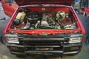
As the motor mounts have settled, the engine dropped a little more than expected. Now the motor is a little too close to the front differential. I am thinking about making some plate shims for sliding under the motor mounts- trying to raise it up a 1/4" if I can. Also, I absolutely need to do some slight massage on the oil pan. The steering linkage still drags the pan when almost to a full lock. Ugh so close! So sick of taking the pan off! I might see if there is a way I can massage it with a wedge while it's on the car (being really careful)
Overall impression so far: I keep thinking that maybe the 22re was faster, but I think it's more likely that I have just been desensitized to acceleration from only riding my motorcycle for the past ~8 months. Either way it would be nice if it was a little faster. My buddy who is a MB diesel fan (same guy who helped me with a lot of the heavy stuff at the beginning) wants to come back to town in coming months to tune the IP and make some small performance adjustments. Looking forward, until then I gotta get everything clean and functioning well!
Right now it's running straight out of the downpipe... Well this is obviously temporary as it is way too loud and stinky. Gonna add a straight through muffler somewhere along the pipe when I make the rest of the exhaust. I have a box half full of 3" mandrel bends begging to be assembled!
I still need to do tach (all other gauges working), and I gotta look into why my rear power window stopped working. I guess I unplugged something at some point. Hope I didn't clip it! As far as tach, I hooked it up like in my wiring diagram. But I've been doing research and it looks like the MB tach amp puts out 3ms long pulses at 6V, while the sr5 cluster wants a 12v square wave. Not sure if I can get these two to work together, but one can hope and try!
As the motor mounts have settled, the engine dropped a little more than expected. Now the motor is a little too close to the front differential. I am thinking about making some plate shims for sliding under the motor mounts- trying to raise it up a 1/4" if I can. Also, I absolutely need to do some slight massage on the oil pan. The steering linkage still drags the pan when almost to a full lock. Ugh so close! So sick of taking the pan off! I might see if there is a way I can massage it with a wedge while it's on the car (being really careful)
Overall impression so far: I keep thinking that maybe the 22re was faster, but I think it's more likely that I have just been desensitized to acceleration from only riding my motorcycle for the past ~8 months. Either way it would be nice if it was a little faster. My buddy who is a MB diesel fan (same guy who helped me with a lot of the heavy stuff at the beginning) wants to come back to town in coming months to tune the IP and make some small performance adjustments. Looking forward, until then I gotta get everything clean and functioning well!
12-10-2015, 07:44 AM
#71
Registered User
iTrader: (1)
Join Date: Dec 2010
Location: new mexico
Posts: 393
Likes: 0
Received 0 Likes
on
0 Posts
http://www.idparts.com/bosio-injecto...14-p-3085.html
http://dieselgiant.com/mercedesinjec...zlereplace.htm
This should help a little along with tuning the pump.
http://dieselgiant.com/mercedesinjec...zlereplace.htm
This should help a little along with tuning the pump.
12-11-2015, 07:00 PM
#72
Registered User
Thread Starter
Thanks toasty!
I shimmed the motor mounts with a few 3/16" plates, and adjusted the oil pan where it was contacting the steering linkage.
For anyone looking to do this build, make sure you measure your steering linkage in all positions (full lock left, right, and in the middle) before you modify the oil pan. At full lock, the bar moves forward. I didn't think of this, so it lead to a bit of headache down the line
I still haven't figured out what's wrong with my back window, why it won't go up. More time in the FSM for me.
Otherwise running great, just can't wait to get the exhaust done & sounding right (sounds a little nuts straight out of the downpipe)
Last edited by jennygirl; 12-11-2015 at 07:02 PM.
12-12-2015, 05:08 AM
#73
Registered User
http://www.4crawler.com/4x4/CheapTri...arWindow.shtml
For rear window issues. I added two relays to bypass the rear window computer. Unlike a regular front window the rear control is sent thru a box that detects if the wiper is up, gate is down or top is on. If any of those sensors aren't reading correctly the window will not work. I deleted my wiper sensor(never used the rear wiper) and deleted the hardtop sensor so I can lock the rear gate will driving cuz I always forget to lock it when I shut it with the top off.
For rear window issues. I added two relays to bypass the rear window computer. Unlike a regular front window the rear control is sent thru a box that detects if the wiper is up, gate is down or top is on. If any of those sensors aren't reading correctly the window will not work. I deleted my wiper sensor(never used the rear wiper) and deleted the hardtop sensor so I can lock the rear gate will driving cuz I always forget to lock it when I shut it with the top off.
12-12-2015, 08:52 AM
#74
Registered User
Thread Starter
Whew! I thought I was going to have to do something similar to that, or at the very least chase the wiring from the power window relay. I had already tested most of the sensor switches as of last night, then this morning did one more search (probably about the 15th by now) as I gathered tools to tear into it. I ran across this:
http://board.marlincrawler.com/index.php?topic=72604.0
Similar situation, harness cut from the engine bay and suddenly no dice on the rear window. I tried this fix and it worked!! Blah! I've spent quite a few hours in the FSM trying to track this down. Well, should I ever have a future problem with a sensor switch or relay, I have a much greater understanding now
I guess the power window switches must be grounded through the engine bay or somewhere around the ECU, because that is where I clipped most wires/connectors. That ground musta gone missing, and I'm guessing the switches weren't seeing a circuit because of it (not seeing ground like they should). I tested by adding that one wire to ground, and everything works as expected!
Time to happily move on to the next thing
12-12-2015, 11:40 AM
#75
Super Moderator
Staff
iTrader: (1)
Join Date: Aug 2008
Location: Anderson Missouri
Posts: 11,788
Likes: 0
Received 21 Likes
on
19 Posts
I see you got it fixed but here is how I bypass all safetys
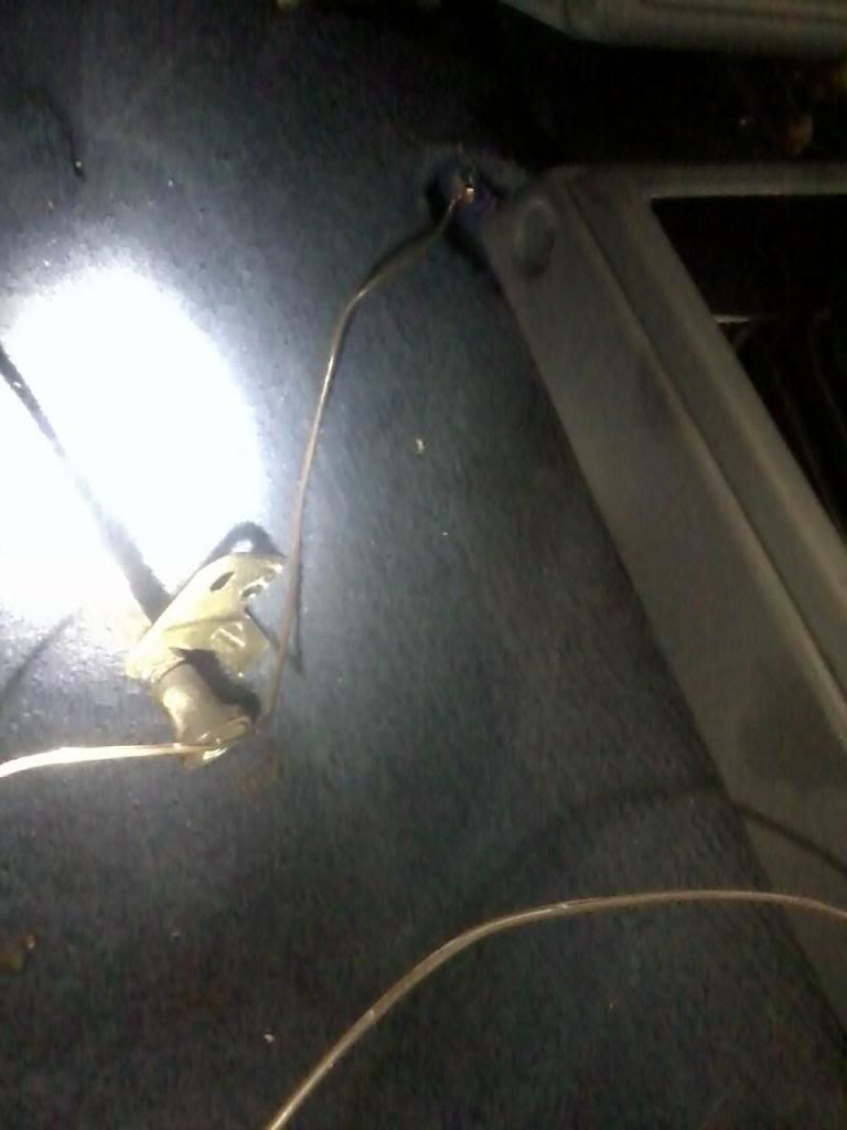
Running a ground wire from this wire on the plug, the blue wire to the place on the pic below elminates a lot of problems.
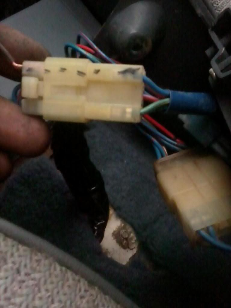
Ground to center consloe mounting tab.
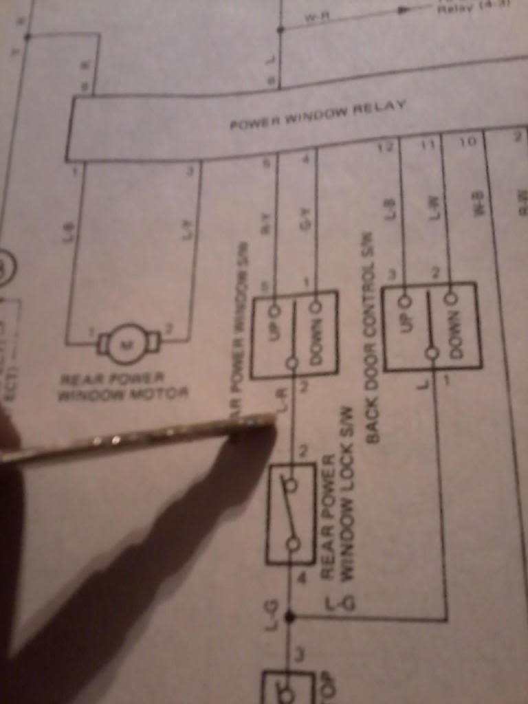
The ground wire bypasses the following safety switches. Cover Top and Door Lock Detections switch. Your window will roll up with top off. This is on Page 12-23 of the Haynes Manual where the key is to the botom of the page.
Haynes "L" for Blue, "R" for Red. Key is pointing to wire.
Running a ground wire from this wire on the plug, the blue wire to the place on the pic below elminates a lot of problems.
Ground to center consloe mounting tab.
The ground wire bypasses the following safety switches. Cover Top and Door Lock Detections switch. Your window will roll up with top off. This is on Page 12-23 of the Haynes Manual where the key is to the botom of the page.
Haynes "L" for Blue, "R" for Red. Key is pointing to wire.
12-12-2015, 06:11 PM
#76
Registered User
Thread Starter
Sweeeet!! Good to know I also have full control now 
Thanks!
I relocated the parking brake this morning by drilling 3 holes down and slightly to the left of where the mount was initially. It is about 6" down and 1" to the left, very close to the steering column. This gave me adequate routing around the oil filter housing, and I also hammered the firewall to get it flat with the engine side cable housing bracket..
Inside, I welded a 1" extension piece to the bracket that holds the parking brake lever. Good to have a parking brake again.
12-13-2015, 08:30 AM
#77
Registered User
Thread Starter
I've been doing a bit more research on tachometer stuff. It is definitely going to require a bit of R&D. I have quite a bit of experience with dc electrical, but I am no electrical engineer.
What I have found out is that the Tachometer Amplifier unit that came out of the mercedes hooks up to a magnetic sensor at the crank near the front left of the motor with a grey wire. The tach amp signal line supposedly spits out a 3 millisecond pulse of 5-6V for every revolution and returns to 0V in it's off state. The toyota dash, though, is looking for a 12V square wave (originally sent from the igniter) which increases frequency depending on engine speed (4 pulses per revolution).
The easiest option I can think of is to use a microcontroller like an arduino to read and interpret the incoming 5V pulse from the tach amp, and then drive the tach gauge using an NPN transistor to amplify the arduino's 5V tone output (which generates a 5V squarewave at a given frequency) to 12V
I should theoretically be able to route the tach amp signal directly into one of the arduino's digital input pins and write a function to interpret the timing as a variable. Then, I would scale that variable X4 and output the frequency as a square wave tone, have it switch a transistor which brings it to 12V, and hook that directly into the tach gauge.
More to come on this. I am also open to any ideas from anyone who has a bit more know-how in this field!
Last edited by jennygirl; 12-13-2015 at 08:35 AM.
12-13-2015, 02:48 PM
#78
Registered User

Join Date: Dec 2015
Posts: 1
Likes: 0
Received 0 Likes
on
0 Posts
tach interface
Nice build! Have you checked out Dakota Digital's tach interface that uses a flywheel gear tooth sensor and sends a signal to your stock tach. (link below)
http://www.dakotadigital.com/index.c...rod/prd129.htm
http://www.dakotadigital.com/index.c...rod/prd129.htm
Last edited by tractors0130; 12-13-2015 at 03:13 PM.
12-13-2015, 07:59 PM
#79
Registered User
Join Date: Jan 2010
Location: Vancouver, Wa
Posts: 150
Likes: 0
Received 0 Likes
on
0 Posts
Sweet build!
Yepper Pepper, I was going to suggest the Dakota Digital option that Tractors mentioned.
I ended up using a mini-tach whilst working out my options, and it seems that the stock Mercedes tach amp is notoriously unreliable. (I know I went through two while running the mercedes tach in the cab for a few months and trying to resolve the signals.)
If you really want to build it yourself, you could just use the pulse from the mercedes pick-up (before the amp), and set your sensitivity threshold on the arduino, and translate the signal to the 12v square freq.
Don't fret on the power until you get it dialed in, and having the alda intake fitting clean and adjusted properly will make all of the difference on the low-end. I also saw a big improvement with rebuilding my injectors with Monark nozzles. Greazzer on STD is a known, trusted rebuilder.
What are you running for boost? Here is a I shot vid of wastgate removal:
Oh, and adjusting my fuel pressure spring was also a big help. It was nearly 7mm off! (Since then I have used a higher rated spring with good results.)
http://www.peachparts.com/shopforum/...ss-spring.html
There is a lot to be gained from adjusting the IP, but be sure to use a pyrometer!
And of course with an OM617 adjust your valves every 10k or so...
12-15-2015, 12:13 PM
#80
Great build you have going here!! I desperately want to put a Diesel in Mine.
I did not pay attention to your screen name and was taken back when I saw your picture. Its always nice to see women who are knowledgeable and capable with Automobiles, and a Bonus when they are Pretty!!
I did not pay attention to your screen name and was taken back when I saw your picture. Its always nice to see women who are knowledgeable and capable with Automobiles, and a Bonus when they are Pretty!!


